【Time6】时钟约束
Primary Clocks 主时钟
主时钟定义了整个时序分析的起点也可以说是参考点(0时刻)
vivado会忽略主时钟的上游时序,只关注主时钟的下游。
create_clock [-name clock_name] \
    -period period_value \
    [-waveform edge_list] \
    [-add] \
    [source_objects]
管脚进入的时钟
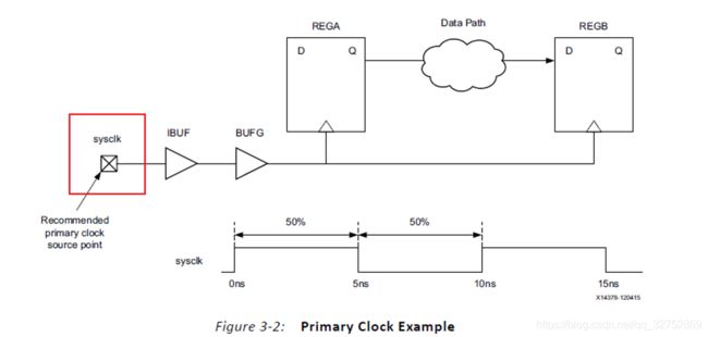
推荐把主时钟定义为顶层管脚上,未经过IBUF,这样可以把IBUF的延时也考虑进时序分析。
等占空比、无相移
• Its period is 10 ns.
• Its duty cycle is 50%.
• Its phase is not shifted.
create_clock -period 10 [get_ports sysclk]
非等占空比、有相移
• Its period is 10 ns.
• Its duty cycle is 25%.
• It is phase shifted by 90 degrees.
create_clock -name devclk -period 10 -waveform {2.5 5} [get_ports ClkIn]
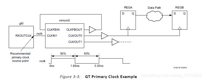
GTP恢复时钟
create_clock -name rxclk -period 3.33 [get_pins gt0/RXOUTCLK]
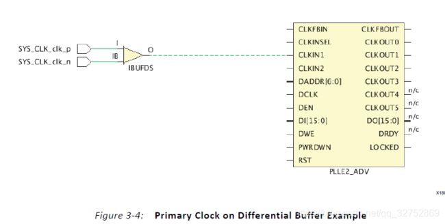
差分时钟
只要约束P极。
create_clock -name sysclk -period 3.33 [get_ports SYS_CLK_clk_p]
Virtual Clocks
虚拟时钟是不绑定物理网络节点的时钟,没有时钟源。
虚拟时钟通常用于input and output delay 约束
当两个时钟之间不是整数倍,但是有跨时钟,就会出现不符合实际的时序路径要求
create_clock -name clk_virt -period 10
Generated Clocks 生成时钟
生成时钟约束:是用来描述生成时钟与主时钟的关系;
不是描述生成时钟的周期和波形,而是描述如何从主时钟得到生成时钟。
生成时钟一般来自时钟修改模块(PLL/MMCM/BUFR)或者用户逻辑代码(分频器)。
主时钟master clock:primary clock 或者 另一个generated clock
source pin:主时钟的源pin(为什么有这个?因为source pin到master clock之间有可能有延时)
为了计算生成的时钟的延迟,工具跟踪生成的时钟的源引脚和主时钟的源引脚之间的顺序和组合路径。在某些情况下,可能需要只跟踪组合路径来计算生成的时钟延迟。您可以使用-combinational命令行选项来实现这一点。
分频,倍频,分频倍频组合、相移或波形反转、占空比改变和以上改变的组合.
create_generated_clock [-name clock_name] \
    -source master_pin \
    [-master_clock clock] \
    [-edge edge_list] \
    [-edge_shift shift_list] \
    [-divide_by factor] \
    [-multiply_by factor] \
    [-duty_cycle percent] \
    [-combinational]
    [-invert] \
    [-add] \
    source_objects
the master clock for this clock assignment could not be derived. ID:332087
有-master_clock,但是-source的时钟找不到;
无-master_clock,并且-source的时钟找不到;
无-master_clock,并且-source的时钟不唯一;
例子
等占空比、无相移
方法一:
create_clock -name clkin -period 10 [get_ports clkin]
# Option 1: master clock source is the primary clock source point
create_generated_clock -name clkdiv2 -source [get_ports clkin] -divide_by 2 \
[get_pins REGA/Q]
# Option 2: master clock source is the REGA clock pin
create_generated_clock -name clkdiv2 -source [get_pins REGA/C] -divide_by 2 \
[get_pins REGA/Q]方法二:
# waveform specified with -edges instead of -divide_by
create_generated_clock -name clkdiv2 -source [get_pins REGA/C] -edges {1 3 5} \
[get_pins REGA/Q]生成时钟的上升沿开始的一个周期内的主时钟的上升和下降沿位置{1 3 5 },从上升沿开始,时钟沿初始不是0,而是1.也可以省略下降沿,只要用单纯的上升沿能描述清楚。
非等占空比、有相移
-edge_shift:参考主时钟对应的沿的移位值,
例如:
参考主时钟的edge1上升沿,应该右移2.5ns
参考主时钟的edge2下降沿,应该不移动0ns
参考主时钟的edge3上升沿,应该右移动2.5ns
create_clock -name clkin -period 10 [get_ports clkin]
create_generated_clock -name clkshift -source [get_pins mmcm0/CLKIN] -edges {1 2 3} \
-edge_shift {2.5 0 2.5} [get_pins mmcm0/CLKOUT]
# First rising edge: 0ns + 2.5ns = 2.5ns
# Falling edge: 5ns + 0ns = 5ns
# Second rising edge: 10ns + 2.5ns = 12.5ns
分数分频
create_generated_clock -name clk43 -source [get_pins mmcm0/CLKIN] -multiply_by 4 \
-divide_by 3 [get_pins mmcm0/CLKOUT]
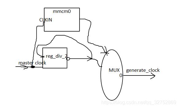
选组合路径
我们希望在多路复用器输出上创建一个生成的时钟,该时钟反映从主时钟到多路复用器的组合路径的延迟。
create_generated_clock -name clkout -source [get_pins mmcm0/CLKIN] -combinational
[get_pins MUX/O]
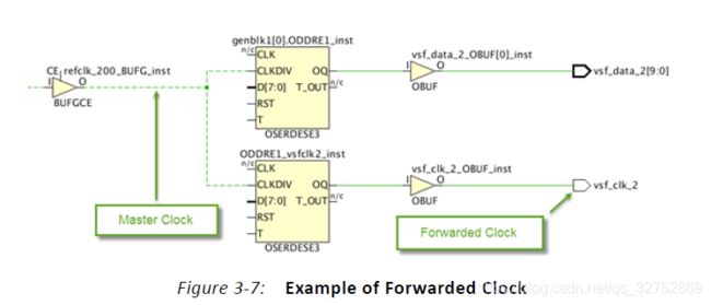
ODDR驱动的前向时钟
create_generated_clock -name ck_vsf_clk_2 \
-source [get_pins ODDRE1_vsfclk2_inst/CLKDIV] -divide_by 1 [get_ports vsf_clk_2]
参考手册Using Constraints UG903
从TimeQuest角度看create_generated_clock
从TimeQuest角度看create_generated_clock - 重归混沌 - 博客园
create_generated_clock的使用问题
Xilinx Customer Community
