【HDLBits】Module(verilog模块的例化)
通过一些HDLBits上面的题目来练习一些例化。
1.Module
By now, you’re familiar with a module, which is a circuit that interacts with its outside through input and output ports. Larger, more complex circuits are built by composing bigger modules out of smaller modules and other pieces (such as assign statements and always blocks) connected together. This forms a hierarchy, as modules can contain instances of other modules.
The figure below shows a very simple circuit with a sub-module. In this exercise, create one instance of module mod_a, then connect the module’s three pins (in1, in2, and out) to your top-level module’s three ports (wires a, b, and out). The module mod_a is provided for you — you must instantiate it.
When connecting modules, only the ports on the module are important. You do not need to know the code inside the module. The code for module mod_a looks like this:
module mod_a ( input in1, input in2, output out );
// Module body
endmodule
The hierarchy of modules is created by instantiating one module inside another, as long as all of the modules used belong to the same project (so the compiler knows where to find the module). The code for one module is not written inside another module’s body (Code for different modules are not nested).
You may connect signals to the module by port name or port position. For extra practice, try both methods.

两种例化的方法:
一种是通过位置,一种是通过名称
By position
The syntax to connect wires to ports by position should be familiar, as it uses a C-like syntax. When instantiating a module, ports are connected left to right according to the module’s declaration. For example:
mod_a instance1 ( wa, wb, wc );
This instantiates a module of type mod_a and gives it an instance name of “instance1”, then connects signal wa (outside the new module) to the first port (in1) of the new module, wb to the second port (in2), and wc to the third port (out). One drawback of this syntax is that if the module’s port list changes, all instantiations of the module will also need to be found and changed to match the new module.
按位置将电线连接到端口的语法应该很熟悉,因为它使用类似 C 的语法。实例化模块时,端口根据模块的声明从左到右连接。例如:
mod_a instance1 ( wa, wb, wc );
这将实例化一个类型的模块mod_a并为其提供实例名称“instance1”,然后将信号wa(在新模块之外)连接到新模块的第一个端口 ( in1)、wb第二个端口 ( in2) 和wc第三个端口 ( out)。这种语法的一个缺点是,如果模块的端口列表发生更改,则还需要找到并更改模块的所有实例以匹配新模块。
注意是从左到右或者是从右往左,要按顺序,这种方法不太flexible
By name
Connecting signals to a module’s ports by name allows wires to remain correctly connected even if the port list changes. This syntax is more verbose, however.
mod_a instance2 (
 .out(wc),
 .in1(wa),
 .in2(wb)
 );
The above line instantiates a module of type mod_a named “instance2”, then connects signal wa (outside the module) to the port named in1, wb to the port named in2, and wc to the port named out. Notice how the ordering of ports is irrelevant here because the connection will be made to the correct name, regardless of its position in the sub-module’s port list. Also notice the period immediately preceding the port name in this syntax.
module top_module(
input a,
input b,
output out
);
mod_a mod_a0
(
.in1(a),
.in2(b),
.out(out)
);
endmodule
2.Module pos
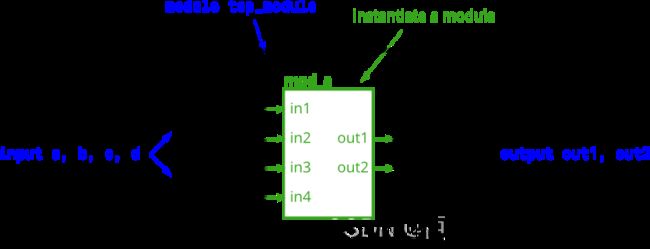
This problem is similar to the previous one (module). You are given a module named mod_a that has 2 outputs and 4 inputs, in that order. You must connect the 6 ports by position to your top-level module’s ports out1, out2, a, b, c, and d, in that order.
You are given the following module:
module mod_a ( output, output, input, input, input, input );

module top_module (
    input a,
    input b,
    input c,
    input d,
    output out1,
    output out2
);

    mod_a mod_a0
(
out1,
out2,
a,
b,
c,
d
);
endmodule
3.Module name
This problem is similar to module. You are given a module named mod_a that has 2 outputs and 4 inputs, in some order. You must connect the 6 ports by name to your top-level module’s ports:
Port in mod_a Port in top_module
output out1 out1
output out2 out2
input in1 a
input in2 b
input in3 c
input in4 d
You are given the following module:
module top_module (
    input a,
    input b,
    input c,
    input d,
    output out1,
    output out2
);
    mod_a mod_a0
(
.in1(a),
.in2(b),
.in3(c),
.in4(d),
.out1(out1),
.out2(out2)
);

endmodule
4. Module shift
You are given a module my_dff with two inputs and one output (that implements a D flip-flop). Instantiate three of them, then chain them together to make a shift register of length 3. The clk port needs to be connected to all instances.
The module provided to you is: module my_dff ( input clk, input d, output q );
Note that to make the internal connections, you will need to declare some wires. Be careful about naming your wires and module instances: the names must be unique.
例化长度为3的移位寄存器

module top_module3(
input clk,
input d,
output q
);
wire w1;
wire w2;


my_dff d0(
.clk(clk),
.d(d),
.q(w1)
);
my_dff d1(
.clk(clk),
.d(w1),
.q(w2)
);
my_dff d2(
.clk(clk),
.d(w2),
.q(q)
);
endmodule
5.Module fadd
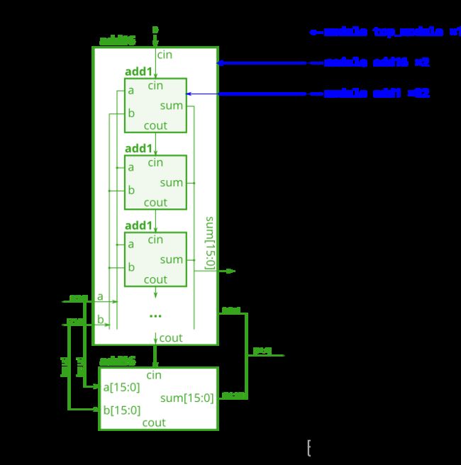
In this exercise, you will create a circuit with two levels of hierarchy. Your top_module will instantiate two copies of add16 (provided), each of which will instantiate 16 copies of add1 (which you must write). Thus, you must write two modules: top_module and add1.
Like module_add, you are given a module add16 that performs a 16-bit addition. You must instantiate two of them to create a 32-bit adder. One add16 module computes the lower 16 bits of the addition result, while the second add16 module computes the upper 16 bits of the result. Your 32-bit adder does not need to handle carry-in (assume 0) or carry-out (ignored).
Connect the add16 modules together as shown in the diagram below. The provided module add16 has the following declaration:
module add16 ( input[15:0] a, input[15:0] b, input cin, output[15:0] sum, output cout );
Within each add16, 16 full adders (module add1, not provided) are instantiated to actually perform the addition. You must write the full adder module that has the following declaration:
module add1 ( input a, input b, input cin, output sum, output cout );
Recall that a full adder computes the sum and carry-out of a+b+cin.
In summary, there are three modules in this design:
top_module — Your top-level module that contains two of…
add16, provided — A 16-bit adder module that is composed of 16 of…
add1 — A 1-bit full adder module.
If your submission is missing a module add1, you will get an error message that says Error (12006): Node instance “user_fadd[0].a1” instantiates undefined entity “add1”.
实在不想看英语了,于是使用了谷歌翻译。编写两个模块top_module,add1。例化两个16位加法器,以创建32位加法器。第一个add16模块计算加法结果的低16位,第二个加法模块计算加法结果的高16位。此处的32位加法器不需要处理进位。这题要自己写一个16位加法器。
module top_module (
    input [31:0] a,
    input [31:0] b,
    output [31:0] sum
);//
wire cout1,cout2;
//两个16位加法器的例化
add16 add16_lower(
.a(a[15:0]),
.b(b[15:0]),
.cin(0),
.sum(sum[15:0]),
.cout(cout1)
);
add16 add16_higher(
.a(a[31:16]),
.b(b[31:16]),
.cin(cout1),
.sum(sum[31:16]),
.cout(cout2)
);
endmodule


module add1 ( input a, input b, input cin,   output sum, output cout );
assign cout = (a && b) || (a && cin) || (b && cin);
assign sum = (a && ~b && ~cin) || (~a && ~b && cin) || (~a && b && ~cin)|| (a && b && cin);
// Full adder module here

endmodule
6. Module cseladd
One drawback of the ripple carry adder (See previous exercise) is that the delay for an adder to compute the carry out (from the carry-in, in the worst case) is fairly slow, and the second-stage adder cannot begin computing its carry-out until the first-stage adder has finished. This makes the adder slow. One improvement is a carry-select adder, shown below. The first-stage adder is the same as before, but we duplicate the second-stage adder, one assuming carry-in=0 and one assuming carry-in=1, then using a fast 2-to-1 multiplexer to select which result happened to be correct.
In this exercise, you are provided with the same module add16 as the previous exercise, which adds two 16-bit numbers with carry-in and produces a carry-out and 16-bit sum. You must instantiate three of these to build the carry-select adder, using your own 16-bit 2-to-1 multiplexer.
Connect the modules together as shown in the diagram below. The provided module add16 has the following declaration:
module add16 ( input[15:0] a, input[15:0] b, input cin, output[15:0] sum, output cout );

百度翻译:ripple进位加法器的一个缺点(参见前面的练习)是,加法器计算进位的延迟(在最坏的情况下,从进位开始)相当慢,并且在第一级加法器完成之前,第二级加法器无法开始计算其进位。这会使加法器变慢。一个改进是进位选择加法器,如下所示。第一级加法器与之前相同,但我们复制了第二级加法器,一个假设进位=0,一个假设进位=1,然后使用快速2-1多路复用器选择正确的结果。
在本练习中,您将获得与上一练习相同的模块add16,==该模块将两个16位数字与进位相加,并生成进位和16位和。==必须实例化其中三个,才能使用自己的16位2对1多路复用器构建进位选择加法器。
如下图所示,将模块连接在一起。提供的模块add16具有以下声明:
模块add16(输入[15:0]a,输入[15:0]b,输入cin,输出[15:0]和,输出cout);
module top_module(
    input [31:0] a,
    input [31:0] b,
    output [31:0] sum
);
    wire sel;
    wire [15:0] output1,output2;
    add16 add16_instance1(.a(a[15:0]), .b(b[15:0]), .cin(0), .sum(sum[15:0]), .cout(sel));
    add16 add16_instance2(.a(a[31:16]), .b(b[31:16]), .cin(0), .sum(output1));
    add16 add16_instance3(.a(a[31:16]), .b(b[31:16]), .cin(1), .sum(output2));

    always@* begin
        case(sel)
            0: sum[31:16] = output1;
            1: sum[31:16] = output2;
        endcase
    end
endmodule