基于FPGA的图像实时缩放
使用插值算法实现图像缩放是数字图像处理算法中经常遇到的问题。我们经常会将某种尺寸的图像转换为其他尺寸的图像,如放大或者缩小图像。由于在缩放的过程中会遇到浮点数,如何在FPGA中正确的处理浮点数运算是在FPGA中实现图像缩放的关键。
一、插值算法原理
在图像的缩放处理过程中,经常会用到插值算法,常见的插值算法包括最邻近插值,双线性插值,双三次线性插值,兰索斯插值等方法。其中,双线性插值由于折中的插值效果和实现复杂度,运用较为广泛。本文中仅介绍最临近插值,重点讨论如何在FPGA平台上使用双线性插值实现图像的缩放。
1.1 最临近插值---------最临近插值介绍
讲理论不如举例子来的快,所以为了更好更快的理解最临近插值,我们通过举个简单的例子来解释最临近插值是个什么神奇的东西。假如有一个3*3矩阵(一幅图像其实就是矩阵),如下,我们把这个图像叫做原图(source image):
66 28 128
25 88 200
36 68 120
在矩阵中,坐标(x,y)是这样确定的,矩阵的左上角的顶点为原点,从左到右为x轴,从上到下为y轴,如下所示:
 图1 图像中坐标确定方式
假设我们想把这个3*3的原图扩大成4*4(我们把这个4*4的图像叫做目的图像destination image)我们该如何做呢?首先当然是先把4*4的矩阵画出来,如下所示:
? ? ? ?
? ? ? ?
? ? ? ?
? ? ? ?
矩阵画出来后,接下来就要像未知数里填充像素点了。要填入的值如何计算呢,通过如下公式进行计算:![]()
![]()
首先我们先来填充目的图像 (0,0),套用上述公式可得到对应原图像的坐标点,srcX =0,srcY= 0;找到原图像中对应的坐标点的像素值,将该像素填充到目的图像中,如下
66 ? ? ?
? ? ? ?
? ? ? ?
接下来填充目的图像(1,0),仍然套用公式,srcX = 3/4,srcY = 0,结果发现得到的结果居然有小数,由于计算机中的像素点已经是最小单位,像素的坐标都是整数,没有小数。这是只需要按照四舍五入的思想将小数坐标转换为整数坐标即可.所以(3/4,0) ≈ (1,0),把原图像中(1,0)点的像素值填入目的图像(1,0)坐标处,得到如下结果:
66 28 ? ?
? ? ? ?
? ? ? ?
接下来重复上述过程,就可得到放大后的目的图像,如下:
66 28 128 128
25 88 200 200
36 68 120 120
36 68 120 120
这种放大图像的方法叫做最临近插值算法,这是一种最基本最简单的图像缩放算法,该方法缩放后的图像会出现失真现象。
1.2 双线性插值算法
双线性插值算法是一种比较好的缩放算法,它充分利用源图中虚拟点四周的四个像素点来共同决定目标图形中的一个像素值,因此缩放效果要比最临近插值算法好的多。
双线性插值算法的描述如下:
对于目的图像中的某点坐标,通过乘以缩放倍数(srcwidth/dstwidth、srcheight/dstheight)得到一个浮点坐标(i+u,j+v)(其中i,j均为浮点坐标的整数部分;u,v为浮点坐标的小数部分),则这个浮点坐标(i+u,j+v)处的像素值f(i+u,j+v)可以由原图像中的坐标点(i,j)、(i+1,j)、(i,j+1)、(i+1,j+1)所对应的四个像素值来共同决定,即![]()
如1.1计算的目的像素坐标(1,0)对应源图像的坐标为(3/4,0),即 i = 0,u = 0.75;j = 0,v = 0;即目的图像(1,0)处的像素值由源图像中(0,0)、(1,0)、(0,1)(1,1)四个坐标点对应的像素值来确定,代入上述公式即可计算出(3/4,0)处的像素值。
看了上述内容应该对最临近插值算法和双线性插值算法有一定的了解,其基本原理应该已经掌握。
在网上刷博客发现有好多大佬讲解了双线性插值算法的优化(双线性插值算法总结),发现优化以后缩放效果更好一些,优化的具体细节就不再讲解,具体优化过程就是使用
![]()
![]()
来代替如下公式:
![]()
![]()
写到这里双线性插值算法的基本原理及优化方式已经基本讲述完毕,那么,如何使用FPGA来实现双线性插值呢?接下来我们进行分析如何使用FPGA来实现双线性插值。
二、双线性插值的FPGA实现遇到的问题及解决方案
通过以上分析,我们会发现使用FPGA实现双线性插值有以下难点:
- 如何处理算法中出现的小数;
- 如何同时求出相邻的四个点的坐标以及系数;
- 如何使用这四个坐标同时输出相邻的四个像素值;
接下来我们依次解决上述问题
2.1 如何处理算法中出现的小数
FPGA处理浮点数一般都是将浮点数转化为定点数进行处理,我们在求srcX、srcY也按照此思想。由于FPGA中没法进行小数表示,因此我们将srcX、srcY放大一定倍数变成整数,这个整数的高n位表示坐标点的整数部分(i或j),低m位表示小数部分(u或者v)。如我们要将30*30的图像放大成64*64即srcwidth = srcheight = 30,dstwidth = dstheight =64(接下来工程实现也按照此例子来实现)。
![]()
![]()
首先将以上两个公式放大成不含小数部分,由上可知,需要放大128倍,放大后公式变为如下形式:
![]()
![]()
我们定义srcX[15:0]位宽为16位。由于放大了128倍,所以srcX[6:0]、srcY[6:0]的低7位表示小数部分,即u = srcX[6:0],v=srcY[6:0];
其余高位部分表示整数部分,即i = srcX[15:7],j = srcY[15:7]。这样就可以解决算法中出现的小数问题。
2.2如何同时求出相邻的四个点的坐标以及系数
由1.1可知,我们可以求出第一个坐标点(i,j) = (srcX[15:7],srcY[15:7]),那么如何求出相邻其它三个点的坐标呢?接下来需要求出其余三点(i+1,j)、(i,j+1)、(i+1,j+1)的坐标,
(i+1,j) = (srcX[15:7] + 'd1,srcY[15:7]);
(i,j+1) = (srcX[15:7] ,srcY[15:7] * srcwidth);
(i+1,j+1) = (srcX[15:7] + 'd1 ,srcY[15:7] * srcwidth);
通过以上方式便可以很容易的求出四个点的坐标。接下来就要考虑如何使用这四个坐标同时读取四个对应的像素值。
同时我们定义四个位宽为8位的系数变量coefficient1[7:0]、coefficient2[7:0]、coefficient3[7:0]、coefficient4[7:0],通过
coefficient1[7:0] = ‘d128 - coefficient2;(由于系数放大了128倍,所以是128-系数2,对应1-u)
coefficient2[7:0] = {1'b0,u} = {1'b0,srcX[6:0]};
coefficient3[7:0] = ‘d128 - coefficient4;(由于系数放大了128倍,所以是128-系数4,对应1-v)
coefficient4[7:0] = {1'b0,v} = {1'b0,srcY[6:0]};
为什么定义的系数变量为8位而不是7位,这是因为系数变量的最大值为’d128,8位位宽才能表示‘d128。
接下来使用上述求出的四个坐标求出对应的坐标的像素值,再套用公式
![]()
即可求出目的图像对应位置放大后的像素值。
通过以上分析,可以将公式![]() 变形为如下形式,求出对应点的像素值后直接使用以下公式即可:
变形为如下形式,求出对应点的像素值后直接使用以下公式即可:

求得该像素值之后还需要将该像素值除以128*128才是所得的实际结果。
2.3 如何使用这四个坐标同时输出相邻的四个像素值
通过2.2分析可以同时求出四个像素点的坐标,但是如何通过这四个坐标同时求出对应的像素值呢?由于待缩放的数据是先缓存进RAM的,如果待缩放的图像数据仅仅缓存在一个RAM里,是不可能通过四个像素点的坐标同时访问这个RAM,即不可能同时求出对应的四个像素点的值。所以,可以通过牺牲面积换取速度的方式,即将RAM复制4次,每个RAM都缓存整个待缩放的图像数据,这样四个像素点的坐标就可以通过访问不同的RAM来同时访问对应的四个像素值了。虽然牺牲了FPGA内部的存储资源,但是提升了双线性插值算法的速度。
三 、双线性插值的FPGA实现
通过第二节内容的分析可知,使用FPGA实现双线性插值主要包含以下三个模块:生成目的图像对应原图像坐标和系数模块、待处理图像缓存模块、双线性插值运算单元模块。其数据流向图如下图所示:
 图2 FPGA实现双线性插值数据流向图
图2中虚框部分是图像裁剪模块,这里不讨论图像裁剪功能的实现,仅仅讨论图像缩放功能的实现。
整个实现的过程描述如下:
- 上位机将待缩放的图像数据送进待处理图像缓存模块,该模块将待处理的数据复制四份
- 待1中数据缓存完毕,开始生成目的图像对应原图像坐标和系数;
- 将生成的坐标送给待处理图像缓存模块进行数据的访问,将读取的数据送给双线性插值运算单元;
- 将生成的系数送给双线性插值运算单元,与相应的像素值进行数学运算,实现双线性插值功能。
实现双线性插值功能的代码如下所示:
顶层模块:
module top(input clk,
			  output [7:0]doutb,
			  output de_o,
			  output v_sync,
			  output h_sync
    );
parameter [7:0]src_width = 'd30;
wire [7:0]coordinate_x;
wire [7:0]coordinate_y;
wire start;
wire en_b;
//
wire [7:0]coefficient1;
wire [7:0]coefficient2;
wire [7:0]coefficient3;
wire [7:0]coefficient4;
wire [7:0]doutbx;
wire [7:0]doutbx1;
wire [7:0]doutby;
wire [7:0]doutby1;
// Instantiate the module
sourceimage_virtualcoordinate coordinate (
    .clk(clk),
    .src_width(src_width),
    .start(start),
    .coordinate_x(coordinate_x),
    .coordinate_y(coordinate_y),
    .coefficient1(coefficient1),
    .coefficient2(coefficient2),
    .coefficient3(coefficient3),
    .coefficient4(coefficient4),
	 .en(en_b)
    );
//
wire [7:0]dina;
wire valid_zsc;
// Instantiate the module
self_generate self_generate (
    .clk(clk),
    .data_o(dina),
    .valid_zsc(valid_zsc)
    );
// Instantiate the module
mem_control mem_control (
    .clk_wr(clk),
    .clk_rd(clk),
    .coordinate_x(coordinate_x), /
    .coordinate_y(coordinate_y),
    .din_a(dina), /
    .en_a(valid_zsc), ///
    .src_width(src_width), //
    .en_b(en_b), ///
    .doutbx(doutbx),
    .doutbx1(doutbx1),
    .doutby(doutby),
    .doutby1(doutby1),
    .start(start)
    );
///
wire [7:0] data_o;
wire en_o;
// Instantiate the module
arithmetic_unit arithmetic_unit (
    .clk(clk),
    .coefficient1(coefficient1),
    .coefficient2(coefficient2),
    .coefficient3(coefficient3),
    .coefficient4(coefficient4),
    .en_b(en_b),
    .doutbx(doutbx),
    .doutbx1(doutbx1),
    .doutby(doutby),
    .doutby1(doutby1),
    .data_o(data_o),
	 .en_o(en_o)
    );

wire de;
wire start_en;
// Instantiate the module
mem_64multi_64 mem_64multi_64 (
    .clk(clk),
    .dina(data_o),
    .ena(en_o),
    .enb(enb),
	 .start_en(start_en),
    .doutb(doutb)
    );
// Instantiate the module
vesa_out vesa_out (
    .clk(clk),
    .start_en(start_en),
    .v_sync(v_sync),
    .h_sync(h_sync),
    .de(enb),
    .de_o(de_o)
    );
endmodule
生成对应的坐标和系数模块:
//该模块是用来计算源图像的虚拟坐标,由于源图像和目的图像都是正方形,所以只考虑一个缩放倍数即可
//
module sourceimage_virtualcoordinate(input clk,
												 input [7:0]src_width,/src_width = src_height
												 input [5:0]dest_width,/dest_width = dest_height = 'd64
												 input start,///数据缓存满了以后才可以进行计算
												 output [7:0]coordinate_x,
												 output [7:0]coordinate_y,
												 output [7:0]coefficient1,
												 output [7:0]coefficient2,
												 output [7:0]coefficient3,
												 output [7:0]coefficient4,
												 output reg en = 'd0

    );
/高电平有效rst
reg [1:0]cnt = 'd0;
always @(posedge clk)
	if(cnt == 'd3)
		cnt <= 'd3;
	else
		cnt <= cnt + 'd1;
reg rst = 'd1;
always @(posedge clk)
	if(cnt == 'd3)
		rst <= 'd0;
	else
		rst <= 'd1;
//
localparam [1:0]IDLE = 2'b01;
localparam [1:0]START = 2'b10;
/
reg[1:0]next_state = 'd0;
reg[1:0]current_state = 'd0;
always @(posedge clk)
	if(rst)高电平复位
		current_state <= IDLE;
	else
		current_state <= next_state;
//
reg finish = 'd0;
always @(*)
	case(current_state)
		IDLE:	begin
			if(start)
				next_state = START;
			else
				next_state = IDLE;
		end
		START:	begin
			if(finish)
				next_state = IDLE;
			else
				next_state = START;
		end
		default:	next_state = IDLE;
	endcase
//
//reg en = 'd0;//目的坐标计数器使能
always @(*)
		case(current_state)
			IDLE:	begin
				en = 'd0;
			end
			START:	begin
				en = 'd1;
			end
			default:	en = 'd0;
		endcase
///对目的图像坐标进行计数
reg[5:0] pos_x = 'd0;/列计数
always@(posedge clk)
	if(en)	begin
		if(pos_x == 'd63)
			pos_x <= 'd0;
		else
			pos_x <= pos_x + 'd1;
	end
	else
		pos_x <= pos_x;
reg[5:0] pos_y = 'd0;行计数
always @(posedge clk)
	if(pos_x == 'd63)
		pos_y <= pos_y + 'd1;
	else
		pos_y <= pos_y;
//结束标志
always@(posedge clk)
	if((pos_x == 'd62)&&(pos_y == 'd63))///是pos_x==62而不是63
		finish <= 'd1;
	else
		finish <= 'd0;
//通过pos_x、pos_y可以计算对应源图像位置的虚拟坐标
reg [15:0]src_x = 'd0;///高8位表示整数,低8位表示小数
reg [15:0]src_y = 'd0;///高8位表示整数,低8位表示小数
//assign src_x = ((pos_x<<1 + 'd1)*src_width - 'd64 > 'd0)?(pos_x<<1 + 'd1)*src_width - 'd64:'d64-(pos_x<<1 + 'd1)*src_width;
//assign src_y = ((pos_y<<1 + 'd1)*src_width - 'd64 > 'd0)?(pos_y<<1 + 'd1)*src_width - 'd64:'d64-(pos_y<<1 + 'd1)*src_width;
wire [7:0]pos_xq;
wire [7:0]pos_yq;
assign pos_xq = pos_x<<1;
assign pos_yq = pos_y<<1;
///
always @(posedge clk)
	if(pos_x == 'd0)	begin
		if(src_width > 'd64)
			src_x <= src_width - 'd64;
		else
			src_x <= 'd64 - src_width;
	end
	else 	begin
		if((pos_xq + 'd1)*src_width > 'd64)
			src_x <= (pos_xq + 'd1)*src_width - 'd64;
		else
			src_x <= 'd64 - (pos_xq + 'd1)*src_width;
	end

always @(posedge clk)
	if(pos_y == 'd0)	begin
		if(src_width > 'd64)
			src_y <= src_width - 'd64;
		else
			src_y <= 'd64 - src_width;
	end
	else 	begin
		if((pos_yq + 'd1)*src_width > 'd64)
			src_y <= (pos_yq + 'd1)*src_width - 'd64;
		else
			src_y <= 'd64 - (pos_yq + 'd1)*src_width;
	end
//生成对应坐标
//wire [6:0]coordinate_x;
//wire [6:0]coordinate_y;
assign coordinate_x = src_x[14:7];
assign coordinate_y = src_y[14:7];
//生成对应系数
//wire [7:0]coefficient1;
//wire [7:0]coefficient2;
//wire [7:0]coefficient3;
//wire [7:0]coefficient4;
assign coefficient2 = {1'b0,src_x[6:0]};
assign coefficient1 = 'd128 - coefficient2;

assign coefficient4 = {1'b0,src_y[6:0]};
assign coefficient3 = 'd128 - coefficient4;
endmodule
模拟上位机产生待缩放的数据模块:
//模拟的输入图像指标是30*30@56Hz
//
module self_generate(input clk,
							output reg[7:0]data_o = 'd0,
							output reg valid_zsc = 'd0
    );
reg [10:0] cnt_h = 'd0;
reg [10:0] cnt_v = 'd0;
always @(posedge clk)
		if(cnt_h == 'd799)
			cnt_h <= 'd0;
		else
			cnt_h <= cnt_h + 'd1;

always @(posedge clk)
	if(cnt_h == 'd799)	begin
		if(cnt_v == 'd524)
			cnt_v <= 'd0;
		else
			cnt_v <= cnt_v + 'd1;
	end
	else
		cnt_v <= cnt_v;
//reg dInValid = 'd0;
wire valid_1;
assign valid_1 = (((cnt_h >='d144)&&(cnt_h <='d173))&&((cnt_v >='d35)&&(cnt_v <='d64)))?'d1:'d0;/有效数据共30个
///
always @(posedge clk)
	if(valid_1)
//		if((cnt_h >='d144)&&(cnt_h <='d176))
//			data_o <= 'hff;
//		else if((cnt_h >='d177)&&(cnt_h <='d209))
//			data_o <= 'h0f;
//		else if((cnt_h >='d210)&&(cnt_h <='d242))
//			data_o <= 'hff;
//		else if((cnt_h >='d243)&&(cnt_h <='d275))
//			data_o <= 'h0f;
//		else if((cnt_h >='d276)&&(cnt_h <='d308))
//			data_o <= 'hff;
//		else if((cnt_h >='d309)&&(cnt_h <='d341))
//			data_o <= 'h0f;
//		else if((cnt_h >='d342)&&(cnt_h <='d374))
//			data_o <= 'hff;
//		else
//			data_o <= 'h0f;
		data_o <= data_o + 'd1;
	else
		data_o <= 'd0;
always @(posedge clk)
	valid_zsc <= valid_1;
endmodule
待处理图像缓存模块:
module mem_control(input clk_wr,
						 input clk_rd,
						 input [7:0]coordinate_x,
						 input [7:0]coordinate_y,
						 input [7:0]din_a,
						 input en_a,
						 input [7:0]src_width,
						 input en_b,
						 output [7:0]doutbx,
						 output [7:0]doutbx1,
						 output [7:0]doutby,
						 output [7:0]doutby1,
						 output reg start = 'd0
    );
wire [15:0]size;
assign size = src_width*src_width - 'd1;
wire [7:0]width;
assign width = src_width - 'd1;
//把数据复制四份,通过牺牲面积换取速度
reg [15:0]address_a = 'd0;
always @(posedge clk_wr)
	if(en_a)	begin
		if(address_a == size)
			address_a <= 'd0;
		else
			address_a <= address_a + 'd1;
	end
	else
		address_a <= address_a;
如果数据缓存完毕,产生start标志信号,表示可以进行数据处理
always @(posedge clk_wr)
	if(address_a == size)
		start <= 'd1;
	else
		start <= 'd0;
wire [15:0]address_bx;
wire [15:0]address_bx1;
wire [15:0]address_by;
wire [15:0]address_by1;
assign address_bx = (coordinate_x == width)?coordinate_x + coordinate_y*src_width - 'd1:coordinate_x + coordinate_y*src_width;
assign address_bx1 = (coordinate_x == width)?address_bx:address_bx + 'd1;
assign address_by = (coordinate_y==width)?address_bx:coordinate_x + (coordinate_y+'d1)*src_width;
assign address_by1 = (coordinate_x == width)?address_by:address_by + 'd1;
// Instantiate the module
ram_module ram_1 (
    .clk_wr(clk_wr),
    .address_a(address_a),
    .en_a(en_a),
    .din_a(din_a),
    .clk_rd(clk_rd),
    .address_b(address_bx),
    .en_b(en_b),
    .doutb(doutbx)
    );
// Instantiate the module
ram_module ram_2 (
    .clk_wr(clk_wr),
    .address_a(address_a),
    .en_a(en_a),
    .din_a(din_a),
    .clk_rd(clk_rd),
    .address_b(address_bx1),
    .en_b(en_b),
    .doutb(doutbx1)
    );
// Instantiate the module
ram_module ram_3 (
    .clk_wr(clk_wr),
    .address_a(address_a),
    .en_a(en_a),
    .din_a(din_a),
    .clk_rd(clk_rd),
    .address_b(address_by),
    .en_b(en_b),
    .doutb(doutby)
    );
// Instantiate the module
ram_module ram_4 (
    .clk_wr(clk_wr),
    .address_a(address_a),
    .en_a(en_a),
    .din_a(din_a),
    .clk_rd(clk_rd),
    .address_b(address_by1),
    .en_b(en_b),
    .doutb(doutby1)
    );

endmodule
双线性插值运算单元模块
module arithmetic_unit(input clk,
							  input [7:0]coefficient1,
							  input [7:0]coefficient2,
							  input [7:0]coefficient3,
							  input [7:0]coefficient4,
							  input en_b,
							  input [7:0]doutbx,
							  input [7:0]doutbx1,
							  input [7:0]doutby,
							  input [7:0]doutby1,
							  output reg[7:0]data_o = 'd0,
							  output reg en_o = 'd0
    );
wire [23:0]data_1;
wire [23:0]data_2;
wire [23:0]data_3;
wire [23:0]data_4;
assign data_1 = coefficient1*coefficient3*doutbx;
/
assign data_2 = coefficient2*coefficient3*doutbx1;
/
assign data_3 = coefficient1*coefficient4*doutby;

assign data_4 = coefficient2*coefficient4*doutby1;

wire [23:0]data_a;
assign data_a = data_1 + data_2;
reg [23:0]data_aq = 'd0;
always @(posedge clk)
	data_aq <= data_a;

wire [23:0]data_b;
assign data_b = data_3 + data_4;
reg [23:0]data_bq = 'd0;
always @(posedge clk)
	data_bq <= data_b;
wire [23:0]data_oq;
assign data_oq = data_aq + data_bq;
always @(posedge clk)
	data_o <= data_oq[21:14];
//en_b
reg en_b_q;
reg en_b_q1;
always@(posedge clk)	begin
	en_b_q <= en_b;
	en_b_q1 <= en_b_q;
	en_o <= en_b_q1;
end

endmodule
对运算后的数据进行缓存模块:
module mem_64multi_64(input clk,
							 input [7:0]dina,
							 input ena,
							 input enb,
							 output reg start_en = 'd0,
							 output [7:0]doutb
    );
/ram write
reg ena_q = 'd0;
always @(posedge clk)
	ena_q <= ena;
reg [11:0]addra = 'd0;
always @(posedge clk)
	if(ena_q)	begin
		if(addra == 'd4095)
			addra <= 'd0;
		else
			addra <= addra + 'd1;
	end
	else
		addra <= addra;
//ram read
reg [11:0]addrb = 'd0;
always @(posedge clk)
	if(enb)	begin
		if(addrb == 'd4095)
			addrb <= 'd0;
		else
			addrb <= addrb + 'd1;
	end
	else
		addrb <= addrb;
//
always @(posedge clk)
	if(addra == 'd4095)
		start_en <= 'd1;
	else
		start_en <= start_en;
//----------- Begin Cut here for INSTANTIATION Template ---// INST_TAG
ram64multi64 ram64multi64 (
  .clka(clk), // input clka
  .ena(ena_q), // input ena
  .wea(1'b1), // input [0 : 0] wea
  .addra(addra), // input [11 : 0] addra
  .dina(dina), // input [7 : 0] dina
  .clkb(clk), // input clkb
  .enb(enb), // input enb
  .addrb(addrb), // input [11 : 0] addrb
  .doutb(doutb) // output [7 : 0] doutb
);
endmodule
输出显示模块:
module vesa_out( input clk,
					  input start_en,
					  output v_sync,
					  output h_sync,
					  output de,
					  output reg de_o = 'd0
    );
reg [10:0] cnt_h = 'd0;
reg [10:0] cnt_v = 'd0;
always @(posedge clk)
	if(start_en)	begin
		if(cnt_h == 'd799)
			cnt_h <= 'd0;
		else
			cnt_h <= cnt_h + 'd1;
	end
	else
		cnt_h  <= cnt_h;

always @(posedge clk)
	if(cnt_h == 'd799)	begin
		if(cnt_v == 'd524)
			cnt_v <= 'd0;
		else
			cnt_v <= cnt_v + 'd1;
	end
	else
		cnt_v <= cnt_v;

assign de = (((cnt_h >='d200)&&(cnt_h <='d263))&&((cnt_v >='d135)&&(cnt_v <='d198)))?'d1:'d0;
always @(posedge clk)
	de_o <= de;
assign h_sync = (cnt_h >= 'd97)?'d1:'d0;
assign v_sync = (cnt_v >= 'd3)?'d1:'d0;
endmodule
仿真模块:
module top_tb;

	// Inputs
	reg clk;

	// Outputs
	wire [7:0] doutb;
	wire de_o;
	wire v_sync;
	wire h_sync;

	// Instantiate the Unit Under Test (UUT)
	top uut (
		.clk(clk),
		.doutb(doutb),
		.de_o(de_o),
		.v_sync(v_sync),
		.h_sync(h_sync)
	);

	initial begin
		// Initialize Inputs
		clk = 0;

		// Wait 100 ns for global reset to finish
		#100;

		// Add stimulus here

	end
   always #5 clk = !clk;
endmodule
仿真结果如下:该仿真结果处理的是30*30大小图像缩放成64*64图像,输入图像的每一行数据都是1,2,3···30,仿真结果如下所示:
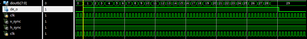
经与matlab运算结果做对比,结果完全一致。