HDLBits自学笔记3:Verilog language.Modules Hierarchy
Modules
在顶层模块中实例化模块mod_a,其端口描述:
module mod_a ( input in1, input in2, output out );

module top_module ( input a, input b, output out );
    // 按信号名称连线
    mod_a u1(
        .in1(a),
        .in2(b),
        .out(out)
    );
    // 按信号位置连线
    // mod_a u2(a, b, out);
endmodule
Connection ports by position
在顶层模块中按信号位置实例化模块mod_a,其端口描述:
module mod_a ( output, output, input, input, input, input );
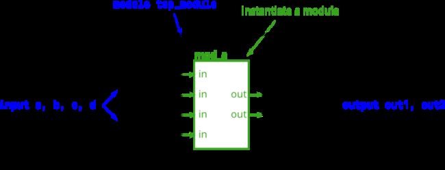
module top_module (
    input a,
    input b,
    input c,
    input d,
    output out1,
    output out2
);
    mod_a u_1(out1, out2, a, b, c, d);
endmodule
Connecting ports by name
在顶层模块中按信号名实例化mod_a,其端口描述:
module mod_a ( output out1, output out2, input in1, input in2, input in3, input in4);

module top_module (
    input a,
    input b,
    input c,
    input d,
    output out1,
    output out2
);
    mod_a u1(
        .in1 (a),
        .in2 (b),
        .in3 (c),
        .in4 (d),
        .out1(out1),
        .out2(out2)
    );
endmodule
Three modules
提供D触发器模块my_dff,实例化3个D触发器,链式连接它们实现一个3bit移位寄存器
D触发器my_dff的端口描述:module my_dff ( input clk, input d, output q );

module top_module ( input clk, input d, output q );
    wire q1, q2;
    my_dff u1(clk, d, q1);
    my_dff u2(clk, q1, q2);
    my_dff u3(clk, q2 ,q);
endmodule
Modules and vectors
提供8位D触发器my_dff8,实例化3个8位D触发器,链式连接它们,实现长度为3的8位移位寄存器,并实现一个4选1多路选择器,选择输出打0、1、2、3拍的输入信号
my_dff8的端口描述:my_dff8 ( input clk, input [7:0] d, output [7:0] q );
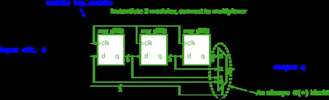
module top_module (
    input clk,
    input [7:0] d,
    input [1:0] sel,
    output reg [7:0] q
);
    wire [7:0] q1, q2, q3;
    my_dff8 u1(clk, d, q1);
    my_dff8 u2(clk, q1, q2);
    my_dff8 u3(clk, q2, q3);

    always @(*) begin
        case(sel)
            2'b00: q = d;
            2'b01: q = q1;
            2'b10: q = q2;
            2'b11: q = q3;
        endcase
    end
endmodule
Adder 1
提供16位加法器模块add16,实例化2个该模块,实现32位加法器,一个计算低16位,一个计算高16位
add16的端口描述:module add16 ( input[15:0] a, input[15:0] b, input cin, output[15:0] sum, output cout );

module top_module(
    input [31:0] a,
    input [31:0] b,
    output [31:0] sum
);
    wire cout;
    add16 u1(
        .a   (a[15:0]),
        .b   (b[15:0]),
        .cin (1'b0),
        .sum (sum[15:0]),
        .cout(cout)
    );
    add16 u2(
        .a   (a[31:16]),
        .b   (b[31:16]),
        .cin (cout),
        .sum (sum[31:16]),
        .cout()
    );
endmodule
Adder 2
编写1位全加器add1,系统会实例化16个1位全加器,实现16位加法器add16,在此基础上,实例化2个16位加法器,实现32位加法器:

module top_module (
    input [31:0] a,
    input [31:0] b,
    output [31:0] sum
);
    wire cout;
    add16 u1(
        .a   (a[15:0]),
        .b   (b[15:0]),
        .cin (1'b0),
        .sum (sum[15:0]),
        .cout(cout)
    );

    add16 u2(
        .a   (a[31:16]),
        .b   (b[31:16]),
        .cin (cout),
        .sum (sum[31:16]),
        .cout()
    );
endmodule

module add1 ( input a, input b, input cin,   output sum, output cout );
    assign cout = (a & b) | (b & cin) | (a & cin);
    assign sum = a ^ b ^ cin;
endmodule
Carry-select adder
行波进位加法器的缺点是延迟太大,每一个全加器都必须等待前一个全加器的进位产生,这导致加法器延迟大。
进位选择加法器是对此的一种改进,低16位加法器保持不变,高16位加法器实例化两个,一个假设低16位进位为0,一个假设为1,用2选1选择器选择使用哪个结果,如下图:
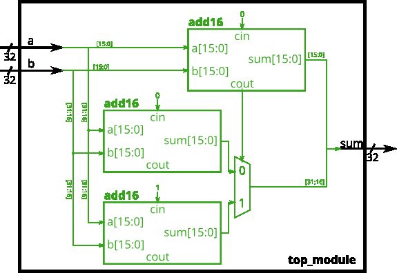
module top_module(
    input [31:0] a,
    input [31:0] b,
    output [31:0] sum
);
    wire low_cout;
    wire [15:0] high_sum0, high_sum1, high_sum;

    add16 low(
        .a    (a[15:0]),
        .b    (b[15:0]),
        .cin  (1'b0),
        .sum  (sum[15:0]),
        .cout (low_cout)
    );

    add16 high0(
        .a    (a[31:16]),
        .b    (b[31:16]),
        .cin  (1'b0),
        .sum  (high_sum0),
        .cout ()
    );

    add16 high1(
        .a    (a[31:16]),
        .b    (b[31:16]),
        .cin  (1'b1),
        .sum  (high_sum1),
        .cout ()
    );

    assign sum[31:16] = low_cout ? high_sum1 : high_sum0;
endmodule
Adder-subtractor
选择性的将加法器的一个输入反转,就能从加法器构建加减器,此时进位也为1,等同于反转后+1。一个加减器能够实现两种操作:(a + b + 0)或(a + ~b + 1),提供16位加法器add16,建立32位加减器。

module top_module(
    input [31:0] a,
    input [31:0] b,
    input sub,
    output [31:0] sum
);
    wire cout;
    add16 u0(
        .a   (a[15:0]),
        .b   ({16{sub}} ^ b[15:0]),// 异或有选择反相性
        .cin (sub),
        .sum (sum[15:0]),
        .cout(cout)
    );

    add16 u1(
        .a   (a[31:16]),
        .b   ({16{sub}} ^ b[31:16]),
        .cin (cout),
        .sum (sum[31:16]),
        .cout()
    );
endmodule