X86实模式到保护模式,分时多任务操作系统V0.0.1版本(完整代码)
前言
源码下载链接: X86实模式到保护模式,分时多任务操作系统V0.0.1版本(完整代码)
看到了自己以前写的代码,头晕, 想吐,想起了操作系统的那些事, 头就更疼了,为了将来不再头疼,就想记录下来,当然了, 这也是是一个学习操作系统很简单的小入门程序
本案例系统镜像由两部分组成:
第一部分是 loader.img,512字节, 由 loader.s汇编程序 编译而成,干两件事:
1) 将内核代码 从磁盘加载到内存。
2) 进入保护模式,实现到内核代码段的关键跳转,这一跳是头也不回的那种。
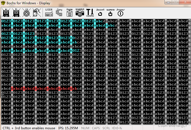
第二部分镜像就是内核代码start.img, 由 start.s, kernal.c ,kernal.h 编译而成, 镜像大小8K,事实上没那么大,就几行代码,是我硬是要她那么大,程序小点没啥关系,但占地方一定要大。主要功能是实现 分时多任务, 汇编文件主要处理 几个中断 iret, c 主要处理了用到的数据结构,包括 IDT表, LDT表,TSS, GDT表,以及这些结构的初始化工作, 还有就是 栈空间的初始化,本案例中,有两个任务,任务0打印 “0123”, 任务1打印 “abcd” , 一个任务 用到 两个栈,就是内核栈和用户栈, 就是 0特权和3特权下使用的栈。
一、引导
BIOS 会将我们硬盘的引导扇区512字节,自动加载到 内存 0x7c00 处, 然后在实模式下开始执行我们的引导代码。
二、引导代码 分析
1.将kernal 从第二个扇区开始 8K 大小加载进内存 0x10000地址
代码如下:
seg_7c00 = 0x07c0
seg_1000 = 0x1000
kernal_length=17                 ;; 8k
start:
	jmpi init_seg, #seg_7c00	;;; 段间跳转  跳完之后  cs = 0x07c0  eip = 0x5
init_seg:
	mov ax, cs					;;;  设置 几个段寄存器 为  0x07c0
	mov ds, ax
	mov ss, ax
	mov es, ax
	mov sp, #400				;;

copy_kernal_to_mem:             ;; 利用 bios 0x13中断,从硬盘拷贝数据进内存 0x10000
	mov dx, #0x0080
	mov cx, #0x0002
	mov ax, #seg_1000
	mov es, ax
	xor bx, bx
	mov ax, #0x200 + kernal_length
	int 0x13
	jnc stack_pop_es02	       ;; 成功之后 打印一串提示信息

stack_pop_es01:
	mov ax, #seg_7c00
	mov es, ax

error_info:
	push es
	mov cx, #28
	mov dx, #0x1004
	mov bx, #0x000C
	mov bp, #msg1
	mov ax, #0x1301
	int 0x10
	pop es

die: jmp die                  ;; 不成功就死这

stack_pop_es02:
	mov ax, #seg_7c00
	mov es, ax

success_info:
	push es
	mov cx, #30
	mov dx, #0x1004
	mov bx, #0x000C
	mov bp, #msg2
	mov ax, #0x1301
	int 0x10
	pop es
2.将kernal 从 0x10000地址拷贝到 0x0 地址
我们的程序是基于分段模式,在设置 IDT, TSS,人工设置返回堆栈的时候都要用到偏移地址,如果程序运行时地址不在0处,需要重新计算偏移地址, 显得很麻烦。
load_to_zero:
	cli											;; 关中断,不被打扰
	;;;;;; 内存拷贝;;;;
	mov ax, #seg_1000
	mov ds, ax
	xor ax, ax
	mov es,ax
	mov cx, #0x1000     						;; 4k次 * 2B = 8K
	sub si, si
	sub di, di
	rep
	movw
	;;;;;;; 下面开始为进入保护模式做准备;;;;;;;;;
	mov ax, #seg_7c00
	mov ds, ax
	;;;;;;;;; 设置 临时 gdt, 和idt
	lidt idt_48
	lgdt gdt_48

	;;;;; 进入实模式
	mov ax , #0x0001
	lmsw ax
	;;;;;; 跳转进 内核的代码段,就是 GDT[1] 那个描述符,基地址是 0,程序所在位置也是 0地址,kernal 的入口
	jmpi 0,8

msg1:
	.ascii "copy system to mem error.."
	.byte 13,10

msg2:
	.ascii "copy system to mem success.."
	.byte 13,10

idt_48:	.word 0
		.word 0xfc00, 0

gdt_48: .word 0x07ff
		.word 0x7c00 + gtd_tbl, 0

gtd_tbl:	.word 0,0,0,0
			.word 0x07ff
			.word 0x0000
			.word 0x9a00
			.word 0x00c0
			.word 0x07ff
			.word 0x0000
			.word 0x9200
			.word 0x00c0

.org 510
    .word 0xAA55				;;;;  呵呵
三、主程序 分析
1. 重新设置新的 IDT,LDT,TSS,GDT, 任务0和任务1的内核栈和用户栈
代码如下:
void setup_idt()
{
	Idt temp[256];
	int i;
	for (i = 0; i < 256; i++) {
		if ( i == 8) {
			Idt t  = idt_desc((int32)int_vec_08, 0x0008, 0x8E);
			temp[i] = t;
			continue;
		}
		if ( i == 128) {
			Idt t  = idt_desc((int32)int_vec_128, 0x0008, 0xef);
			temp[i] = t;
			continue;
		}
		Idt t = idt_desc((int32)int_ignore, 0x0008, 0x8E);
		temp[i] = t;
	}

	memcp(idt_tbl, temp, sizeof(temp));
    Idtr  idtr_value = { 256*8 , (char *)idt_tbl } ; // IDTR 寄存器
	idtr_value_assignment(&idtr_value);
}
void setup_ldt()
{
	Ldt temp0[] = {{0,0,0,0,0,0},
	{0x03ff, 0x0000, 0x00, 0xfa, 0xc0, 0x00},  // 0x0f    code-desc   任务0用户代码段
	{0x03ff, 0x0000, 0x00, 0xf2, 0xc0, 0x00}}; // 0x17	  data-desc  任务0用户数据段
	memcp(ldt0, temp0, sizeof(temp0));

	Ldt temp1[] = {{0,0,0,0,0,0},
	{0x03ff, 0x0000, 0x00, 0xfa, 0xc0, 0x00},  // 0x0f    code-desc   任务0用户代码段
	{0x03ff, 0x0000, 0x00, 0xf2, 0xc0, 0x00}}; // 0x17	  data-desc  任务0用户数据段
	memcp(ldt1, temp1, sizeof(temp1));
}

void setup_tss()
{
	 Tss ts0  = (Tss){ 0x0, (int32)tss0_kernal_stack  + 1024 , 0x10, 0x0, 0x0, 0x0, 0x0, 0x0,
			   (int32)task0, 0x200, 0x0,0x0,0x0,0x0, (int32)tss0_user_stack + 512, 0x0,0x0,0x0,
			  0x17, 0x0f, 0x17, 0x17, 0x17, 0x17, 0x28, 0x80000000
			};

	 Tss ts1 = (Tss){ 0x0, (int32)tss1_kernal_stack + 1024 , 0x10, 0x0, 0x0, 0x0, 0x0, 0x0,
				  (int32)task1, 0x200, 0x0,0x0,0x0,0x0, (int32)tss1_user_stack + 512 , 0x0,0x0,0x0,
				  0x17, 0x0f, 0x17, 0x17, 0x17, 0x17, 0x38, 0x80000000
				};

	memcp(&tss0, &ts0, sizeof(ts0));
	memcp(&tss1, &ts1, sizeof(ts1));
}


void setup_gdt()
{
	Gdt temp[8] = { {0,0,0,0,0,0},
	{0x07ff, 0x0000, 0x00, 0x9a, 0xc0, 0x00},				// 0x08   内核代码段    base = 0x10000
	{0x07ff, 0x0000, 0x00, 0x92, 0xc0, 0x00},				// 0x10	   base = 0x10000
	{0x0002, 0x8000, 0x0b, 0x92, 0xc0, 0x00},				// 0x18    内核显示区域  2*4k         base = 0xb8000
	{0x0068, (int32)(&tss0), 0x00, 0xe9, 0x00, 0x00},	    // 0x20     任务0的 段描述符        sizeof(TSS) = 0x68      base = 0x10000
	{0x0040, (int32)ldt0 , 0x00, 0xe2, 0x00, 0x00},         // 0x28   任务0的 LDT描述符       8*8=0x40 ldt最多8个表项 base = 0x10000
	{0x0068, (int32)(&tss1) , 0x00, 0xe9, 0x00, 0x00},		// 0x30   任务1的 TSS描述符
	{0x0040, (int32)ldt1, 0x00, 0xe2, 0x00, 0x00} };		// 0x38   任务1的 LDT描述符
	memcp(gdt_tbl, temp, sizeof(temp));

	Gdtr  gdtr_value = { 8*8  , (char *)gdt_tbl } ; // GDTR 寄存器
	gdtr_value_assignment(&gdtr_value);
}

void setup_8253()
{
	set_up_8253(0x36, 0x40, 11930);  // 100hz  1秒 100次中断, 时钟周期 1/100 s = 10ms
}
2. 从内核 空间 跳转进入用户空间,执行 任务0
主要利用 iret 中断返回指令,利用硬件工作原理, 人工设置返回堆栈,状态寄存器和 和cs:eip寄存器,跳转到任务0运行。
### GDT 选择子
gdt_scrn_selector=0x18      ####  0x18 ---> 二进制 [00011] [0][00]  特权级[00] 选择符[0]:GDT表  索引=[00011]= 3,GDT[3]
gdt_tss0_selector=0x20
gdt_ldt0_selector=0x28
gdt_tss1_selector=0x30
gdt_ldt1_selector=0x38
.global _start, int_ignore, int_vec_08,  int_vec_128, task0, task1

_start:
	movl $0x10, %eax							## 0x10 是GDT 表中的 数据段描述符
	mov %ax, %ds								## 初始化各种段
	mov %ax, %es
	mov %ax, %fs
	mov %ax, %gs
	lss init_stack, %esp						###  下面调用 C 函数要用到 栈,所以要先初始化栈

	call sys_init								## 调用C 初始化 IDT, LDT, TSS, GDT

	call setup_8253							    ### 初始化 8253 定时芯片,时间片实现原理

	;;;;;;; 准备从 内核态 进入 用户态 执行任务0
	pushfl
	andl $0xffffbfff, (%esp)					####  NF = 0, 关闭任务链
	popfl

	movl $gdt_tss0_selector, %eax				### 设置 任务0 的 tr 选择子
	ltr %ax
	movl $gdt_ldt0_selector, %eax				### 设置 任务0 的 ldt 选择子
	lldt %ax

	movl $0, current_task_no					## 设置当前任务0

	sti											## 中断使能,设置任务0的用户空间IF=1

	#######  在当前内核栈中 手工设置 iret 返回时候的五个寄存器
	pushl $0x17									## 任务0 ss
	movl  $tss0_user_stack, %eax				## 任务0 用户栈
	addl  $512, %eax
	pushl %eax
	pushfl										## 任务0 cs
	pushl $0x0f
	pushl $task0								## 任务0 eip

	iret										##  cs:eip=0x0f:task0, ss:esp=0x17:用户栈地址
3. 中断处理
时钟中断 int 0x8 , 系统中断 int 0x80,中断的原理这里不再赘述。
int_ignore:
    pushl $_do_int_ignore
    jmp _int_wrapper

int_vec_08:
    pushl $_do_int_vec_08
    jmp _int_wrapper

int_vec_128:
	pushl $_do_int_vec_128
    jmp _int_wrapper

_do_int_ignore:
	movl $67, %eax
	call write_char
	ret

_do_int_vec_08:
	movb $0x20, %al
	outb %al, $0x20
	movl $1, %eax
	cmpl %eax, current_task_no
	je 1f
	movl %eax, current_task_no
	ljmp $gdt_tss1_selector, $0						## 保存 tss0, 运行  tss1,  切换到tss1的堆栈
	jmp 2f
1:  movl $0, current_task_no
	ljmp $gdt_tss0_selector, $0
2:	ret


_do_int_vec_128:
	call write_char
	ret

###	中断发生 软件处理的 寄存器 出入栈
_int_wrapper:
	xchgl %ecx,(%esp)		 		# &function  ---> ecx
	pushl %ebx
	pushl %eax
	pushl %edx
	pushl %edi
	pushl %esi
	pushl %ebp
	push  %ds
	push  %es
	push  %fs
	push  %gs
	movl $0x10, %edx
	mov %dx, %ds
	mov %dx, %es
	mov %dx, %fs
	call *%ecx
	pop  %gs
	pop  %fs
	pop  %es
	pop  %ds
	popl %ebp
	popl %esi
	popl %edi
	popl %edx
	popl %eax
	popl %ebx
	popl %ecx
	iret
效果演示:
项目完成源码下载地址: https://download.csdn.net/download/u010209554/86246383