【FPGA】串口通信讲解-状态机判断数据值
欢迎来到FPGA专栏~串口通信讲解
- ☆* o(≧▽≦)o *☆嗨~我是小夏与酒
- ✨博客主页:小夏与酒的博客
- 该系列文章专栏:FPGA学习之旅
- 文章作者技术和水平有限,如果文中出现错误,希望大家能指正
- 欢迎大家关注! ❤️


目录-串口通信讲解
- 一、效果演示
- 二、串口通信基础知识
- 三、基本通信代码编写
-
- 3.1 异步信号分析
- 3.2 USB
- 3.3 RS232
- 3.4 串口接收模块
- 3.5 串口发送模块
- 四、串口通信控制led亮灭

一、效果演示
视频演示:
FPGA串口通信控制led点亮与熄灭
RTL视图:
顶层模块:

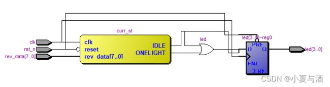
状态机判断数据值:
二、串口通信基础知识
参考【小月电子】大佬的博客:【小月电子】ALTERA FPGA开发板系统学习教程-LESSON7串口通信。
UART 是一种采用异步串行通信方式的通用异步收发传输器(universal asynchronous receiver-transmitter),它在发送数据时将并行数据转换成串行数据来传输,在接收数据时将接收到的串行数据转换成并行数据。
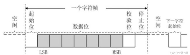
UART 串口通信需要两根信号线来实现,一根用于串口发送,另外一根负责串口接收。UART 在发送或接收过程中的一帧数据由 4 部分组成,起始位、数据位、奇偶校验位和停止位。其中,起始位标志着一帧数据的开始,停止位标志着一帧数据的结束,数据位是一帧数据中的有效数据。校验位分为奇校验和偶校验,用于检验数据在传输过程中是否出错。奇校验时,发送方应使数据位中 1 的个数与校验位中 1 的个数之和为奇数;接收方在接收数据时,对 1 的个数进行检查,若不为奇数,则说明数据在传输过程中出了差错。同样,偶校验则检查 1 的个数是否为偶数。
串口通信的速率用波特率表示,它表示每秒传输二进制数据的位数,单位是 bps( 位/秒),常用的波特率有 9600、19200、38400、57600 以及 115200 等。
在本篇文章中,串口通信所使用的波特率为9600,计算过程:
1、板载晶振为50MHz,时钟周期为20ns;
2、波特率9600bps表示每秒传输9600bit;
3、传输1bit的时间为:1/9600(秒)=104167ns;
4、104167/20=5208.35,也就是5208个时钟周期,需要采集1次。
在异步串口时序图中,空闲时为高电平,起始位为低电平,停止为高电平:
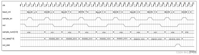
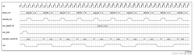
串口接收时序图:
串口发送时序图:
三、基本通信代码编写
3.1 异步信号分析
参考链接:高级FPGA设计技巧!多时钟域和异步信号处理解决方案。
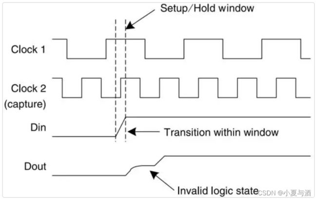
亚稳态:
触发器的建立时间和保持时间在时钟上升沿左右定义了一个时间窗口,如果触发器的数据输入端口上数据在这个时间窗口内发生变化(或者数据更新),那么就会产生时序违规。存在这个时序违规是因为建立时间要求和保持时间要求被违反了,此时触发器内部的一个节点(一个内部节点或者要输出到外部节点)可能会在一个电压范围内浮动,无法稳定在逻辑0或者逻辑1状态。换句话说,如果数据在上述窗口中被采集,触发器中的晶体管不能可靠地设置为逻辑0或者逻辑1对应的电平上。所以此时的晶体管并未处于饱和区对应的高或者低电平,而是在稳定到一个确定电平之前,徘徊在一个中间电平状态(这个中间电平或许是一个正确值,也许不是)。如下图所示,这就是所谓的亚稳态:
解决亚稳态的方法之一就是打两拍处理:
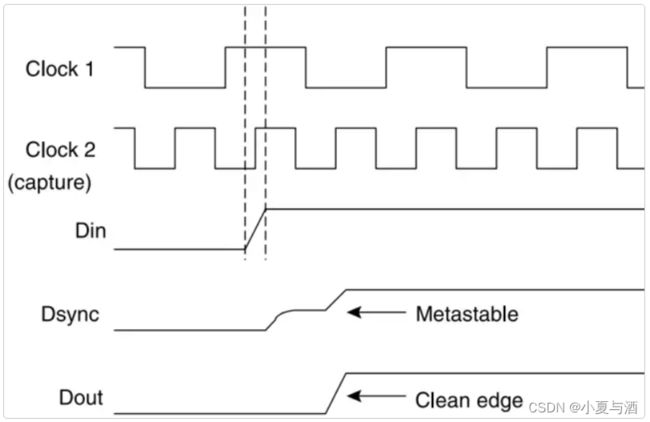
处理实现代码:
reg	rxd_ff1;
reg	rxd_ff2;
//打两拍操作-第一拍
always@(posedge clk or negedge rst_n)begin
	if(!rst_n)
		rxd_ff1 <= 1'b0;
	else
		rxd_ff1 <= rxd;
end
//打两拍操作-第二拍
always@(posedge clk or negedge rst_n)begin
	if(!rst_n)
		rxd_ff2 <= 1'b0;
	else
		rxd_ff2 <= rxd_ff1;
end
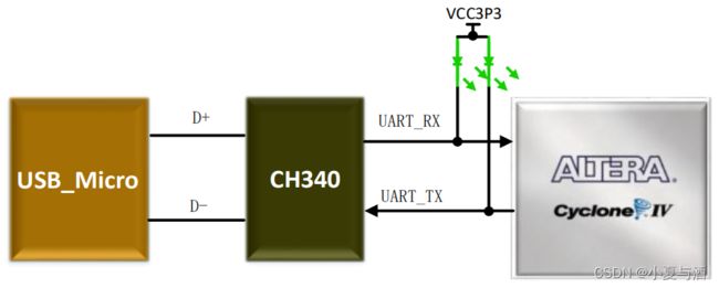
3.2 USB
硬件电路:
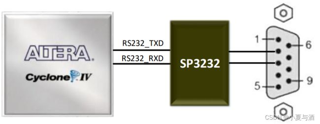
3.3 RS232
硬件电路:
3.4 串口接收模块
async_uart_rev.v:
///
//模块介绍:实现异步串口接收功能
///
module async_uart_rev(
	input				rst_n	,//复位信号,低电平有效
	input				clk,//时钟信号,50MHZ
	input				rxd,//串行接收数据
	output	reg	[7:0]	rev_data,//并行数据
	output	reg			rev_dvld //并行数据有效标志
	);

	parameter	baud_num	=5207;//1/9600*1000000000/20
	parameter	IDLE		=4'd0;
	parameter	START_ST    =4'd1;
	parameter	STOP_ST     =4'd2;

	reg	[12:0]	baud_cnt;
	reg			baud_cnt_en;
	wire		sample_en;
	reg	[3:0]	sample_num;
	reg			rxd_ff1;
	reg			rxd_ff2;
	reg	[3:0]	curr_st;

	//打两拍操作-第一拍
	always@(posedge clk or negedge rst_n)begin
		if(!rst_n)
			rxd_ff1 <= 1'b0;
		else
			rxd_ff1 <= rxd;
	end
	//打两拍操作-第二拍
	always@(posedge clk or negedge rst_n)begin
		if(!rst_n)
			rxd_ff2 <= 1'b0;
		else
			rxd_ff2 <= rxd_ff1;
	end

	//sample_en判断计数器是否到达计数值
	assign sample_en = (baud_cnt == baud_num[12:1])?1'b1:1'b0;

	//状态机跳转程序
	always@(posedge clk or negedge rst_n)begin
		if(!rst_n)
			curr_st<=IDLE;
		else case(curr_st)
			IDLE:begin
				if(rxd_ff2==0)
					curr_st<=START_ST;
				else
					;
			end
			START_ST:begin
				if(sample_num==8&&sample_en)
					curr_st<=STOP_ST;
				else
					;
			end
			STOP_ST:begin
				if(rxd_ff2==1&&sample_en)
					curr_st<=IDLE;
				else
					;
			end
			default:;
		endcase
	end

	//baud_cnt波特率计数器
	always@(posedge clk or negedge rst_n)begin
		if(!rst_n)
			baud_cnt<=0;
		else if(curr_st==START_ST||curr_st==STOP_ST)begin
			if(baud_cnt==baud_num)
				baud_cnt<=0;
			else
				baud_cnt<=baud_cnt+1;
		end else
			baud_cnt<=0;
	end

	always@(posedge clk or negedge rst_n)begin
		if(!rst_n)
			sample_num<=0;
		else if(sample_en&&sample_num==9)
			sample_num<=0;
		else if(sample_en)
			sample_num<=sample_num+1;
		else
			;
	end

	always@(posedge clk or negedge rst_n)begin
		if(!rst_n)
			rev_data<=0;
		else if(sample_en)
			case(sample_num)
			1:rev_data[0]<=rxd_ff2;
			2:rev_data[1]<=rxd_ff2;
			3:rev_data[2]<=rxd_ff2;
			4:rev_data[3]<=rxd_ff2;
			5:rev_data[4]<=rxd_ff2;
			6:rev_data[5]<=rxd_ff2;
			7:rev_data[6]<=rxd_ff2;
			8:rev_data[7]<=rxd_ff2;
			default:;
		endcase
	end

	always@(posedge clk or negedge rst_n)begin
		if(!rst_n)
			rev_dvld<=0;
		else if(sample_num==9&&sample_en)
			rev_dvld<=1;
		else
			rev_dvld<=0;
	end

endmodule
3.5 串口发送模块
async_uart_tran.v:
///
//模块介绍:实现异步串口发送功能
///
module async_uart_tran(
	input				rst_n	,//复位信号,低电平有效
	input				clk,//时钟,50MHZ
	input		[7:0]	tran_data,//输入的并行数据
	input				tran_dvld,//输入的并行数据有效标志
	output		reg		txd      //串行输出数据
	);

	parameter	baud_num	=5207;//1/9600*1000000000/20
	parameter	IDLE		=4'd0;
	parameter	DATA_ST    	=4'd1;
	parameter	START_ST    =4'd2;
	parameter	STOP_ST     =4'd3;

	reg	[12:0]		baud_cnt;
	reg				baud_cnt_en;
	reg	[3:0]		sample_num;
	reg	[3:0]		curr_st;

	wire		sample_en;

	assign	sample_en = (baud_cnt==baud_num)?1'b1:1'b0;

	always@(posedge clk or negedge rst_n)begin
		if(!rst_n)
			curr_st<=IDLE;
		else case(curr_st)
			IDLE:begin
				if(tran_dvld==1)
					curr_st<=START_ST;
				else
					;
			end
			START_ST:begin
				if(sample_en==1)
					curr_st<=DATA_ST;
			end
			DATA_ST:begin
				if(sample_en&&sample_num==8)
					curr_st<=STOP_ST;
				else
					;
			end
			STOP_ST:begin
				if(sample_en==1)
					curr_st<=IDLE;
				else
					;
			end
			default:;
		endcase
	end

	always@(posedge clk or negedge rst_n)begin
		if(!rst_n)
			baud_cnt<=0;
		else if(curr_st==START_ST||curr_st==DATA_ST||curr_st==STOP_ST)begin
			if(baud_cnt==baud_num)
				baud_cnt<=0;
			else
				baud_cnt<=baud_cnt+1;
		end else
			baud_cnt<=0;
	end

	always@(posedge clk or negedge rst_n)begin
		if(!rst_n)
			sample_num<=0;
		else if(curr_st==IDLE)
			sample_num<=0;
		else if(sample_en)
			sample_num<=sample_num+1;
		else
			;
	end

	always@(posedge clk or negedge rst_n)begin
		if(!rst_n)
			txd<=1;
		else if(sample_en)
			case(sample_num)
			0:txd<=1'b0;
			1:txd<=tran_data[0];
			2:txd<=tran_data[1];
			3:txd<=tran_data[2];
			4:txd<=tran_data[3];
			5:txd<=tran_data[4];
			6:txd<=tran_data[5];
			7:txd<=tran_data[6];
			8:txd<=tran_data[7];
			9:txd<=1'b1;
			default:txd<=1;
		endcase
	end

endmodule
四、串口通信控制led亮灭
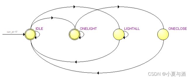
使用状态机判断数据并控制led亮灭:
状态机学习参考链接:【FPGA零基础学习之旅#9】状态机基础知识。
主要根据状态跳转来编写代码:

data.v:
module data(
	input 				clk,
	input 				rst_n,
	input 		[7:0]	rev_data,
	output reg 	[3:0]	led
);

	//定义LED的亮灭
	parameter led_light_all = 8'h11;//全部点亮
	parameter led_close_all = 8'h00;//全部熄灭
	parameter led_light_one = 8'hAA;//点亮led1
	parameter led_close_one = 8'hFF;//关闭led1

	localparam
		IDLE 	 = 4'b0001,
		LIGHTALL = 4'b0010,
		ONELIGHT = 4'b0100,
		ONECLOSE = 4'b1000;

	reg [3:0]curr_st;

	//状态机主程序
	always@(posedge clk or negedge rst_n)begin
		if(!rst_n)
			curr_st <= IDLE;
		else begin
			case(curr_st)
				IDLE:begin
					if(rev_data == led_light_all)
						curr_st <= LIGHTALL;
					else if(rev_data == led_light_one)
						curr_st <= ONELIGHT;
					else
						;
				end
				LIGHTALL:begin
					if(rev_data == led_close_all)
						curr_st <= IDLE;
					else
						;
				end
				ONELIGHT:begin
					if(rev_data == led_close_one)
						curr_st <= ONECLOSE;
					else
						;
				end
				ONECLOSE:curr_st <= IDLE;
			default:curr_st <= IDLE;
			endcase
		end
	end

	always@(posedge clk or negedge rst_n)begin
		if(!rst_n)
			led <= 4'b1111;
		else begin
			case(curr_st)
				IDLE:		led <= 4'b1111;
				LIGHTALL:led <= 4'b0000;
				ONELIGHT:led <= 4'b1110;
				ONECLOSE:led <= 4'b0000;
			default:led <= led;
			endcase
		end
	end

endmodule
data.v的RTL视图:

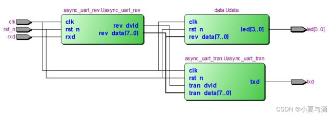
本篇文章实现的顶层模块:
///
//模块介绍:顶层模块,例化接收和发送模块,控制LED状态
///
module async_uart_top(
	input			clk		,//时钟,50MHZ
	input			rst_n		,//复位信号,低电平有效
	input			rxd		,//串行接收数据
	output			txd		,//串行发送数据
	output	[3:0] 	led
	);

	wire	[7:0]	rev_data;
	wire			rev_dvld;

	async_uart_rev Uasync_uart_rev(
		.rst_n(rst_n),
		.clk(clk),
		.rxd(rxd),
		.rev_data(rev_data),
		.rev_dvld(rev_dvld)
	);

	async_uart_tran Uasync_uart_tran(
		.rst_n(rst_n),
		.clk(clk),
		.tran_data(rev_data),
		.tran_dvld(rev_dvld),
		.txd(txd)
	);

	data Udata(
		.clk(clk),
		.rst_n(rst_n),
		.rev_data(rev_data),
		.led(led)
	);

endmodule
顶层模块的RTL视图:
结尾
- ❤️ 感谢您的支持和鼓励!
- 您可能感兴趣的内容:
- 【Python】Python实现串口通信(Python+Stm32)
- 【Verilog HDL】FPGA-testbench基础知识
- 【Arduino TinyGo】【最新】使用Go语言编写Arduino-环境搭建和点亮LED灯
- 【全网首发开源教程】【Labview机器人仿真与控制】Labview与Solidworks多路支配关系-四足爬行机器人仿真与控制
