【AutoSAR 架构介绍】
AutoSAR简介
AUTOSAR是Automotive Open System Architecture(汽车开放系统架构)的首字母缩写,是一家致力于制定汽车电子软件标准的联盟。
AUTOSAR是由全球汽车制造商、部件供应商及其他电子、半导体和软件系统公司联合建立,各成员保持开发合作伙伴关系。
自2003年起,各伙伴公司携手合作,致力于为汽车工业开发一个开放的、标准化的软件架构。AUTOSAR这个架构有利于车辆电子系统软件的交换与更新,并为高效管理愈来愈复杂的车辆电子、软件系统提供了一个基础。
此外,AUTOSAR在确保产品及服务质量的同时,提高了成本效率。整车软件系统可通过AUTOSAR架构对车载网络、系统内存及总线的诊断功能进行深度管理,它的出现有利于整车电子系统软件的更新与交换,并改善了系统的可靠性和稳定性。
目前支持AUTOSAR标准的工具和软件供应商都已经推出了相应的产品,提供需求管理,系统描述,软件构件算法模型验证,软件构建算法建模,软件构件代码生成,RTE生成,ECU配置以及基础软件和操作系统等服务,帮助OEM实现无缝的系统软件架构开发流程。
AUTOSAR计划目标主要有三个:1)建立独立于硬件的分层软件架构;2)为实施应用提供方法论,包括制定无缝的软件架构堆叠流程并将应用软件整合至ECU;3)制定各种车辆应用接口规范,作为应用软件整合标准,以便软件构件在不同汽车平台复用。
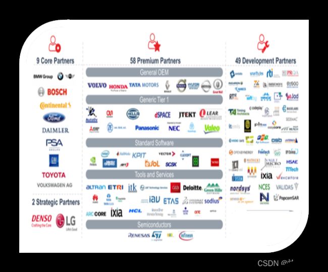
 AutoSar伙伴
核心合作伙伴(9)
宝马、大众、戴姆勒、PSA、博世、大陆集团、福特,通用汽车、丰田
高级合作伙伴(58+)
沃尔沃汽车、本田、长城、矢量,Mentor Graphics
。。。。
发展合作伙伴(49+)
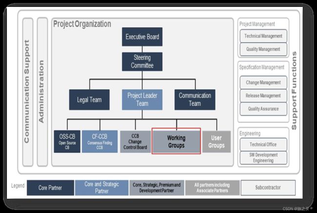
AutoSar组织
工作组的工作重点如下:
指定AUTOSAR运行时环境,以提供车辆网络所有节点之间的ECU内部和内部通信。
定义基本软件模块和汽车操作系统领域现有解决方案的需求和分析。
定义方法和数据交换格式,以描述车辆E/E系统架构的交换相关元素。
定义AUTOSAR运行时环境的API和服务接口。
定义不同车辆领域的标准化接口。
定义验收测试。
集成自适应平台的示例AUTOSAR软件实现。
成员包括核心、高级和发展合作伙伴以及与会者,他们代表了来自各个领域的合作伙伴的广泛知识和经验。
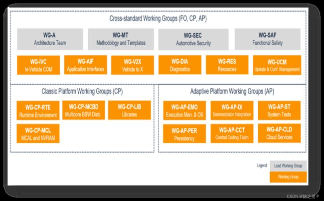
AutoSar Working Groups
所有活动都被分配用于开发和维护经典平台、自适应平台、验收测试、应用程序接口和跨标准功能。
AutoSar标准
Classic Platform (CP)
Classic Platform 是AUTOSAR为具有严格实时性和安全性约束的嵌入式系统提供的解决方案。
软件体系结构概述(CP)
自适应平台是AUTOSAR的高性能计算ECU解决方案,用于为自动驾驶等用例构建故障操作系统。
软件体系结构内容(CP)
经典平台和自适应平台的通用部分作为一个名为AUTOSAR Foundation的单独标准发布。
公共部分是例如总线协议和方法的公共方面。
AUTOSAR验收测试是总线级和应用程序级的系统测试,用于验证AUTOSAR堆栈相对于应用软件组件和通信总线的行为。
AUTOSAR在以下五个车辆领域的语法和语义方面标准化了大量应用程序接口:车身和舒适性、动力传动系统发动机、动力传动系变速器、底盘控制以及乘员和行人安全。
CLASSIC平台与ADAPTIVE平台技术特性比较
| CLASSIC PLATFORM |
ADAPTIVE PLATFORM |
| Operating system based on OSEK |
Operating system based on POSIX (PSE51 with optional extensions) |
| Execution of code directly from ROM |
Application is loaded from persistent memory into RAM |
| Same address space for all applications (MPU support for safety) |
Each application has its own (virtual) address space (MMU support) |
| Optimized for signal-based communication (CAN, FlexRay) |
Designed for service-oriented communication |
| Fixed task configuration |
Support of multiple dynamic scheduling strategies |
| Specification |
Specification and code |
AP和CP并不是完全独立的。例如,基于AP的ECU和基于CP的ECU可以连接到同一个网络,因此二者均需要与各种通信协议兼容。除此之外,在系统设计信息等交付形式上,若AP/CP也没有达成一致的话,将会有更多的麻烦,特别是对车企一方来说,他们的管理会变得更加复杂。所以,AP和CP之间还是有很多共同点的!
把这些共同的部分截取出来,我们将其定义被称为Foundation (FO)标准组。
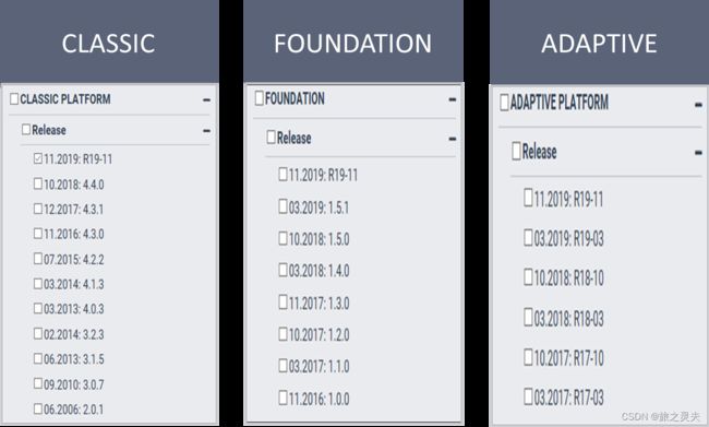
AUTOSAR RoadMap
软件架构概述(CP)
架构层概述
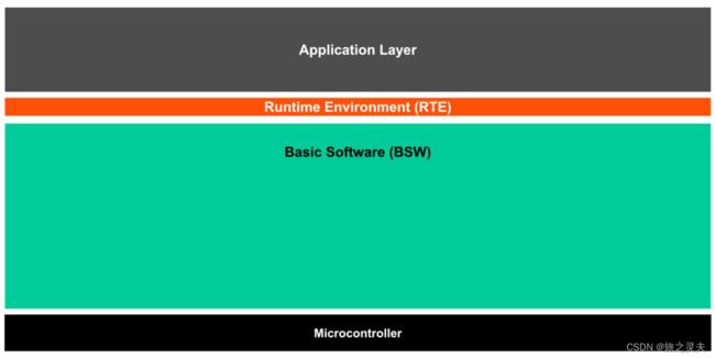
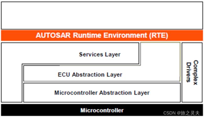
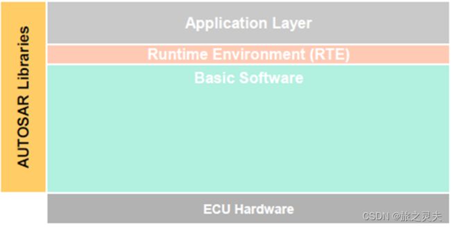
AUTOSAR架构在最高抽象级别上区分了三个软件层:应用程序、运行时环境和在微控制器上运行的基本软件。
分层软件体系结构描述了AUTOSAR的软件架构:
它以自上而下的方法描述了AUTOSAR软件的层次结构,将基本软件模块映射到软件层并显示它们的关系。
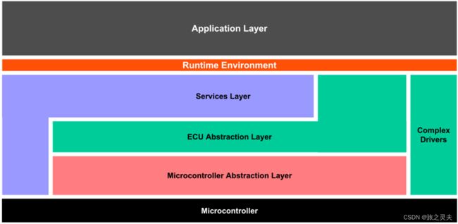
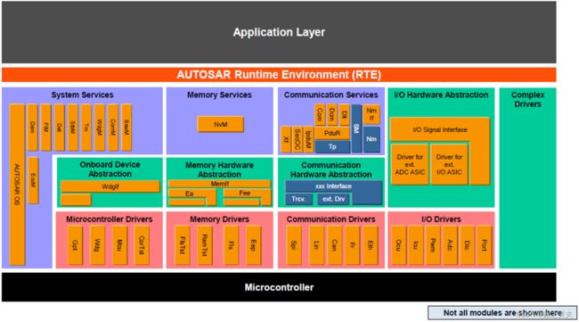
AUTOSAR基础软件进一步分为服务层、ECU抽象层、微控制器抽象层和复杂驱动层。
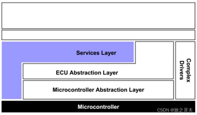
• 服务层(Service Layer),这一层基础软件提供了汽车ECU非应用相关的服务,包括OS,网络通讯,内存管理(NVRAM),诊断(UDS,故障管理等),ECU状态管理模块等,它们对ECU的应用层功能提供辅助支持,这一层软件在不同领域的ECU中也非常相似,例如不同的ECU中的OS的任务周期和优先级不同,不同的ECU中的NVRAM的分区不同,存储的内容不同。
• ECU抽象层(ECU Abstract Layer),这一层软件提供了ECU应用相关的服务,它是对一个ECU的抽象,它包括了所有的ECU的输入输出,比如AD,DIO,PWM等,这一层软件直接实现了ECU的应用层功能,可以读取传感器状态,可以控制执行器输出,不同领域的ECU会有很大的不同。
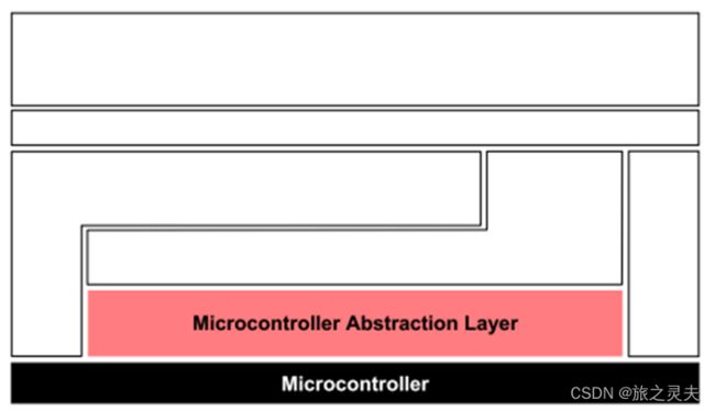
• MCAL(Microcontroller Absstraction Layer),这一层软件是对ECU所使用的主控芯片的抽象,它跟芯片的实现紧密相关,是ECU软件的最底层部分,直接和主控芯片及外设芯片进行交互,它的作用是将芯片提供的功能抽象成接口,然后把这些接口提供给上边的服务层/ECU抽象层使用。
• 复杂驱动(Complex Drivers),汽车ECU中有一些领域的ECU会处理相当复杂的硬件信号,执行相当复杂的硬件动作,例如发动机控制,ABS等,这些功能相关的软件很难抽象出来适用于所有的汽车ECU,它是跟ECU的应用以及ECU所使用的硬件紧密相关的,属于AUTOSAR构架中在不同的ECU上无法移植的部分。
最下层
可直接访问内部外围设备的驱动程序。
- 通信驱动器(SPI、CAN)
- I/O驱动器(ADC、PWM、DIO)
- 存储器驱动程序(闪存、EEPROM)
- 微控制器驱动程序(SPI,通用定时器)
取决于微控制器
任务
- 使更高的软件层独立于μC
属性
- 实现:取决于μC
- 上接口:标准化和μC
- 独立的
微控制器抽象层驱动程序接口
访问外围设备和设备的API
- 微控制器
- 内部的
- 外部的
服务层是基础的最高层
同样适用于应用软件相关性的软件:虽然ECU抽象层涵盖了对I/O信号的访问,但服务层提供:
- 操作系统功能
- 车辆网络通信和管理服务
- 内存服务(NVRAM管理)
- 诊断服务(包括UDS通信、错误记忆和故障处理)
- ECU状态管理、模式管理
- 必然的
任务
为应用程序、RTE和基本软件模块提供基本服务。
属性
实现:大部分μC和ECU硬件独立
上层接口:μC和ECU硬件独立
RTE是为应用软件(AUTOSAR软件组件和/或AUTOSAR传感器/执行器组件)提供通信服务的层。
- 在RTE之上,软件体系结构风格从“分层”变为“组件风格”。
- AUTOSAR软件组件通过RTE与其他组件(ECU间和/或ECU内)和/或服务进行通信。
复杂驱动程序层的范围从硬件到RTE。
- AUTOSAR中未指定的硬件
提供集成专用功能的可能性,例如设备驱动程序:
- 其未在AUTOSAR内指定,
- 具有非常高的时序约束,或者
- 用于迁移目的等。
属性
实现:可能取决于应用程序、μC和ECU硬件
上层接口:可能是应用程序,μC和ECU硬件相关
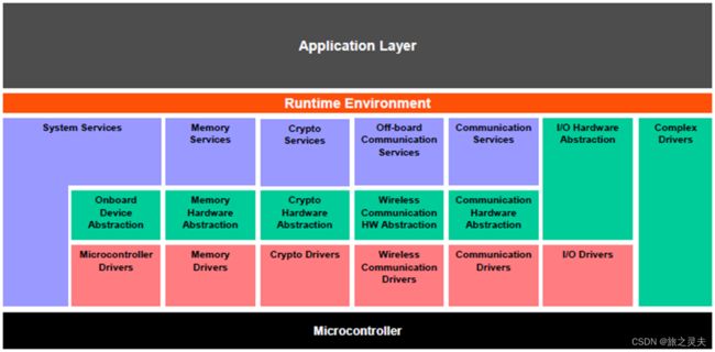
基础软件层被进一步划分为功能组。服务的例子有系统、内存和通信服务。
输入/输出(I/O)
对传感器、执行器和ECU车载外围设备的标准化访问
记忆力
对内部/外部存储器(非易失性存储器)的标准化访问
加密
对加密原语的标准化访问,包括内部/外部硬件加速器
表达
标准化访问:车辆网络系统、ECU车载通信系统和ECU内部软件
车外通信
标准化接入:车载通信、车载无线网络系统、ECU车外通信系统
系统
提供标准化(操作系统、计时器、错误存储器)和ECU特定(ECU状态管理、看门狗管理器)服务和库功能
驱动程序包含控制和访问内部或外部设备的功能。
内部设备位于微控制器内部。内部设备示例如下:
- 内部EEPROM
- 内部CAN控制器
- 内部ADC
内部设备的驱动程序称为内部驱动程序,位于微控制器抽象层。
外部设备位于微控制器外部的ECU硬件上。外部设备的示例包括:
- 外部EEPROM
- 外部看门狗
- 外部闪光灯
用于外部设备的驱动器被称为外部驱动器,并且位于ECU抽象层中。它通过微控制器抽象层的驱动程序访问外部设备。
通过这种方式,AUTOSAR还支持集成在系统基础芯片(SBC)中的组件,如收发器和看门狗。
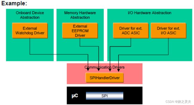
示例:具有SPI接口的外部EEPROM的驱动程序访问外部
EEPROM通过SPI总线的处理器/驱动器。
例外情况:
用于存储器映射的外部设备(例如,外部闪存)的驱动器可以直接访问微控制器。这些外部驱动器位于微控制器抽象层中,因为它们依赖于微控制器。
接口(接口模块)包含从架构上位于其下方的模块中抽象的功能。例如,从特定设备的硬件实现中抽象出来的接口模块。它提供了一个通用API来访问特定类型的设备,该设备独立于该类型现有设备的数量,并独立于不同设备的硬件实现。
该接口不会更改数据的内容。
通常,接口位于ECU抽象层中。
示例:CAN通信系统的接口提供了一个通用API,用于访问CAN通信网络,该网络独立于ECU内CAN控制器的数量,并且独立于硬件实现(片上、片外)。
处理程序是一个特定的接口,它控制一个或多个客户端对一个或更多驱动程序的并发、多个和异步访问。也就是说,它执行缓冲、排队、仲裁和多路复用。
处理程序不会更改数据的内容。
处理程序功能通常包含在驱动程序或接口中(例如SPIHandlerDriver、ADC驱动程序)。
经理为多个客户提供特定的服务。在纯处理程序功能不足以从多个客户端进行抽象的所有情况下,都需要它。
除了处理程序功能外,管理器还可以评估、更改或调整数据的内容。
通常,管理器位于服务层
示例:NVRAM管理器管理对内部和/或外部存储器设备(如闪存和EEPROM存储器)的并发访问。它还执行分布式和可靠的数据存储、数据检查、提供默认值等。
Libraries是用于相关目的的函数集合
- 可以由BSW模块(包括RTE)、SW C、库调用
- 在同一保护环境中的调用方上下文中运行
- 只能调用库
- 重新进入
- 没有内部状态
- 不需要任何初始化
- 是同步的
AUTOSAR中指定了以下库:
- 不动点数学,
- 浮点数学,
- 定点数据的插值,
- 浮点数据的插值,
- 比特处理,
- E2E通信,
- CRC计算,
- 扩展功能(例如64位计算、滤波等)
软件架构内容 (CP)
BSW 模块
有100多个基本软件模块。
抽象层
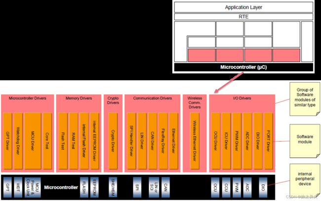
μC抽象层由以下模块组组成:
- 微控制器驱动程序
- 通信驱动程序
- 内存驱动程序
- I/O驱动程序
- 加密驱动程序
- 无线通信驱动程序
μC抽象层由以下模块组组成:
微控制器驱动程序
内部外围设备的驱动程序(例如看门狗、通用定时器)
具有直接μC访问的功能(例如核心测试)
通信驱动程序
车载ECU(例如SPI)和车辆通信(例如CAN)的驱动器。
OSI层:数据链路层的一部分
内存驱动程序
片上存储器设备(如内部闪存、内部EEPROM)和存储器映射外部存储器设备的驱动程序
(例如外部闪存)
I/O驱动程序:模拟和数字I/O驱动器(例如ADC、PWM、DIO)
SHE或HSM等芯片加密设备的加密驱动程序
无线通信驱动程序:无线网络系统的驱动程序(车内或车外通信)
SPIHandlerDriver是μC抽象层的一个组件,它允许多个客户端同时访问一条或多条SPI总线。
SPIHandlerDriver允许多个客户端同时访问一条或多条SPI总线。
为了抽象专用于芯片选择的SPI微控制器引脚的所有特征,这些特征应由SPIHandlerDriver直接处理。
这意味着这些引脚在DIO驱动器中不可用。
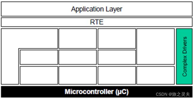
复杂驱动
复杂驱动程序是在基本软件堆栈中实现非标准化功能的模块。
- SW Cs的上层接口:根据AUTOSAR(AUTOSAR接口)规定和实现
- 下层接口:限制访问标准化接口
任务:
满足处理复杂传感器和执行器的特殊功能和时间要求
属性:
实现:高度依赖于μC、ECU和应用程序
SW Cs的上层接口:根据AUTOSAR(AUTOSAR接口)规定和实现
下层接口:限制访问标准化接口
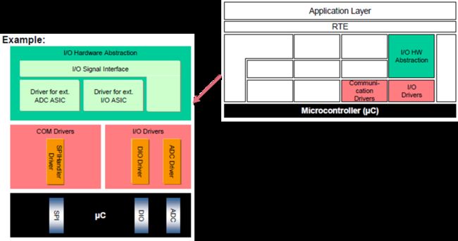
I/O硬件抽象
I/O硬件抽象是一组从外围I/O设备(片上或板上)的位置和ECU硬件布局(例如μC引脚连接和信号电平反转)中抽象出来的模块。
表示连接到ECU硬件的I/O信号(例如电流、电压、频率)。
从更高的软件层隐藏ECU硬件和布局属性。
Communication Hardware Abstraction
通信硬件抽象是从通信控制器的位置和ECU硬件布局中抽象出来的一组模块。对于所有通信系统,都需要特定的通信硬件抽象(例如LIN、CAN、FlexRay)。
示例:ECU有一个带2个内部CAN通道的微控制器和一个带4个CAN控制器的附加板载ASIC。CAN-ASIC通过SPI连接到微控制器。
通过总线专用接口(例如CAN接口)访问通信驱动程序。
任务:
提供平等的机制来访问总线通道,无论其位置如何(芯片上/板上)
属性:
实现:μC无关,ECU硬件相关,外部设备相关
上层接口:总线相关,μC和ECU硬件无关
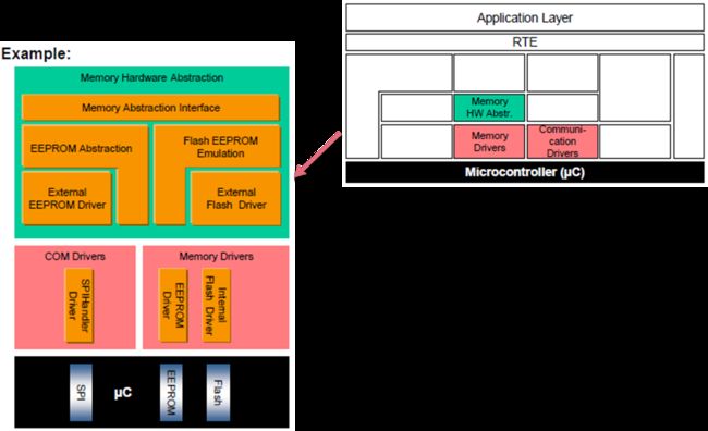
Memory Hardware Abstraction
存储器硬件抽象是一组从外围存储器设备(片上或板上)的位置和ECU硬件布局中抽象出来的模块。
示例:片上EEPROM和外部EEPROM设备可以通过相同的机制访问。
存储器驱动程序通过存储器专用抽象/仿真模块(例如EEPROM抽象)访问。
通过在闪存硬件单元上模拟EEPROM抽象,可以通过存储器抽象接口对这两种类型的硬件进行公共访问。
任务:
提供访问内部(芯片上)和外部(板载)存储器设备以及存储器硬件类型(EEPROM、闪存)的同等机制。
属性:
实现:μC独立,外部设备相关
上层接口:μC,ECU硬件和存储设备独立
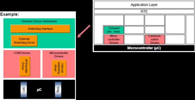
Onboard Device Abstraction
车载设备摘要包含ECU车载设备的驱动程序,这些设备不能被视为传感器或执行器,如内部或外部看门狗。这些驱动程序通过μC抽象层访问ECU车载设备。
任务:
ECU专用车载设备摘要。
属性:
实现:μC独立,外部设备相关
上层接口:μC独立,部分依赖ECU硬件
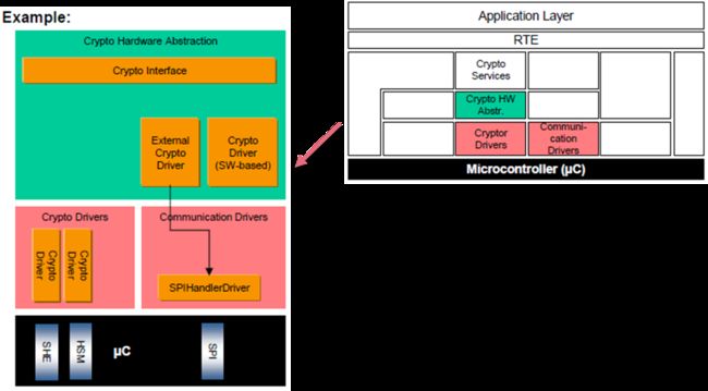
Crypto Hardware Abstraction
加密硬件抽象是一组从加密原语(基于内部或外部硬件或软件)的位置进行抽象的模块。
任务:
提供平等的机制来访问内部(芯片上)和软件加密设备。
属性:
实现:μC无关
上层接口:μC、ECU硬件和加密设备独立
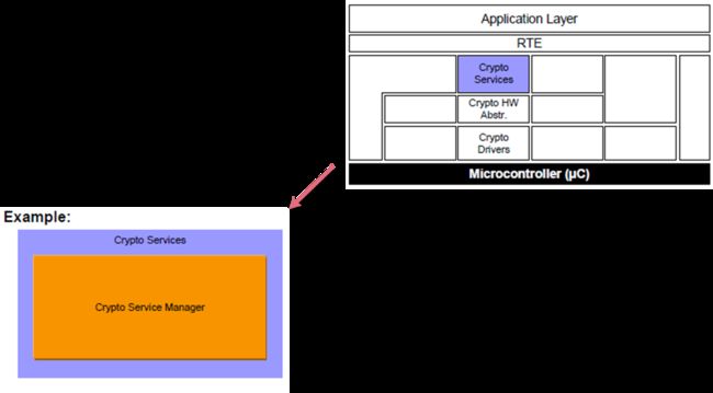
Crypto Services
加密服务由一个模块组成,即加密服务管理器。它负责加密作业的管理和密钥的存储。
任务:以统一的方式为应用程序提供加密原语和密钥存储。
摘要来自硬件设备和属性。
属性:
实现:μC和ECU硬件独立,高度可配置
上层接口:μC和ECU硬件独立,根据AUTOSAR指定和实现(AUTOSAR接口)
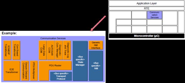
Communication Services
通信服务是一组用于车辆网络通信(CAN、LIN、FlexRay和以太网)的模块。它们通过通信硬件抽象与通信驱动程序接口。
任务:
为车辆网络提供统一的通信接口。
为网络管理提供统一服务。
为诊断通信提供统一的车辆网络接口
在应用程序中隐藏协议和消息属性。
属性:
实现:μC和ECU硬件独立,部分取决于总线类型
上层接口:μC、ECU硬件和总线类型独立
每个相关车辆网络系统的通信服务将在以下页面上详细说明。
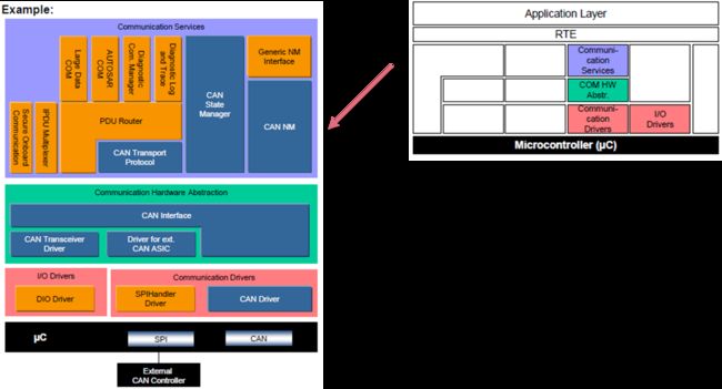
CAN Communication Stack
CAN通信堆栈是一组模块,用于与通信系统CAN进行车辆网络通信。
为CAN网络提供统一的接口。在应用程序中隐藏协议和消息属性。
CAN2.0版本
CANFD
实现:μC和ECU硬件独立,部分依赖CAN。
- AUTOSAR COM、通用NM(网络管理)接口和诊断通信管理器适用于所有车辆网络系统,并作为每个ECU的一个实例存在。
- 通用NM接口仅包含一个调度器。不包括其他功能。在网关ECU的情况下,它还可以包括NM协调器功能,该功能允许同步多个不同的网络(相同或不同类型)以同步唤醒或关闭它们。
- CAN NM特定于CAN网络,并将根据CAN车辆网络系统进行实例化。
- 通信系统特定的Can State Manager处理与通信系统相关的启动和关闭功能。此外,它控制COM的不同选项来发送PDU和监视信号超时。
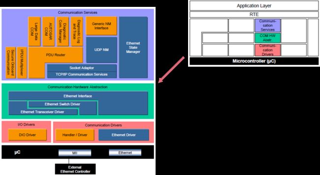
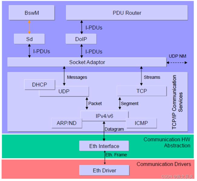
TCP/IP Communication stack
TCP/IP通信堆栈是用于与通信系统TCP/IP进行车辆网络通信的一组模块。
为TCP/IP网络提供统一的接口。在应用程序中隐藏协议和消息属性。
TcpIp模块实现TCP/IP协议家族的主要协议(TCP、UDP、IPv4、IPv6、ARP、ICMP、DHCP),并通过以太网提供基于套接字的动态通信。
套接字适配器模块(SoAd)是TcpIp模块中唯一的上层模块。
Memory Services
内存服务由一个模块组成,即NVRAM管理器。它负责管理非易失性数据(从不同的内存驱动程序读取/写入)。
- 以统一的方式向应用程序提供非易失性数据
- 内存位置和属性摘要
- 提供非易失性数据管理机制
以统一的方式向应用程序提供非易失性数据。从内存位置和属性中提取。提供非易失性数据管理机制,如保存、加载、校验和保护和验证、可靠存储等。
属性:
实现:μC和ECU硬件独立,高度可配置
上层接口:μC和ECU硬件独立,根据AUTOSAR指定和实现(AUTOSAR接口)
System Services
系统服务是一组模块和功能,可供所有层的模块使用。例如实时操作系统(包括定时器服务)和错误管理器。
- μC相关(如操作系统),并支持特殊的μC功能(如时间服务),
- 部分依赖于ECU硬件和应用程序(如ECU状态管理器)或独立于硬件和μC。
为应用程序和基本软件模块提供基本服务。
属性:
实现:部分μC、ECU硬件和特定应用
上层接口:μC和ECU硬件独立
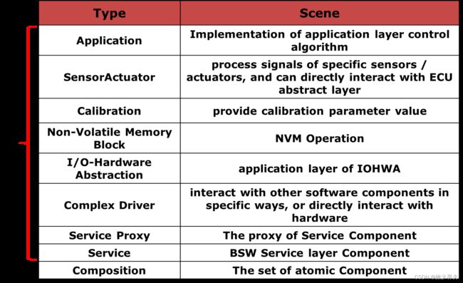
SWC Component Type
Atomic Software Components (SWC)
Atomic SWC是可以映射到ECU的最小软件单元。
SWC可以通过组件连接进行连接
端口定义了通信需求
接口和数据类型定义了通信的内容
端口可以通过部件连接器连接
Composition Software Components (CSWC)
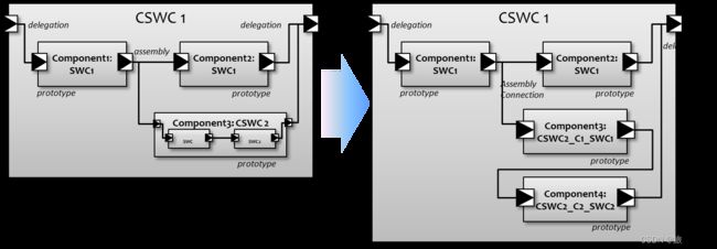
合成SWC是原子SWC和合成SWC的逻辑合成。
组成部分边界上的港口称为外港
组合内部的端口称为内部端口
委派连接连接内部和外部端口
端口必须是“已提供”或“必需”的相同类型
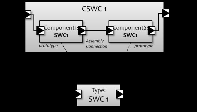
SWC Type and Prototype
SWC类型就像一个可重复使用的软件单元
原型代表SWC类型的实例
- 例如,组合包含参考SWC类型的组件原型
- 例如两个原型(组件1和组件2是同一软件组件类型SWC1的实例)
Flattening Compositions
组合物可以包含原子和/或复合SWC的原型(实例)
为了避免以后的名称冲突,必须取消组合
平面合成仅包含ATOMIC组件
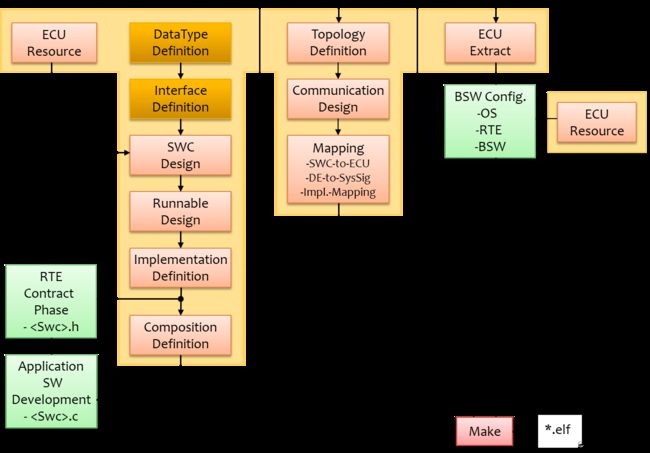
SWC Design - Flow
SWC Design - DataType
“数据类型创建” 流程
SWC Design - DataType
实施数据类型:
| Type |
Scene |
Sample |
| Value |
Define a datatype of base type, can add compu method 、data constraint、invalid value |
typedef unsigned long uint32; |
| Type Reference |
A type reference expresses a redirection to another data type,not need to choose base type |
typedef MySimpleType MyTypeRef; |
| Data Reference |
A data reference expresses a pointer type as defined by the C code statement |
typedef MySimpleType * MyDataRef; or typedef void * MyDataRef;. |
| Union |
Only one of the union elements might hold data at a given time |
typedef union{ uint32 UnionElement0; } MyUnitCode; |
| Array |
The element type of the can be Value, Type Reference, Array or Record and a fixed or variable size |
typedef uint64 MyArrayCode[5]; |
| Record |
define a struct type |
typedef struct{ uint16 RecordElement; CounterType RecordElement_1; } MyRecordCode; |
SWC Design - Interface
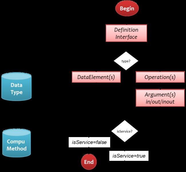
“接口创建”流程
Sender/Receiver Communication
1..m Multiplicity (Multicast)
n..1 Multiplicity
Transfer of Data element
of a certain Data type (e.g. Uint8)
Data Elements are Variables:Base Type、record
Client/Server Communication
n..1 Multiplicity
Sync or async
Transfer of Arguments to/from an Operation
Arguments are Variables
Arguments have a direction “in, out, inout”
Return of ErrorCodes possible using “ApplicationError”
SWC Design – Create Component
Define Atomic Component Sample :
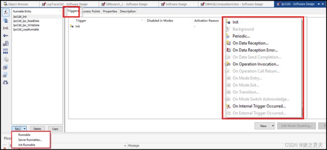
SWC Design – Runnable Design
The runnable entity is triggered exactly once on start up of the component.
Runnables with init triggers are not allowed to have other triggers.
The runnable entity is periodically triggered.
SWC Design – Runnable Design
The runnable entity is triggered upon an incoming data element.
Can select data elements of all receiver port of the component type.
Used for unqueued communication.
The runnable entity is triggered upon an incoming data element.
Can select data elements of all receiver port of the component type.
The runnable entity is triggered upon completion of sending an output data element (Tx Acknowledge).
Can select data elements of all sender port of the component type.
The runnable entity is triggered upon an incoming server call.
Can select data elements of all server port of the component type.
An operation invocation trigger may not be combined with any other kind of trigger. It may only be combined with triggers of other operations, provided that they have a compatible list of argument prototypes.
The runnable entity is triggered upon return of an asynchronous operation
call of a client port prototype.
Can select data elements of all client port of the component type.
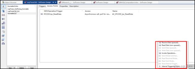
The runnable entity may receive data from a receiver port prototype.
This kind of port access is only available for queued data element prototypes.
The runnable entity may read data from a receiver port prototype.
This kind of port access is only available for unqueued data element prototypes
The runnable entity may send data to a sender port prototype.
This kind of port access is only available for queued data element prototypes.
The runnable entity may write data to a sender port prototype.
This kind of port access is only available for unqueued data element prototypes
The runnable entity may invoke operations of a client port prototype
AutoSAR Interface
| Type |
Scene |
| AUTOSAR Interface |
An "AUTOSAR Interface" defines the information exchanged between software components and/or BSW modules. This description is independent of a specific programming language, ECU or network technology. AUTOSAR Interfaces are used in defining the ports of software-components and/or BSW modules. Through these ports software-components and/or BSW modules can communicate with each other (send or receive information or invoke services). AUTOSAR makes it possible to implement this communication between Software-Components and/or BSW modules either locally or via a network. |
| Standardized AUTOSAR Interface |
A "Standardized AUTOSAR Interface" is an "AUTOSAR Interface" whose syntax and semantics are standardized in AUTOSAR. The "Standardized AUTOSAR Interfaces" are typically used to define AUTOSAR Services, which are standardized services provided by the AUTOSAR Basic Software to the application Software-Components. |
| Standardized Interface |
A "Standardized Interface" is an API which is standardized within AUTOSAR without using the "AUTOSAR Interface" technique. These "Standardized Interfaces" are typically defined for a specific programming language (like "C"). Because of this, "standardized interfaces" are typically used between software-modules which are always on the same ECU. When software modules communicate through a "standardized interface", it is NOT possible any more to route the communication between the software-modules through a network. |
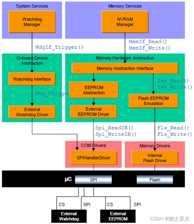
This example shows how the NVRAM Manager and the Watchdog Manager interact with drivers on an assumed hardware configuration
The ECU hardware includes an external EEPROM and an external watchdog connected to the microcontroller via the same SPI.
The SPIHandlerDriver controls the concurrent access to the SPI hardware and has to give the watchdog access a higher priority than the EEPROM access.
The microcontroller includes also an internal flash which is used in parallel to the external EEPROM. The EEPROM Abstraction and the Flash EEPROM Emulation have an API that is semantically identical.
The Memory Abstraction Interface can be realized in the following ways:
routing during runtime based on device index (int/ext)
routing during runtime based on the block index (e.g. > 0x01FF = external EEPROM)
routing during configuration time via ROM tables with function pointers inside the NVRAM Manager (in this case the Memory Abstraction Interface only exists „virtually“)
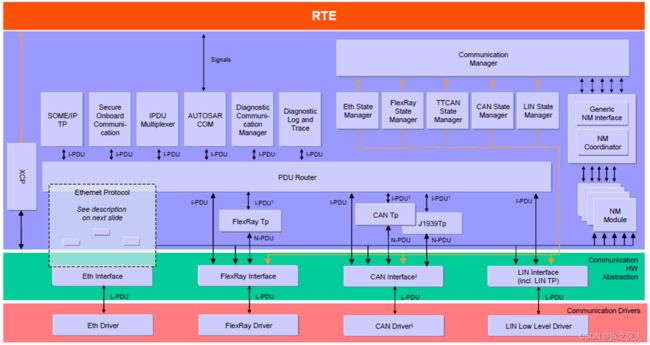
This example shows the Example “Communication”
PDU Router:
- Provides routing of PDUs between different abstract communication controllers and upper layers
- Scale of the Router is ECU specific (down to no size if e.g. only one communication controller exists)
- Provides TP routing on-the-fly. Transfer of TP data is started before full TP data is buffered
COM:
- Provides routing of individual signals or groups of signals between different I-PDUs
NM Coordinator:
- Synchronization of Network States of different communication channels connected to an ECU via the network managements handled by the NM Coordinator
Communication State Managers:
- Start and Shutdown the hardware units of the communication systems via the interfaces
- Control PDU groups
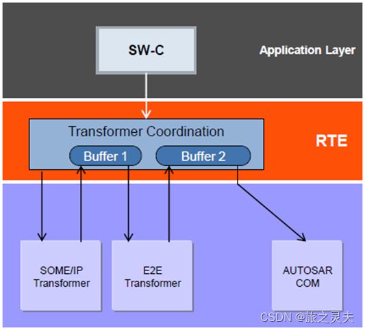
This example shows the data flow if data transformation is used for inter-ECU communication. A SW-C sends data configured to be transmitted to a remote ECU and subject to data transformation. This data transformation doesn’t use in-place buffer handling.
- The RTE calls the SOME/IP transformer as the first transformer in the chain and transfers the data from the SW-C.
- The SOME/IP transformer executes the transformation and writes the output (byte array) to a buffer provided by the RTE.
- The RTE executes the Safety transformer which is second in the transformer chain. The Safety transformer’s input is the output of the SOME/IP transformer.
- The Safety transformer protects the data and writes the output into another buffer provided by the RTE. A new buffer is required because in-place buffer handling is not used.
- The RTE transfers the final output data as a byte array to the COM module.
