多路选择器设计实现
文章目录
- 一、多路选择器
- 二、二选一多路选择器
- 三、四选一多路选择器设计
一、多路选择器
多路选择器是数据选择器的别称。在多路数据传送过程中,能够根据需要将其中任意一路选出来的电路,叫做数据选择器,也称多路选择器或多路开关。
二、二选一多路选择器
二选一多路选择器有两个输入数据,分别为in_a和in_b。为了确定选择那一路数据通过,还有一个选择段sel。
预想设计如下:
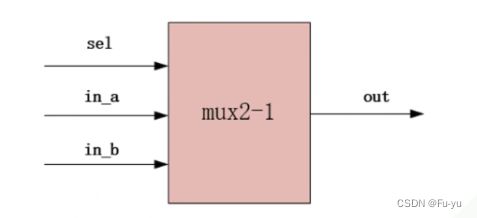
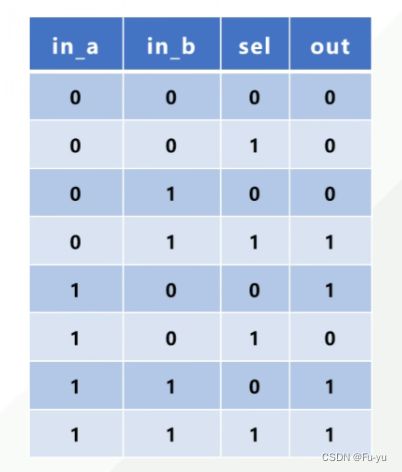
二选一多路选择器设计,sel为0时out输出in_a的值,sel为1时out输出in_b的值。
使用verilog代码设计如下:
第一种设计方案,使用assing赋值,三目元算符的方法:
/*
2023.7.20
二选一多路选择器设计,sel为0时out输出in_a的值,sel为1时out输出in_b的值
*/
module MUX_2_1 (
    input       wire        in_a    ,
    input       wire        in_b    ,
    input       wire        sel     ,

    output      wire        out
);

//使用assign方法直接赋值,三目运算符
assign out = sel ? in_b : in_a;


endmodule //MUX_2_1
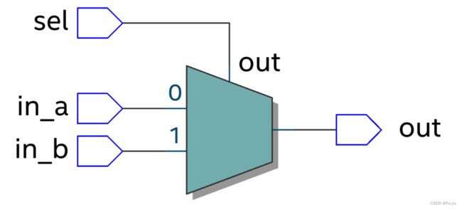
使用此方法所设计的电路图如下:
第二种方案使用always语句块,if-else的方法设计:
/*
2023.7.20
二选一多路选择器设计,sel为0时out输出in_a的值,sel为1时out输出in_b的值
*/
module MUX_2_1 (
    input       wire        in_a    ,
    input       wire        in_b    ,
    input       wire        sel     ,

    output      wire        out
);

reg out_r;

// //使用always模块进行赋值
//if-else
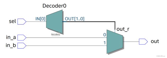
always @(*) begin
    if(sel) begin
         out_r = in_b;
    end
     else begin
         out_r = in_a;
     end
 end
  assign out = out_r;

endmodule //MUX_2_1
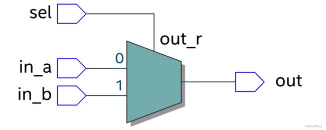
使用此方法所设计的电路图如下:
第三种设计方案,使用always语句块,case的方法设计:
/*
2023.7.20
二选一多路选择器设计,sel为0时out输出in_a的值,sel为1时out输出in_b的值
*/
module MUX_2_1 (
    input       wire        in_a    ,
    input       wire        in_b    ,
    input       wire        sel     ,

    output      wire        out
);

reg out_r;
//case语句
always @( *) begin
    case(sel)
        0 : begin
            out_r = in_a;
        end
        1 : begin
            out_r = in_b;
        end
        default :;
    endcase
end
assign out = out_r;

endmodule //MUX_2_1
使用此方法所设计的电路图如下:
测试验证
为验证所设计二选一多路选择器设计是否正确,我们通过编写测试仿真代码来验证:
`timescale 1ns/1ns
module MUX_2_1_tb();
    //激励信号定义
    reg tb_in_a;
    reg tb_in_b;
    reg tb_sel;

    //输出信号定义
    wire tb_out;


//模拟输入
    initial begin
        tb_in_a = 0;
        tb_in_b = 0;
        tb_sel = 0;
        #1;
        tb_in_a = 0;
        tb_in_b = 0;
        tb_sel = 1;
        #1;
        tb_in_a = 1;
        tb_in_b = 0;
        tb_sel = 0;
        #1;
        tb_in_a = 1;
        tb_in_b = 0;
        tb_sel = 1;
        #1;
        tb_in_a = 0;
        tb_in_b = 1;
        tb_sel = 0;
        #1;
        tb_in_a = 0;
        tb_in_b = 1;
        tb_sel = 1;
        #1;
        tb_in_a = 1;
        tb_in_b = 1;
        tb_sel = 0;
        #1;
        tb_in_a = 1;
        tb_in_b = 1;
        tb_sel = 1;
        #1;
    end

//模块例化
 MUX_2_1  u_MUX_2_1(
    .in_a    (tb_in_a)    ,
    .in_b    (tb_in_b)    ,
    .sel     (tb_sel)     ,

    .out     (tb_out)
);


endmodule
通过观察仿真时序图可以发现,当sel信号为0时,out的输出值与in_a的值相同,当sel信号为1时,out的输出值与in_b的值相同,和我们预期所相符合。

三、四选一多路选择器设计
在刚才所做的二选一的多路选择器的基础上,设计一个新的四选一的多路选择器。
代码设计如下:
/*
2023.7.10
四选一多路选择器设计
*/

module MUX_4_1 (
    input   wire [3:0]      in_a,//4位的输入
    input   wire [1:0]      sel,//sel选择in_a哪一位的输出

    output  reg             out

);

always @( *) begin
    case (sel)
        0 : begin
            out = in_a[0];
        end
        1 : begin
            out = in_a[1];
        end
        2 : begin
            out = in_a[2];
        end
        3 : begin
            out = in_a[3];
        end
        default :;
    endcase
end

endmodule //MUX_4_1
测试文件:
`timescale 1ns/1ns

module MUX_4_1_tb();
//输入信号
reg [3:0] tb_in_a;
reg [1:0] tb_seg;
//输出信号
wire tb_out;

//模块实例化
MUX_4_1 u_MUX_4_1(
   .     in_a  (tb_in_a)  ,
   .     sel   (tb_seg)  ,

   .     out    (tb_out)

);

initial begin
    tb_in_a = 4'b0001;//输出1
    tb_seg = 0;
    #1;
    tb_in_a = 4'b1000;//输出0
    tb_seg = 0;
    #1;
    tb_in_a = 4'b0100;//输出0
    tb_seg = 0;
    #1;
    tb_in_a = 4'b1001;//输出0
    tb_seg = 1;
    #1;
    tb_in_a = 4'b1110;//输出1
    tb_seg = 1;
    #1;
    tb_in_a = 4'b0010;//输出1
    tb_seg = 1;
    #1;
    tb_in_a = 4'b0011;//输出0
    tb_seg = 2;
    #1;
    tb_in_a = 4'b0100;//输出1
    tb_seg = 2;
    #1;
    tb_in_a = 4'b1011;//输出1
    tb_seg = 3;
    #1;
    tb_in_a = 4'b0111;//输出0
    tb_seg = 3;
    #1;
    tb_in_a = 4'b1100;//输出1
    tb_seg = 3;
    #1;
end


endmodule
通过仿真,观察波形图:
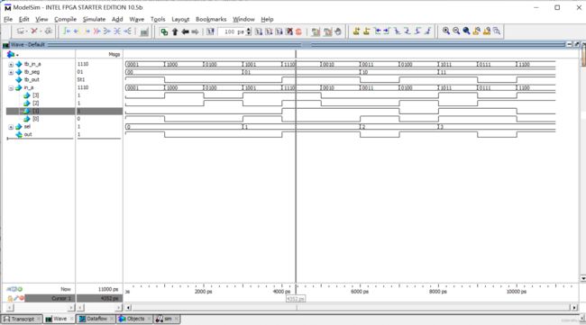
从图中可以观察到,当sel信号为0时,out的输出值与in_a[0]的值相同;当sel信号为1时,out的输出值与in_a[1]的值相同;当sel信号为2时,out的输出值与in_a[2]的值相同;当sel信号为3时,out的输出值与in_a[3]的值相同。