数字保险箱(RP2040+W5100S+指纹)第1部分
数字保险箱(RP2040+W5100S+指纹)第1部分:软件
转发: Digital Safe Box (RP2040+W5100S+FingerPrint) Part 1
项目介绍
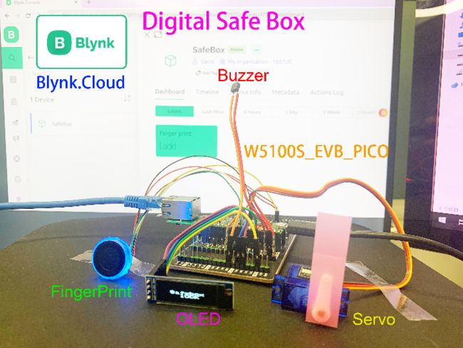
我想用树莓派的RP2040做一个数字保险箱,有指纹识别和12个键(0~9、*、#)的触摸键盘。 并通过伺服来解锁和锁定,并通过以太网(W5100s)将锁定开关信息传输到IOT平台,再加上OLED屏幕来显示设备状态,以及蜂鸣器来警告异常情况。
通过上面的描述,这个项目中用到了很多外设
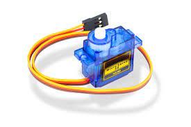
※ 舵机 (SG90)
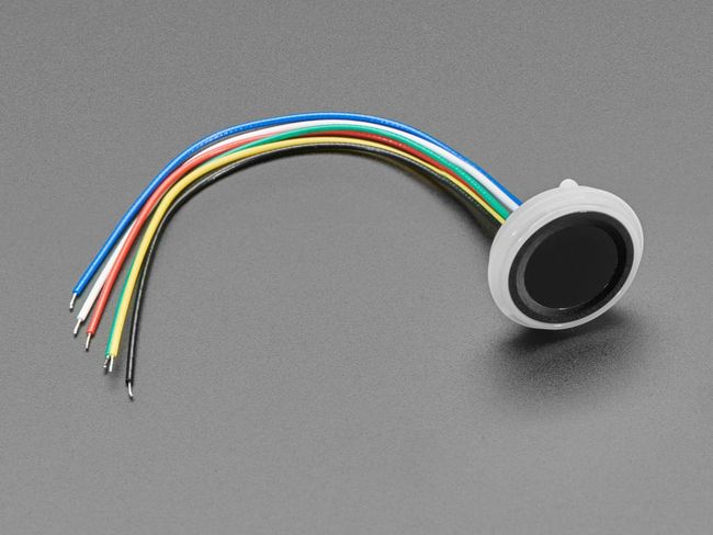
※指纹模块
这是我很久以前买的一个模块。 该型号可以存储50组指纹,但最新型号可以存储和识别300组指纹。
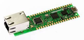
※ 以太网W5100S
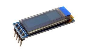
※ SSD1306 OLED模组
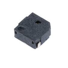
※ 蜂鸣器
※ 触摸键键盘
etc.
所以在开始PCB设计之前我做了很多测试工作,对每个模块都进行了单独的测试,除了触摸按键键盘部分,因为我想用RP2040的引脚直接支持触摸按键,而不是通过TTP224。 我没有找到可以直接触摸的测试板,所以这部分只有在我的PCB硬件从工厂带回来后才进行测试。
这次我还是想通过ChatGpt来生成我的代码,至少是辅助生成。
Q:
我想用Raspberry Pi RP2040开发一个迷你保险箱,基于Arduino,带有W5100S以太网芯片,键盘有12个触摸按钮,分别是0~9和*,#。 OLED屏幕显示状态和指纹识别。 我怎么能够?
ChatGPT:
使用您提到的组件开发迷你保险箱是一个有趣的项目! 它涉及硬件集成、编程和一些电子知识。 以下是帮助您入门的一般路线图:
收集组件:确保您拥有所有必需的组件:Raspberry Pi RP2040、W5100S 以太网芯片、触摸按钮、OLED 屏幕、指纹传感器、电线、电源等。
设置 Raspberry Pi RP2040:通过设置必要的软件来准备 RP2040。 您需要一张 microSD 卡,上面刷入了合适的操作系统(例如 Raspberry Pi OS Lite)。 按照官方文档进行设置。
连接组件:根据数据表和引脚配置连接所有组件。 例如:
将W5100S以太网芯片连接到RP2040的SPI引脚。
使用 I2C 引脚连接 OLED 屏幕。
将触摸按钮连接到 RP2040 的 GPIO 引脚。
根据指纹传感器的数据表连接指纹传感器。
连接组件:根据数据表和引脚配置连接所有组件。 例如:将W5100S以太网芯片连接到RP2040的SPI引脚。 使用 I2C 引脚连接 OLED 屏幕。 将触摸按钮连接到 RP2040 的 GPIO 引脚。 根据指纹传感器的数据表连接指纹传感器。
安装所需的库:根据您使用的组件,您可能需要安装库才能与它们通信。 这些库将提供允许您有效地与设备交互的功能。 例如:
安装以太网芯片(W5100S)的库以启用网络通信。
安装 OLED 屏幕的库以显示状态信息。
安装指纹传感器库以捕获和识别指纹。
安装所需的库:根据您使用的组件,您可能需要安装库才能与它们通信。 这些库将提供允许您有效地与设备交互的功能。 例如:安装以太网芯片(W5100S)的库,实现网络通信。 安装 OLED 屏幕的库以显示状态信息。 安装指纹传感器库以捕获和识别指纹。
编写代码:这是您的大部分工作所在。 您需要编写代码:
初始化并管理以太网连接以允许远程访问。
与OLED屏幕接口,显示相关信息。
处理触摸按钮的输入以检测按钮按下情况。
与指纹传感器通信以登记和验证指纹。
编写代码:这是您的大部分工作所在。 您需要编写代码来: 初始化和管理以太网连接以允许远程访问。 与OLED屏幕接口,显示相关信息。 处理触摸按钮的输入以检测按钮按下情况。 与指纹传感器通信以登记和验证指纹。
集成和逻辑:这是将所有内容整合在一起的地方。 实现保险箱的逻辑,例如:
在授予访问权限之前需要有效的指纹。
需要通过触摸按钮输入正确的 PIN 码。
在 OLED 屏幕上显示不同的状态(锁定、解锁、错误消息等)。
根据有效输入控制锁定和解锁机制。
集成和逻辑:这是将所有内容整合在一起的地方。 实现保险箱的逻辑,例如:在授予访问权限之前需要有效的指纹。 需要通过触摸按钮输入正确的 PIN 码。 在 OLED 屏幕上显示不同的状态(锁定、解锁、错误消息等)。 根据有效输入控制锁定和解锁机制。
测试和调试:彻底测试您的设置。 使用调试工具、打印语句和其他方法来识别和修复测试过程中出现的任何问题。
测试和调试:彻底测试您的设置。 使用调试工具、打印语句和其他方法来识别和修复测试过程中出现的任何问题。
外壳和最终确定:为您的迷你保险箱设计并建造合适的外壳。 确保为组件(OLED 屏幕、指纹传感器、触摸按钮等)提供适当的开口。 外壳应保护组件并为您的项目提供精美的外观。
外壳和最终确定:为您的迷你保险箱设计并建造合适的外壳。 确保为组件(OLED 屏幕、指纹传感器、触摸按钮等)提供适当的开口。 外壳应保护组件并为您的项目提供精美的外观。
安全注意事项:由于这是一个保险箱,因此安全性至关重要。 确保为远程访问、指纹存储和 PIN 输入实施正确的加密和身份验证机制。
安全注意事项:由于这是一个保险箱,因此安全性至关重要。 确保为远程访问、指纹存储和 PIN 输入实施正确的加密和身份验证机制。
用户手册:编写用户手册,解释如何使用保险箱、登记指纹、设置 PIN 码以及解决常见问题。
用户手册:编写用户手册,解释如何使用保险箱、登记指纹、设置 PIN 码以及解决常见问题。
请记住,该项目涉及多个组件和技术,因此请逐步进行。 这也是了解硬件集成、网络以及与各种设备连接的绝佳机会。 祝您的迷你保险箱项目好运!
Q:
我使用的是arduino,指纹模块连接到软串口,使用的TX引脚是GPIO26,RX引脚是GPIO27。 舵机使用GPIO21,那么请给我一个参考代码。
ChatGPT:
当然,这里有一个参考代码大纲,可帮助您使用您提到的组件开始基于 Arduino 的迷你保险箱项目。 请注意,这是一个简化的示例,您可能需要根据您的特定硬件、库和要求对其进行修改和扩展。
#include
#include
#include
#include

// Pin definitions
#define FINGERPRINT_RX_PIN 26
#define FINGERPRINT_TX_PIN 27
#define OLED_RESET -1
#define OLED_SDA 4
#define OLED_SCL 5
#define SERVO_PIN 21

// Initialize components
SoftwareSerial fingerprintSerial(FINGERPRINT_RX_PIN, FINGERPRINT_TX_PIN);
Adafruit_SSD1306 display(OLED_RESET);
Servo servo;

void setup() {
  // Initialize components
  Serial.begin(9600);
  fingerprintSerial.begin(57600);
  display.begin(SSD1306_I2C_ADDRESS, OLED_SDA, OLED_SCL);
  servo.attach(SERVO_PIN);

  // Display initialization message
  display.clearDisplay();
  display.setTextSize(1);
  display.setTextColor(SSD1306_WHITE);
  display.setCursor(0, 0);
  display.println("Mini Safebox");
  display.display();
  delay(2000);

  // Initialize servo position
  servo.write(0); // Locked position
}

void loop() {
  // Your main logic here

  // Check for fingerprint input
  if (fingerprintSerial.available()) {
    // Read fingerprint data and process
    // Add your fingerprint recognition logic here
    // Example: if (recognizedFingerprint) { unlockSafebox(); }
  }

  // Check for touch button input
  // Add your touch button logic here

  // Display status on OLED
  // Add OLED display logic here
}

void unlockSafebox() {
  servo.write(90); // Unlock the safebox
  delay(2000);     // Keep it unlocked for 2 seconds
  servo.write(0);  // Lock the safebox again
}
请注意,此代码只是一个起点,可能需要根据您正在使用的特定库、您想要实现的行为以及您正在使用的指纹识别库进行修改(因为指纹模块的 API 可能有所不同)。
另外,请记住,在处理保险箱时,安全性是一个关键方面。 确保实施安全的指纹存储和身份验证机制。 处理敏感数据时使用适当的加密技术。
当您完成该项目时,请参阅您正在使用的库的文档和组件的数据表,以获取有关其用法的更多详细信息。
----------------------------------------------
Q:
我的测试基于W5100S_EVB_PICO板,请添加以太网部分,我想在指纹识别后将识别到的指纹ID号发送到物联网平台BLYNK,请帮助我。
ChatGPT:
当然,这是一个完整的集成代码示例,结合了指纹识别、OLED 显示、以太网通信和 Blynk 集成:
#include
#include
#include
#include
#include
#include
#include

// Pin definitions
#define FINGERPRINT_RX_PIN 23
#define FINGERPRINT_TX_PIN 24
#define OLED_RESET -1
#define OLED_SDA 4
#define OLED_SCL 5
#define SERVO_PIN 6

// Initialize components
SoftwareSerial fingerprintSerial(FINGERPRINT_RX_PIN, FINGERPRINT_TX_PIN);
Adafruit_SSD1306 display(OLED_RESET);
Servo servo;

byte mac[] = { 0xDE, 0xAD, 0xBE, 0xEF, 0xFE, 0xED };  // MAC address of your Ethernet shield
IPAddress ip(192, 168, 1, 100);  // IP address of your Arduino
IPAddress server(192, 168, 1, 2); // IP address of your Blynk server
char auth[] = "YOUR_BLYNK_AUTH_TOKEN";

void setup() {
  // Initialize components
  Serial.begin(9600);
  fingerprintSerial.begin(57600);
  display.begin(SSD1306_SWITCHCAPVCC, 0x3C);
  servo.attach(SERVO_PIN);

  setupEthernet();
  setupBlynk();

  display.clearDisplay();
  display.setTextSize(1);
  display.setTextColor(SSD1306_WHITE);
  display.setCursor(0, 0);
  display.println("Mini Safebox");
  display.display();
  delay(2000);

  servo.write(0); // Locked position
}

void loop() {
  Blynk.run(); // Blynk communication

  // Your main logic here

  // Check for fingerprint input
  if (fingerprintSerial.available()) {
    int recognizedFingerprintID = readFingerprint(); // Replace with your fingerprint recognition logic
    if (recognizedFingerprintID != -1) {
      sendFingerprintToBlynk(recognizedFingerprintID);
    }
  }

  // Other logic and communication here

  // Display status on OLED
  // Add OLED display logic here
}

void setupEthernet() {
  Ethernet.begin(mac, ip);
}

void setupBlynk() {
  Blynk.begin(auth, IPAddress(192, 168, 1, 2), 8080);
}

void sendFingerprintToBlynk(int fingerprintID) {
  Blynk.virtualWrite(V1, fingerprintID); // Assuming you're using Virtual Pin V1
}

int readFingerprint() {
  // Replace with your fingerprint recognition logic
  // Return recognized fingerprint ID or -1 if not recognized
} 请记住将“YOUR_BLYNK_AUTH_TOKEN”替换为您的实际 Blynk 身份验证令牌。 根据您的网络配置和 Blynk 项目调整 IP 地址、设置和虚拟 Pin。
该代码结合了您描述的各种组件和功能:指纹识别、OLED 显示屏、与 W5100S 的以太网通信以及 Blynk 集成。 需要注意的是,此代码是一个模板,您需要使用指纹模块的库或命令来实现实际的指纹识别逻辑。
另外,请确保您已通过 Arduino 库管理器安装了所需的库(SoftwareSerial、Adafruit_SSD1306、Servo、Ethernet2、BlynkSimpleEthernet2 等)。
拿到ChatGPT生成的参考代码后,我根据自己的经验做了一些修改,添加了一些内容。
/* Fill-in information from Blynk Device Info here */
#define BLYNK_TEMPLATE_ID           "*******"
#define BLYNK_TEMPLATE_NAME         "********"
#define BLYNK_AUTH_TOKEN            "**************************"

/* Comment this out to disable prints and save space */
#define  BLYNK_PRINT Serial

#include
#include
#include
#include
#include
#include
#include
#include

BlynkTimer timer;

#define FINGERPRINT_RX_PIN 27
#define FINGERPRINT_TX_PIN 26

SoftwareSerial fingerprintSerial(FINGERPRINT_RX_PIN, FINGERPRINT_TX_PIN); // Declare SoftwareSerial obj first
Adafruit_Fingerprint finger = Adafruit_Fingerprint(&fingerprintSerial);

#define SCREEN_WIDTH 128 // OLED display width, in pixels
#define SCREEN_HEIGHT 32 // OLED display height, in pixels
// Initialize components
#define OLED_RESET     -1 // Reset pin # (or -1 if sharing Arduino reset pin)
#define SCREEN_ADDRESS 0x3C ///< See datasheet for Address; 0x3D for 128x64, 0x3C for 128x32
Adafruit_SSD1306 display(SCREEN_WIDTH, SCREEN_HEIGHT, &Wire, OLED_RESET);

#define SERVO_PIN 22
Servo servo;

// Enter a MAC address and IP address for your controller below.
// The IP address will be dependent on your local network:
byte mac[] = {
  0xDE, 0xAD, 0xBE, 0xEF, 0xFE, 0xED
};
IPAddress ip(10, 0, 1, 226);

void setup() {

  servo.attach(SERVO_PIN);
  // Initialize servo position
  servo.write(360); // Locked position

  // Initialize components
  Serial.begin(9600);
  fingerprintSerial.begin(57600);
  display.begin(SSD1306_SWITCHCAPVCC, SCREEN_ADDRESS);

  // Display initialization message
  display.clearDisplay();
  display.setTextSize(2);
  display.setTextColor(SSD1306_WHITE);
  display.setCursor(24, 0);
  display.println("Safebox");
  display.setCursor(48, 16);
  display.println("Lock");
  display.display();
  delay(2000);

  Ethernet.init(17);  // WIZnet W5100S-EVB-Pico
  // start the Ethernet connection and the server:
  Ethernet.begin(mac, ip);
  // Check for Ethernet hardware present
  if (Ethernet.hardwareStatus() == EthernetNoHardware) {
    Serial.println("Ethernet shield was not found.  Sorry, can't run without hardware. :(");
    while (true) {
      delay(1); // do nothing, no point running without Ethernet hardware
    }
  }
  if (Ethernet.linkStatus() == LinkOFF) {
    Serial.println("Ethernet cable is not connected.");
  }

  Blynk.begin(BLYNK_AUTH_TOKEN);

  finger.getTemplateCount();

  if (finger.templateCount == 0) {
    Serial.print("Sensor doesn't contain any fingerprint data. Please run the 'enroll' example.");
  }
  else {
    Serial.println("Waiting for valid finger...");
      Serial.print("Sensor contains "); Serial.print(finger.templateCount); Serial.println(" templates");
  }
}

void loop() {

  Blynk.run();
  timer.run();

  getFingerprintID();
  delay(50);            //don't ned to run this at full speed.

  // Your main logic here

  // Check for fingerprint input
  if (fingerprintSerial.available()) {
    // Read fingerprint data and process
    // Add your fingerprint recognition logic here
    // Example: if (recognizedFingerprint) { unlockSafebox(); }
  }

  // Check for touch button input
  // Add your touch button logic here

  // Display status on OLED
  // Add OLED display logic here
}

uint8_t getFingerprintID() {
  uint8_t p = finger.getImage();
  switch (p) {
    case FINGERPRINT_OK:
      Serial.println("Image taken");
      break;
    case FINGERPRINT_NOFINGER:
      Serial.println("No finger detected");
      return p;
    case FINGERPRINT_PACKETRECIEVEERR:
      Serial.println("Communication error");
      return p;
    case FINGERPRINT_IMAGEFAIL:
      Serial.println("Imaging error");
      return p;
    default:
      Serial.println("Unknown error");
      return p;
  }

  // OK success!

  p = finger.image2Tz();
  switch (p) {
    case FINGERPRINT_OK:
      Serial.println("Image converted");
      break;
    case FINGERPRINT_IMAGEMESS:
      Serial.println("Image too messy");
      return p;
    case FINGERPRINT_PACKETRECIEVEERR:
      Serial.println("Communication error");
      return p;
    case FINGERPRINT_FEATUREFAIL:
      Serial.println("Could not find fingerprint features");
      return p;
    case FINGERPRINT_INVALIDIMAGE:
      Serial.println("Could not find fingerprint features");
      return p;
    default:
      Serial.println("Unknown error");
      return p;
  }

  // OK converted!
  p = finger.fingerSearch();
  if (p == FINGERPRINT_OK) {
    Serial.println("Found a print match!");
    unlockSafebox();
  } else if (p == FINGERPRINT_PACKETRECIEVEERR) {
    Serial.println("Communication error");
    return p;
  } else if (p == FINGERPRINT_NOTFOUND) {
    Serial.println("Did not find a match");

  // Display initialization message
  display.clearDisplay();
  display.setTextSize(2);
  display.setTextColor(SSD1306_WHITE);
  display.setCursor(24, 0);
  display.println("Safebox");
  display.setCursor(32, 16);
  display.println("ALARM");
  // Send it to the server
  Blynk.virtualWrite(V5, "ALARM!");
  display.display();

    for(int i=200;i<=800;i++)              //用循环的方式将频率从200HZ 增加到800HZ
    {
    pinMode(6,OUTPUT);
    tone(6,i);                             //在四号端口输出频率
    delay(5);                              //该频率维持5毫秒
    }
    delay(4000);
    noTone(6);

  // Display initialization message
  display.clearDisplay();
  display.setTextSize(2);
  display.setTextColor(SSD1306_WHITE);
  display.setCursor(24, 0);
  display.println("Safebox");
  display.setCursor(48, 16);
  display.println("lOCK");
  display.display();
  Blynk.virtualWrite(V5, "Lock!");
    return p;
  } else {
    Serial.println("Unknown error");
    return p;
  }

  // found a match!
  Serial.print("Found ID #"); Serial.print(finger.fingerID);
  Serial.print(" with confidence of "); Serial.println(finger.confidence);

  return finger.fingerID;
}

void unlockSafebox() {
  servo.write(180); // Unlock the safebox

  // Display initialization message
  display.clearDisplay();
  display.setTextSize(2);
  display.setTextColor(SSD1306_WHITE);
  display.setCursor(24, 0);
  display.println("Safebox");
  display.setCursor(32, 16);
  display.println("Unlock");
  display.display();

  // Send it to the server
  Blynk.virtualWrite(V5, String("Found a Finger ID:" + String(finger.fingerID)));

  delay(2000);     // Keep it unlocked for 2 seconds
  servo.write(360);  // Lock the safebox again

  // Display initialization message
  display.clearDisplay();
  display.setTextSize(2);
  display.setTextColor(SSD1306_WHITE);
  display.setCursor(24, 0);
  display.println("Safebox");
  display.setCursor(48, 16);
  display.println("Lock");
  display.display();
  delay(2000);
  // Send it to the server
  Blynk.virtualWrite(V5, "Lock!");
}
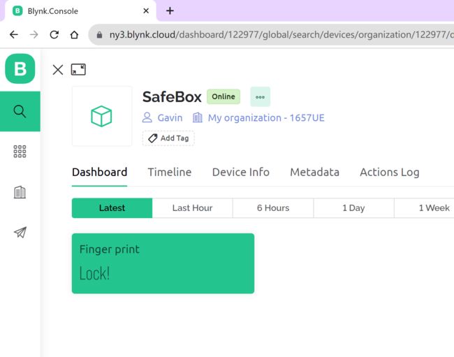
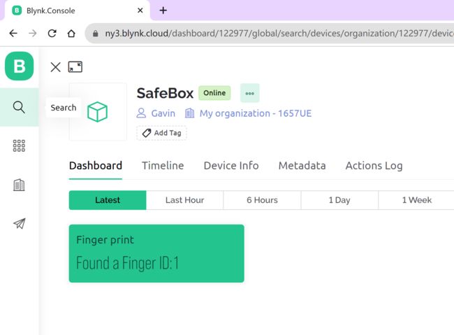
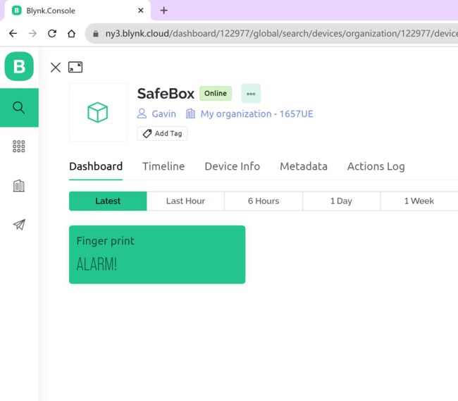
我连接BLYNK平台的想法是利用BLYNK的通知功能。 如果有人试图开锁,他们可以通过手机收到警告通知消息。 该功能还在调试中。
接收锁定消息:
接收发现消息:
RCV 警报消息:
基本代码和测试通过后,我就会开始PCB硬件设计和焊接工作,完成后分享给大家。
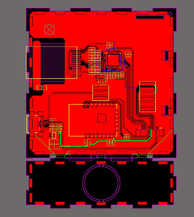
侧板:
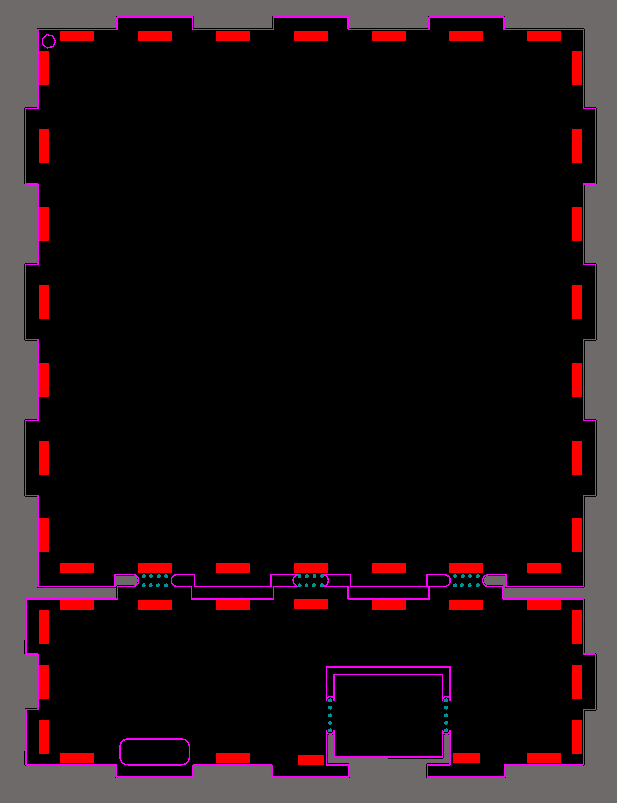
背板:
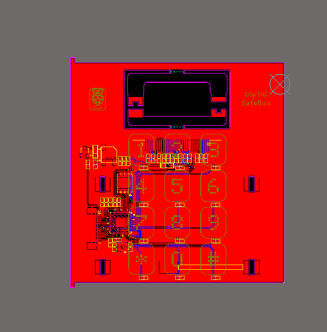
门板:
三块PCB通过三维结构组合在一起,成为保险柜的柜体。 预计下周硬件焊接即可完成,届时我会与大家分享进一步的进展。
