纸上谈兵_JESD204B
文章目录
- 基本概念
-
- 优点
- 子类
- 协议结构
-
- 链路参数
- 传输层
-
- 映射方式
- 测试模式
- 数据链路层
-
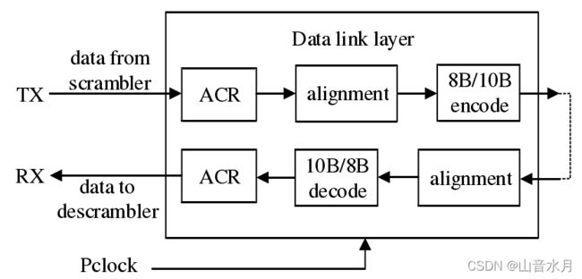
- 对齐字符替换与还原
- 数据链路建立与维护
- 物理层
- 时钟
-
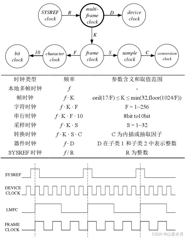
- 器件时钟
- 帧时钟/多帧时钟
- 调整时钟
- 各时钟关系图
- 各协议层时钟使用情况
- Xilinx IP
-
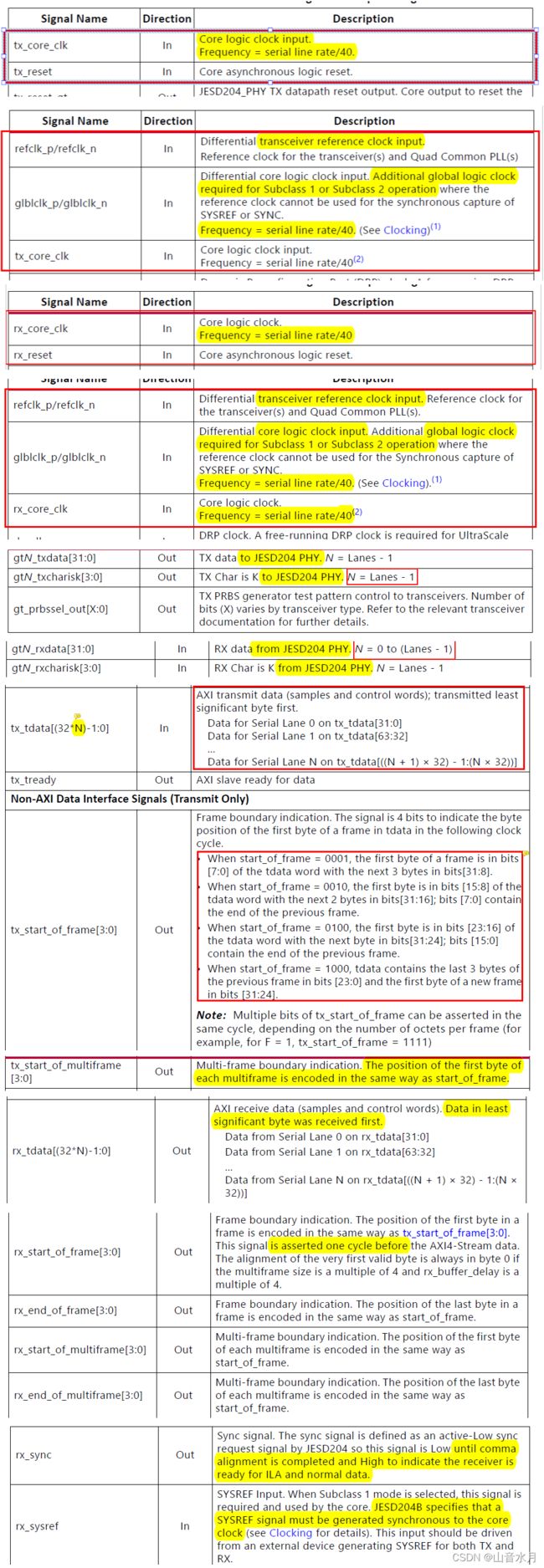
- Ports
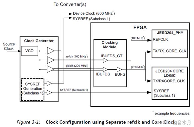
- Basic Generic Clocking Schemes
- Subclass 1 Operation
- Rx example仿真
-
- IP核设置
- 仿真
-
- 产生ILA序列
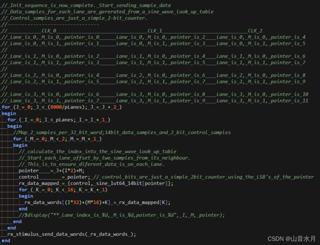
- 产生各个lane的数据;接收各个lane的数据
- 博文链接
基本概念
优点
JESD204B 协议的优点如下,
- 支持多通道、多链路和多芯片同步
- 支持确定性延迟
- 使用器件时钟(Device Clock)
- 单通道速率最高可达 12.5Gbps
确定性延迟的意义在于,当电路重新上电,或是重新进行同步时,这之间的延迟是确定的。
子类
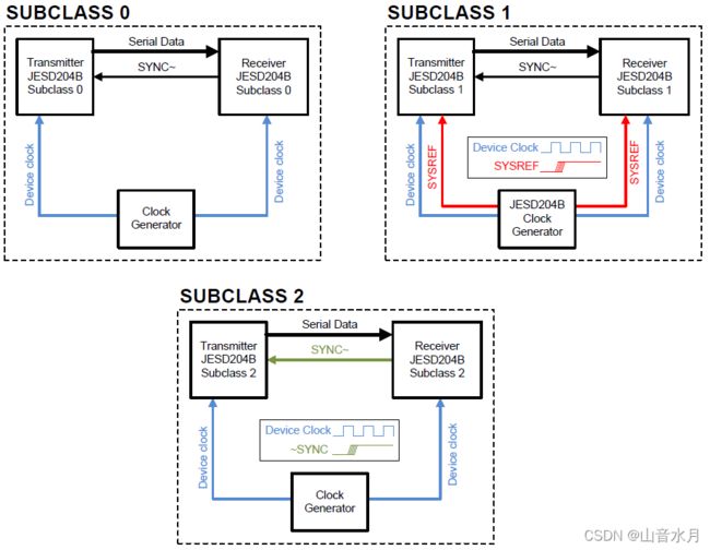
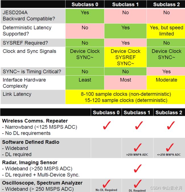
JESD204B 的子类说明如下,
| 子类 | 说明 |
|---|---|
| 子类 0 | 不支持确定性延时,向后兼容 JESD204A |
| 子类 1 | 使用 SYSREF参考时钟支持确定性延时 |
| 子类 2 | 使用 SYNC~时钟支持确定性延时 |
 |
|
 |
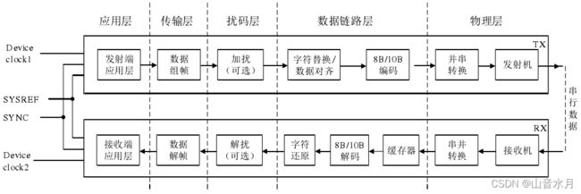
协议结构
链路参数
在使用时,需要针对特定应用场景所需的链路数、通道数、通道速率以及各时钟信号的频率,对链路参数进行配置。
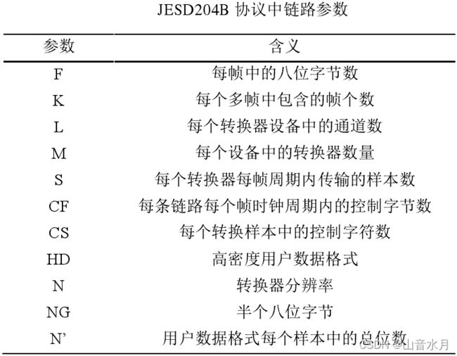
NP->ADC number of bits per sample
Understanding JESD204B Link Parameters
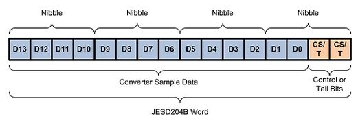
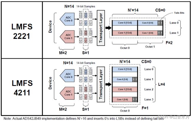
The N’ parameter is found by multiplying the number of nibbles by four. It can be advantageous to both the transmitter and receiver to set N’ to 16 for converters with resolutions ranging from eight bits to 16 bits. This allows for the same transmitter and receiver to be used for multiple converters, easing overall system design. A non-complete nibble has room for either control bits (CS ) or tail bits (T ) as defined by the JESD204B standard. The equation N’ = N + CS + T must be satisfied.For example, a 14-bit converter with N’ = 16 would have two bits left that could be used for control bits and/or tail bits. The figure below gives a visual representation of the how the converter data is mapped into a JESD204B word for a 14-bit converter with N’ = 16. If there are no tail bits or control bits, the JESD204B word is the same as the sample data. This would occur in this case if the resolution of the converter were equal to 16 bits instead of 14 bits. It is important to note that the left most bit is the most significant bit of the converter sample. Samples are transmitted across the link MSB first and LSB last. Control bits, if any, are appended after the LSB to each conversion sample.
The S parameter is the number of transmitted samples per converter per frame. Typically, the S parameter is set to one. This parameter must always be an integer to minimize cross talk between the JESD204B circuitry and the analog circuitry of the converter. The JESD204B specification allows for this parameter to be greater than one, but it is simpler to set S to one such that the frame clock (FC ) and sample clock of the converter can be equal. For a 500MSPS converter and S = 1, the frame clock rate is 500MHz.
The next parameter to set is the number of lanes, L . In order to determine the number of lanes required, the maximum lane rate must be known. The maximum lane rate is determined by two main factors: the output driver capability of the transmitter and the input capability of the receiver. To calculate the lane line rate and determine the number of lanes, Equation 1 is used:
Lane Rate = (M x S x N’ x 10/8 x FC)/L
Using the example information above with a quad-channel, 500MSPS 14-bit converter with N’ = 16 and S = 1, we can set the L parameter to different values and find the resultant lane rate to make sure it falls within system limitations. In this case, let’s assume the maximum lane rate that can be supported by the transmitter and receiver is equal to the maximum lane rate defined for the JESD204B specification, which is 12.5Gbit/s. If L = 2, the resultant lane rate is (4 x 1 x 16 x 10/8 x 500MHz)/2 = 20Gbit/s. This exceeds the accepted maximum. Clearly, L must be set to 4 in order to reduce the lane rate below the accepted maximum. With L = 4, the lane rate is 10Gbit/s, which complies with the maximum rate of 12.5Gbit/s.
After using the number of converters, the number of samples per frame, the JESD204B word size, and the maximum lane rate to calculate the number of lanes, we can determine the number of octets transmitted per frame, F . In order to determine this parameter, Equation 2 can be used:
F = (M x S x N’)/(8 x L)
Continuing with the information from the previous examples, F can be calculated. Substituting the values, we have F = (4 x 1 x 16)/(8 x 4) = 2. So for a quad-channel, 500MSPS 14-bit converter with four JESD204B lanes, there are two octets needed to transmit one sample of data per frame, which results in a lane rate of 10Gbit/s.
假设一个4通道的AD芯片,分辨率是14位,则M=4,N=14。在JESD204B的标准中要求,采样的一个数据必须要分解成半字节(nibble,4bit),那么14位的AD数据,能分解成3个nibble,还余下2位。那么余下的这2位,要与控制位(CS)或尾位(T)组成一个新的nibble。所以14位采样率的AD,需要4个nibble,那么N’=16,发送时先发送高位,再发送低位。同理,如果12位的AD,只需要3个nibble,不需要控制位或尾位在补充。
还是以一个4通道,500MSPS采样率,14位的AD为例,可以知道N’=16,S=1。假设器件支持的JESD204B协议的速率为12.5Gb/s,那么可以求得L=4的时候,速率为10Gb/s,这样才不会超过速率的最大限制;同样的,计算得出F=2,即每一帧传输中有2个字节的数据。
传输层
映射方式
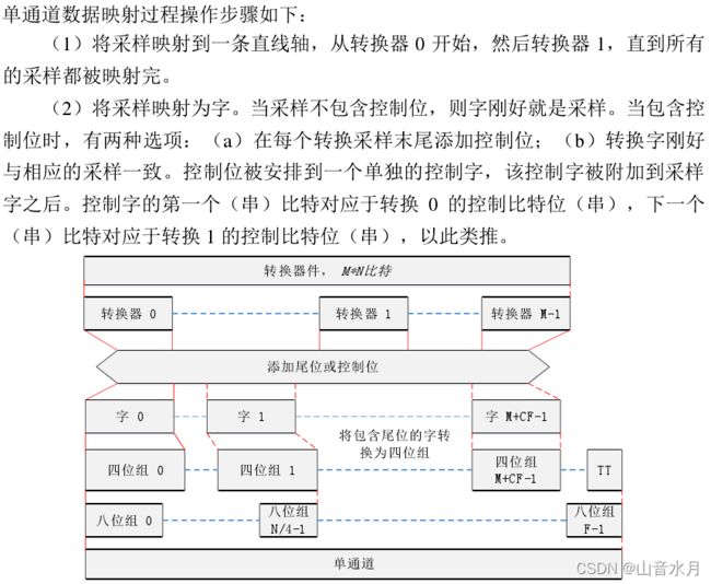
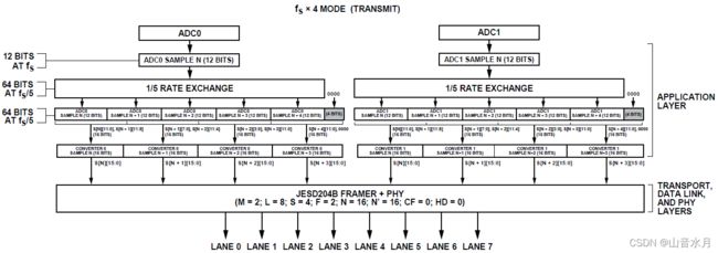
传输层按照应用层中的相关配置对对样本数据进行处理,将其映射为符合要求的帧数据。 协议定义了四种映射机制,如下所示,
- 单个转换器输出的样本映射到单通道中
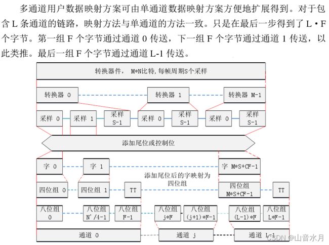
- 单个转换器输出的样本映射到多个通道中
- 同一个设备中多个转换器输出的样本映射到单通道中
- 同一个设备中多个转换器输出的样本映射到多个通道中
在实际应用中,一个设备通常集成多个转换器,并且多个转换器同时工作,因此一般情况下采用后两种方式,即多个转换器中的样本映射到单个通道或多个通道中。在向多个通道映射样本数据时,参数 HD 和 CF 控制链路采用不同的映射方式。
| 参数名称 | 描述 | 备注 |
|---|---|---|
| HD | 控制映射完成后八位字节的传输方式 | 当 HD = 0 时,每个转换器的样本和控制字符只能在一个通道内传输,并且不同转换器的样本和控制字符不能出现在同一个八位字节中;当 HD = 1 时,每个转换器中的样本和控制字符可以通过多个通道分开传输,不同转换器中的样本和控制字符可以出现在同一个八位字节中 |
| CF | 控制每条链路每帧数据内控制字节的数量 | CF可以和参数 L、M 共同决定控制字节所在的通道以及在该通道中所处的位置 |
JESD204B Overview
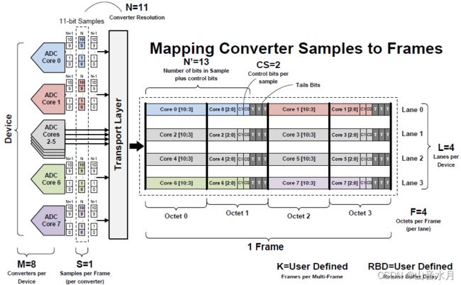
如图所示,为一个8通道采样,11位的AD,拥有4条传输通道,即M=8,N=11,L=4。根据上面的说明,N’=13(此处TI的定义和ADI的略有不同,ADI的定义下N’=16,但不影响理解),补充了2个控制位和3个尾位。要是同一帧的传输下,4条通道装下8个转换器的一个数据,需要设置F=4,即4个字节,每2个转换器共用一个传输通道,各自传输2个字节的数据。这张图一目了然的展示了连接参数对组帧方式的作用。
摘自《AD9689》
测试模式
JESD204B 协议定义了长传输层测试模式和短传输层测试模式,前者周期为多个帧周期,后者周期为单个帧周期,两种测试模式中采用的测试序列必须是可重复的,即在测试持续时间内按照一定周期重复出现。
在传输层测试模式中,将输入到传输层的数据样本替换为测试样本,通过验证接收端与发送端传输层中的测试样本是否完全一致,可以判断收发端传输层是否能够对数据样本进行正确的处理,将其映射为帧数据并对其进行解帧。
数据链路层
数据链路层中包括字符替换和还原模块、缓存器和 8B/10B 编解码模块。
对齐字符替换与还原
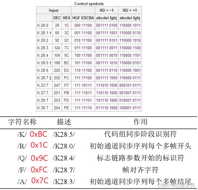
对齐字符的替换与帧数据是否经过加扰以及链路是否支持通道同步有关,如下所述,
| 方式 | 描述 |
|---|---|
| 收发端都支持通道同步,数据加扰 | 发送端检测到当前帧的最后一个八位字节等于0xFC,并且该八位字节不在多帧的末尾时,将其替换为控制字符/F/;当前多帧的最后一个八位字节等于 0x7C 时,将其替换为对齐字符/A/。接收端接收到字符/F/和/A/后将其还原为 0xFC和 0x7C |
| 收发端都支持通道同步,数据不加扰 | 发送端检测到当前帧与前一帧的最后一个八位字节相等,且当前帧的最后一个八位字节不在多帧的末尾时,将其替换为控制字符/F/,但如果在前一帧中已经进行了对齐字符的替换,则不对当前帧进行对齐字符替换;当前多帧的最后一个八位字节与前一帧的最后一个八位字节相等时,将其替换为控制字符/A/。接收端接收到字符/F/和/A/后将其还原为与前一帧最后一个八位字节相等的数据 |
| 收发端至少有一侧不支持通道同步,数据加扰 | 发送端检测到当前帧的最后一个八位字节等于 D28.7 时,将其替换为控制字符/F/。接收端接收到字符/F/后将其还原为 D28.7 |
| 收发端至少有一侧不支持通道同步,数据不加扰 | 发送端检测到当前帧与前一帧的最后一个八位字节相等时,将其替换为控制字符/F/,但如果在前一帧中已经进行了对齐字符的替换,则不对当前帧进行对齐字符替换。接收端接收到字符/F/后将其还原为与前一帧最后一个八位字节相等的数据 |
数据链路建立与维护
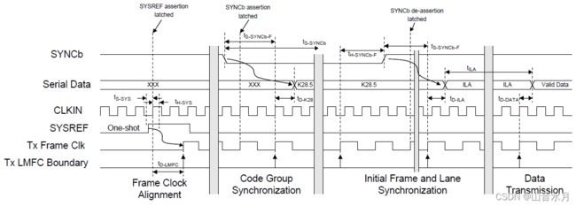
数据链路的建立分为三步:代码组同步(CGS)、初始通道同步(ILS)、传输用户数据。
物理层
时钟
器件时钟
- 器件时钟是 JESD204B 系统中的时基参考
- 时钟发生器电路负责从源时钟产生所有器件时钟,发送端和接收端设备从时钟发生器电路接收它们的器件时钟
- 器件时钟可具有与帧时钟或多帧时钟不同的周期,并且,器件负责从器件时钟产生帧时钟和多帧时钟。
- 器件时钟的频率和抖动特性会直接影响整个 JESD204B 链路中数据传输的稳定性,在频率较高时,需要使用差分信号形式传输
帧时钟/多帧时钟
- 所有发送端和接收端设备中的帧时钟周期必须分别相同
- 所有发送端和接收端设备中的多帧时钟周期必须分别相同
- 每个设备中的帧时钟和多帧时钟必须由同一时钟源产生且相位对齐
- 对于采用子类 1 的设备,在 SYSREF 信号有效时,帧时钟和本地多帧时钟的相位由器件时钟的时钟沿决定
- 对于采用子类 2 的设备,LMFC 的相位由 SYNC~上升沿决定;在 SYNC~信号无效时,帧时钟的相位由调整时钟决定
调整时钟
调整分辨率
- 调整分辨率定义为:可以对 LMFC 相位进行调整的最小步长
- 调整分辨率由链路设备(转换器或逻辑处理器件)中频率最高的器件时钟决定
- 如果调整分辨率小于转换器的器件时钟周期和帧时钟周期,则转换器需要从其器件时钟产生一个高速的调整时钟来满足链路的调整分辨率
调整时钟
- 该时钟的周期与调整分辨率相同,且可以通过控制接口改变其周期
- 可以通过调整时钟的上升沿对齐帧时钟和 LMFC
- 调整时钟与器件时钟相位对齐,便于对其进行定时检测
各时钟关系图
各协议层时钟使用情况
Xilinx IP
Ports
Basic Generic Clocking Schemes
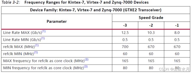
- 使用单独的 refclk 和 glblclk 输入分别作为收发器参考时钟和内核时钟
- 参考时钟和核心时钟是物理上独立的时钟,可以在独立的频率下运行,没有额外的限制
- 参考时钟可以在所选线路速率的收发器限制范围内以任何频率运行,核心时钟始终以所需的速率运行(串行线路速率的 1/40)
Subclass 1 Operation
- FPGA 的Device Clock是 FPGA 逻辑时钟(tx_core_clk 或 rx_core_clk)
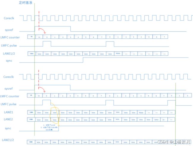
- SYSREF 信号作为Tx Device和Rx Device共用的参考信号,用于产生LMFC脉冲信号
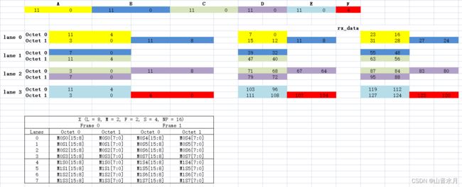
- 有一个LMFC计数器,在SYSREF的边沿(上升沿或下降沿可设)进行复位;计数器对一个多帧(multiframe)的字节(octets)进行计数(一个multiframe对应K*F个字节)(由于rx_data是四字节的Lane倍,则1 tx_core_clk cycles -4octets,那么,对于一个包含32 octets的多帧,LMFC计数器的范围是0-7)
- 在断言时,接收设备将其内部的LMFC 与输入的 SYSREF 信号对齐,并将 SYNC~信号拉高;
- 当发送设备检测到 SYNC~ 信号变为高电平时,它会等到下一个 LMFC才开始发送数据(如果支持 ILA 生成,就发送 ILA 序列;否则发送正常帧数据)
- 当接收设备检测到所有通道都输入有效数据时,会对输入数据进行缓存;在下一个 LMFC 的交叉点时,会从缓存中获取数据
Rx example仿真
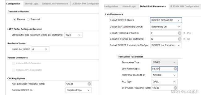
IP核设置
仿真
产生ILA序列
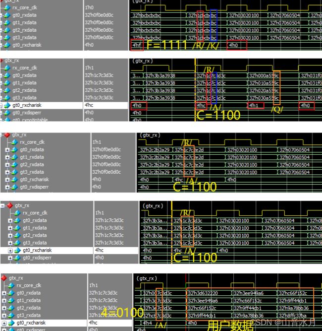
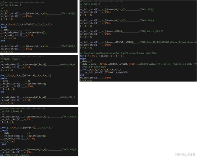
产生ILA序列的仿真代码如下,基本和AD9680要求的一致,
以下摘自《AD9680手册》
CGS是JESD204B接收设备找到数据流中10位符号间界限的过程;在CGS阶段,JESD204B传送模块传送/K28.5/字符;接收设备必须使用时钟数据恢复(CDR)技术,在输入数据流中定位/K28.5/字符。
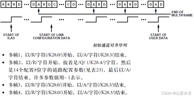
CGS阶段之后是ILAS阶段,它在下一LMFC边界开始;ILAS由4个多帧组成,/R/字符表示开始,/A/字符表示结束。ILAS从发送/R/字符开始,然后发送一个多帧的0至255斜坡数据。在第二个多帧发送链路配置数据,从第三个字符开始。第二个字符是/Q/字符,用以确认随后是链路配置数据。所有未定义数据时隙都用斜坡数据填充。ILAS序列从不加扰。
产生各个lane的数据;接收各个lane的数据
博文链接
JESD204接口调试总结——Xilinx JESD204B IP testbench解析
【Xilinx JESD204B】针对JESD204B的一些问题解答
Xilinx JESD204B数据手册的理解
jesd204b高速ad/da ad9172 AD9689调试记录
