stm32学习笔记:GPIO输入
1、寄存器输入输出函数
//读取输入数据寄存器某一个端口的输入值,参数用来指定某一个端口,返回值是
uint8_t类型,用来代表高低电平(读取按键的值)

uint8_t GPIO_ReadInputDataBit(GPIO_TypeDef* GPIOx, uint16_t GPIO_Pin);

//读取整个输入数据寄存器,参数用来指定外设,uint16_t是一个16位的数据,每一位代表一个端口值
uint16_t GPIO_ReadInputData(GPIO_TypeDef* GPIOx);

//读取输出寄存器
uint8_t GPIO_ReadOutputDataBit(GPIO_TypeDef* GPIOx, uint16_t GPIO_Pin);

//读取输出寄存器
uint16_t GPIO_ReadOutputData(GPIO_TypeDef* GPIOx);
ReadInput:读取GPIO口
ReadOutput:输出模式下输出的值/电平
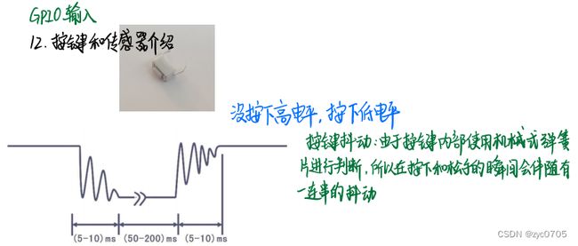
2、按下按键:低电平
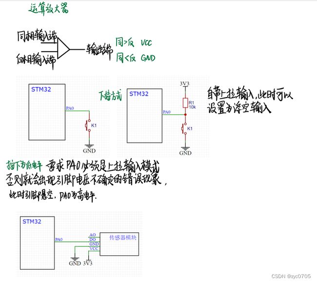
按键采取上拉输入模式,按下就接地,故没按下是高电平,按下的时候是低电平。
按键抖动 :由于按键内部使用机械式弹等片进行判新,所以在按下和松手的瞬间会伴随有一连串的抖动
GPIO_InitStructure.GPIO_Mode = GPIO_Mode_IPU;//上拉输入

上拉输入:可读取引脚电平,内部连接上拉电阻,悬空时默认高电平
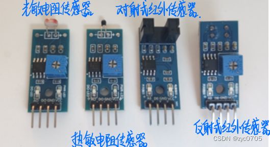
传感器元件的电阻会随看外界模拟量的变化而变化,通过领随电阻证即可得到模拟电压输出,再通过与电压比较器进行二值化即可得列数字电压输出
3、主要代码
(1)获取按键的值(按键接在B1和B11,led灯接在A1和A2)
//读取按键值的函数
uint8_t Key_GetNum(void)
{
	uint8_t KeyNum = 0;
	//读取GPIO端口的功能
	if(GPIO_ReadInputDataBit(GPIOB, GPIO_Pin_1)==0)   //按下
	{
		Delay_ms(20);
		while((GPIO_ReadInputDataBit(GPIOB, GPIO_Pin_1)==0));    //检测按键松手
		Delay_ms(20);
		KeyNum = 1;
	}
	if(GPIO_ReadInputDataBit(GPIOB, GPIO_Pin_11)==0)
	{
		Delay_ms(20);
		while((GPIO_ReadInputDataBit(GPIOB, GPIO_Pin_11)==0));
		Delay_ms(20);
		KeyNum = 2;
	}
	return KeyNum;
}
(2)调用按键中的函数
while(1)
	{
		KeyNum = Key_GetNum();
		if(KeyNum == 1)
		{
			LED1_ON();
		}
		if(KeyNum == 2)
		{
			LED1_OFF();
		}
	}
4、全部代码:
一、按键控制灯
(1)key.c
#include "stm32f10x.h"                  // Device header
#include "Delay.h"
void Key_Init(void)
{
	RCC_APB2PeriphClockCmd(RCC_APB2Periph_GPIOB,ENABLE);

	GPIO_InitTypeDef GPIO_InitStructure;
	GPIO_InitStructure.GPIO_Mode = GPIO_Mode_IPU;
	GPIO_InitStructure.GPIO_Pin = GPIO_Pin_1 | GPIO_Pin_11;
	GPIO_InitStructure.GPIO_Speed = GPIO_Speed_50MHz;
   GPIO_Init(GPIOB,&GPIO_InitStructure);

}
//读取按键值的函数
uint8_t Key_GetNum(void)
{
	uint8_t KeyNum = 0;
	//读取GPIO端口的功能
	if(GPIO_ReadInputDataBit(GPIOB, GPIO_Pin_1)==0)   //按下
	{
		Delay_ms(20);
		while((GPIO_ReadInputDataBit(GPIOB, GPIO_Pin_1)==0));    //检测按键松手
		Delay_ms(20);
		KeyNum = 1;
	}
	if(GPIO_ReadInputDataBit(GPIOB, GPIO_Pin_11)==0)
	{
		Delay_ms(20);
		while((GPIO_ReadInputDataBit(GPIOB, GPIO_Pin_11)==0));
		Delay_ms(20);
		KeyNum = 2;
	}
	return KeyNum;
}
(2)key.h
#ifndef __KEY_H
#define __KEY_H

void Key_Init(void);
uint8_t Key_GetNum(void);

#endif
(3)led
#include "stm32f10x.h"                  // Device header   头文件

void LED_Init(void)     //LED初始化函数
{
	RCC_APB2PeriphClockCmd(RCC_APB2Periph_GPIOA,ENABLE);

	GPIO_InitTypeDef GPIO_InitStructure;      //配置端口模式
	GPIO_InitStructure.GPIO_Mode = GPIO_Mode_Out_PP;
	GPIO_InitStructure.GPIO_Pin = GPIO_Pin_1 | GPIO_Pin_2;
	GPIO_InitStructure.GPIO_Speed = GPIO_Speed_50MHz;
   GPIO_Init(GPIOA,&GPIO_InitStructure);

	GPIO_SetBits(GPIOA, GPIO_Pin_1 | GPIO_Pin_2);//关闭LED
}

void LED1_ON(void)              //控制LED开关灯
{
	GPIO_ResetBits(GPIOA, GPIO_Pin_1);
}
void LED1_OFF(void)
{
	GPIO_SetBits(GPIOA, GPIO_Pin_1);
}
void LED1_Turn(void)
{
	if(GPIO_ReadOutputDataBit(GPIOA,GPIO_Pin_1)==0)
	{
		GPIO_SetBits(GPIOA,GPIO_Pin_1);            //再按一下置为1
	}
	else
	{
		GPIO_ResetBits(GPIOA,GPIO_Pin_1);
	}
}
void LED2_ON(void)
{
	GPIO_ResetBits(GPIOA, GPIO_Pin_2);
}
void LED2_OFF(void)
{
	GPIO_SetBits(GPIOA, GPIO_Pin_2);
}
void LED2_Turn(void)
{
	if(GPIO_ReadOutputDataBit(GPIOA,GPIO_Pin_2)==0)
	{
		GPIO_SetBits(GPIOA,GPIO_Pin_2);
	}
	else
	{
		GPIO_ResetBits(GPIOA,GPIO_Pin_2);
	}
}
(4)led.h
#ifndef __LED_H
#define __LED_H

void LED_Init(void);
void LED1_ON(void);
void LED1_OFF(void);
void LED1_Turn(void);
void LED2_ON(void);
void LED2_OFF(void);
void LED2_Turn(void);

#endif
(5)主函数
#include "stm32f10x.h"                  // Device header
#include "Delay.h"
#include "LED.h"
#include "Key.h"

uint8_t KeyNum;          //存储键码的返回值

int main(void)
{
	LED_Init();
	Key_Init();

	while(1)
	{
		KeyNum = Key_GetNum();
		if(KeyNum == 1)
		{
			LED1_ON();
		}
		if(KeyNum == 2)
		{
			LED1_OFF();
		}
	}
}
二、光敏传感器控制蜂鸣器
当遮住光线时,输出指示灯灭,代表输出高电平,有光线时,输出指示灯亮,代表输出低电平
(6)Buzzer.c
#include "stm32f10x.h"                  // Device header

void Buzzer_Init(void)
{
	RCC_APB2PeriphClockCmd(RCC_APB2Periph_GPIOB, ENABLE);

	GPIO_InitTypeDef GPIO_InitStructure;
	GPIO_InitStructure.GPIO_Mode = GPIO_Mode_Out_PP;
	GPIO_InitStructure.GPIO_Pin = GPIO_Pin_12;
	GPIO_InitStructure.GPIO_Speed = GPIO_Speed_50MHz;
	GPIO_Init(GPIOB, &GPIO_InitStructure);

	GPIO_SetBits(GPIOB, GPIO_Pin_12);
}

void Buzzer_ON(void)
{
	GPIO_ResetBits(GPIOB, GPIO_Pin_12);
}

void Buzzer_OFF(void)
{
	GPIO_SetBits(GPIOB, GPIO_Pin_12);
}

void Buzzer_Turn(void)
{
	if (GPIO_ReadOutputDataBit(GPIOB, GPIO_Pin_12) == 0)
	{
		GPIO_SetBits(GPIOB, GPIO_Pin_12);
	}
	else
	{
		GPIO_ResetBits(GPIOB, GPIO_Pin_12);
	}
}
(7)Buzzer.h
#ifndef __BUZZER_H
#define __BUZZER_H

void Buzzer_Init(void);
void Buzzer_ON(void);
void Buzzer_OFF(void);
void Buzzer_Turn(void);

#endif
(8)LightSensor.c
#include "stm32f10x.h"                  // Device header

void LightSensor_Init(void)
{
	RCC_APB2PeriphClockCmd(RCC_APB2Periph_GPIOB, ENABLE);

	GPIO_InitTypeDef GPIO_InitStructure;
	GPIO_InitStructure.GPIO_Mode = GPIO_Mode_IPU;//上拉模式
	GPIO_InitStructure.GPIO_Pin = GPIO_Pin_13;
	GPIO_InitStructure.GPIO_Speed = GPIO_Speed_50MHz;
	GPIO_Init(GPIOB, &GPIO_InitStructure);
}

uint8_t LightSensor_Get(void)
{
	return GPIO_ReadInputDataBit(GPIOB, GPIO_Pin_13);
}
(9)LightSensor.h
#ifndef __LIGHT_SENSOR_H
#define __LIGHT_SENSOR_H

void LightSensor_Init(void);
uint8_t LightSensor_Get(void);

#endif
(10)主函数
#include "stm32f10x.h"                  // Device header
#include "Delay.h"
#include "Buzzer.h"
#include "LightSensor.h"

int main(void)
{
	Buzzer_Init();
	LightSensor_Init();

	while (1)
	{
		if(LightSensor_Get()==1)       //光线暗
		{
			Buzzer_ON();
		}
		else
		{
			Buzzer_OFF();
		}
	}
} 


