FPGA project : uart232_ram_vga
重点学习:
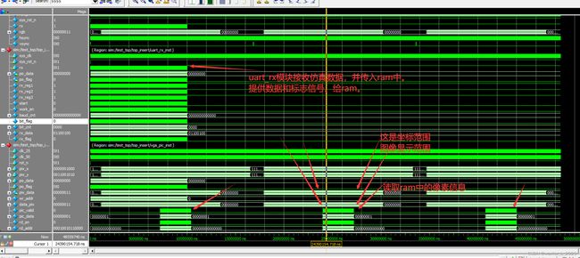
本实验重点学习了双口ram解决多bit跨时钟域同步处理的问题。
其实signal port ram,它的输入口和输出口分别用不同的时钟,也可以解决这个问题。
让我意识到的比较重要的事情:
1,代码设计中,一些大于10的数字,尽量用parameter设定一些可以重传的参数来代替。因为这样方便仿真修改。我就是之前写uart_rx模块,数字啥的没用参数替代。这个实验中仿真时需要修改参数,然后重新修改了uart_rx代码。使得仿真时间大大缩短,很方便。
2,在vga_pic模块中模拟产生的ram,读完数据后,ram里面的数据并没有消失,还在。
写数据:在时钟上升沿,写使能拉高,与此同时要有对应的地址与数据。然后数据就写进对应的地址里面了。
读数据:在时钟上升沿,读使能拉高,与此同时给出地址,然后数据就都出来了。值得一提的是,数据会滞后一个时钟周期(相对于读使能与地址),说明ram内部用的时序逻辑嘛。
3, task input ...如果写在task内部了。那么在task name 后面就不要加括号了。否则modulism会报错。
module vga_pic (
    input       wire            clk_25  , // ram 的输出时钟,也是vga图像的时钟。
    input       wire            clk_50  , // ram 的输入时钟
    input       wire            rst_n   , // 经过系统复位和pll的locked相与后的复位。
    input       wire    [9:0]   pix_x   ,
    input       wire    [9:0]   pix_y   ,
    input       wire    [7:0]   po_data , // 写入的数据的数据
    input       wire            po_flag , // 用作ram的读使能。

    output      wire    [7:0]   pix_data
);
    // parameter
    parameter   H_VALID = 10'd640    ,
                V_VALID = 10'd480    ;

    parameter   PIC_SIZE= 14'd1_0000 ,
                H_PIC   = 10'd100    ,
                V_PIC   = 10'd100    ;

    parameter   RED     = 8'b1110_0000 ,
                GREEN   = 8'b0001_1100 ,
                BLUE    = 8'b0000_0011 ,
                WHITE   = 8'b1111_1111 ,
                BLACK   = 8'b0000_0000 ;

    // reg signal define
    reg     [13:0]  wr_addr  ;  // ram 的写地址。
    reg     [ 7:0]  data_pix ;  // 彩条像素
    reg             pic_valid; // 图片有效
    wire    [ 7:0]  pic_data ; // 图片像素
    reg             rd_en    ; // ram读使能
    reg     [13:0]  rd_addr  ;

/************************************************************************/
    // reg     [13:0]  wr_addr  ;  // ram 的写地址。
    always @(posedge clk_50 or negedge rst_n) begin
        if(~rst_n) begin
            wr_addr <= 14'd0 ;
        end else begin
            if(po_flag) begin
                if(wr_addr == 9999) begin // 记到最大的地址后归零。
                    wr_addr <= 14'd0 ;
                end else begin
                    wr_addr <= wr_addr + 1'b1 ;
                end
            end else begin
                wr_addr <= wr_addr ;
            end
        end
    end

    // reg     [ 7:0]  data_pix ;  // 彩条像素
    always @(posedge clk_25 or negedge rst_n) begin
        if(~rst_n) begin
            data_pix <= BLACK ;
        end else begin
            if(pix_y >= 0 && pix_y <= (V_VALID / 5 - 1))
                data_pix <= RED ;
            else if((pix_y >= V_VALID / 5) && pix_y <= ((V_VALID / 5 ) * 2) - 1)
                data_pix <= GREEN ;
            else if((pix_y >= (V_VALID / 5) * 2) && pix_y <= ((V_VALID / 5 ) * 3) - 1)
                data_pix <= BLUE ;
            else if((pix_y >= (V_VALID / 5) * 3) && pix_y <= ((V_VALID / 5 ) * 4) - 1)
                data_pix <= WHITE ;
            else if((pix_y >= (V_VALID / 5) * 4) && pix_y <= (V_VALID  - 1))
                data_pix <= BLACK ;
            else
                data_pix <= BLACK ;
        end // 先不写else 一会看编译是否会通过。
    end
    // reg             pic_valid; // 图片有效
    always @(posedge clk_25 or negedge rst_n) begin
        if(~rst_n) begin
            pic_valid <= 1'b0 ;
        end else begin
            if(pix_x >= 269 && pix_x <= 368 && pix_y >= 190 && pix_y <= 289) begin
                pic_valid <= 1'b1 ;
            end else begin
                pic_valid <= 1'b0 ;
            end
        end
    end
    // wire    [ 7:0]  pic_data ; // 图片像素
    // 图片像素存在了ram中,所以只需要取出来就是图片像素了。
    // reg             rd_en    ; // ram读使能
    always @(posedge clk_25 or negedge rst_n) begin
        if(~rst_n) begin
            rd_en <= 1'b0 ;
        end else begin
            if(pix_x >= 268 && pix_x <= 367 && pix_y >= 190 && pix_y <= 289) begin
                rd_en <= 1'b1 ;
            end else begin
                rd_en <= 1'b0 ;
            end
        end
    end
    // reg     [13:0]  rd_addr  ;
    always @(posedge clk_25 or negedge rst_n) begin
        if(~rst_n) begin
            rd_addr <= 14'd0 ;
        end else begin
            if(rd_en) begin
                if(rd_addr == 9999) begin
                    rd_addr <= 14'd0 ;
                end else begin
                    rd_addr <= rd_addr + 1'b1 ;
                end
            end else begin
                rd_addr <= rd_addr ;
            end
        end
    end

/**********************output signal define**************************************/
    // wire    [7:0]   pix_data ;
    assign pix_data = (pic_valid == 1'b1) ? pic_data : data_pix ;
/******************例化双口ram*******************/
ram_10000_double ram_10000_double_insert(
	.data                   ( po_data ) ,
	.inclock                ( clk_50  ) ,
	.outclock               ( clk_25  ) ,
	.rdaddress              ( rd_addr ) ,
	.wraddress              ( wr_addr ) ,
	.wren                   ( po_flag ) ,
	.q                      ( pic_data)
);

endmodule
module top(
    input       wire            sys_clk     ,
    input       wire            sys_rst_n   ,
    input       wire            rx          ,

    output      wire    [7:0]   rgb         ,
    output      wire            hsync       ,
    output      wire            vsync
);

    // 例化间连线
    wire            rst_n       ;
    wire    [7:0]   po_data     ;
    wire            po_flag     ;
    wire    [7:0]   pix_data    ;
    wire    [9:0]   pix_x       ;
    wire    [9:0]   pix_y       ;
    wire            clk_25      ;
    wire            clk_50      ;

pll	pll_inst (
    .sys_rst_n              ( sys_rst_n     ) ,
	.areset                 ( ~sys_rst_n    ) ,
	.inclk0                 ( sys_clk       ) ,
	.c0                     ( clk_25        ) ,
	.c1                     ( clk_50        ) ,
	.locked                 ( rst_n         )
);

uart_rx uart_rx_inst(
    .sys_clk                ( clk_50        ) ,
    .sys_rst_n              ( rst_n         ) ,
    .rx                     ( rx            ) ,

    .po_data                ( po_data       ) ,
    .po_flag                ( po_flag       )
);

vga_ctrl vga_ctrl_inst(
    .vga_clk                ( clk_25        ) ,
    .vga_rst_n              ( rst_n         ) ,
    .pix_data               ( pix_data      ) ,

    .hsync                  ( hsync         ) ,
    .vsync                  ( vsync         ) ,
    .pix_x                  ( pix_x         ) ,
    .pix_y                  ( pix_y         ) ,
    .rgb                    ( rgb           )
);

vga_pic vga_pic_inst(
    .clk_25                 ( clk_25        ) ,
    .clk_50                 ( clk_50        ) ,
    .rst_n                  ( rst_n         ) ,
    .pix_x                  ( pix_x         ) ,
    .pix_y                  ( pix_y         ) ,
    .po_data                ( po_data       ) ,
    .po_flag                ( po_flag       ) ,

    .pix_data               ( pix_data      )
);


endmodule
`timescale 1ns/1ns
module test_top();
reg sys_clk ;
reg sys_rst_n ;
reg rx ;
wire [7:0] rgb ;
wire hsync ;
wire vsync ;
reg [7:0] data_mem [9999:0];
top top_insert(
.sys_clk ( sys_clk ) ,
.sys_rst_n ( sys_rst_n ) ,
.rx ( rx ) ,
.rgb ( rgb ) ,
.hsync ( hsync ) ,
.vsync ( vsync )
);
defparam top_insert.uart_rx_inst.CLK_FREQ = 5 ;
defparam top_insert.uart_rx_inst.UART_BPS = 1 ;
parameter CYCLE = 20 ;
initial begin
sys_clk = 1'b1 ;
sys_rst_n <=1'b0 ;
#(CYCLE) ;
sys_rst_n <=1'b1 ;
end
always #(CYCLE / 2) sys_clk = ~sys_clk ;
initial begin
$readmemh ("D:/intel_FPGA/VScodedocument/EmbedFire/31 rs232_vga/matlab/data_test.txt",data_mem);
end
initial begin
rx <= 1'b1 ;
#(CYCLE * 10) ;
rx_byte ;
end
task rx_byte;
integer j ; // j 是存储器的地址。
for (j = 0;j < 10000 ;j = j + 1 ) begin
rx_bit(data_mem[j]) ; // 没有输入端口,自然不需要输入参数。
end
endtask
task rx_bit;
input [7:0]data ;
integer i ;
for (i = 0;i < 10 ;i = i + 1 ) begin
case (i)
0:rx <= 1'b0;
1:rx <= data[0];
2:rx <= data[1];
3:rx <= data[2];
4:rx <= data[3];
5:rx <= data[4];
6:rx <= data[5];
7:rx <= data[6];
8:rx <= data[7];
9:rx <= 1'b1;
default: rx <= 1'b1;
endcase
#(5 * CYCLE) ;
end
endtask
endmodule


