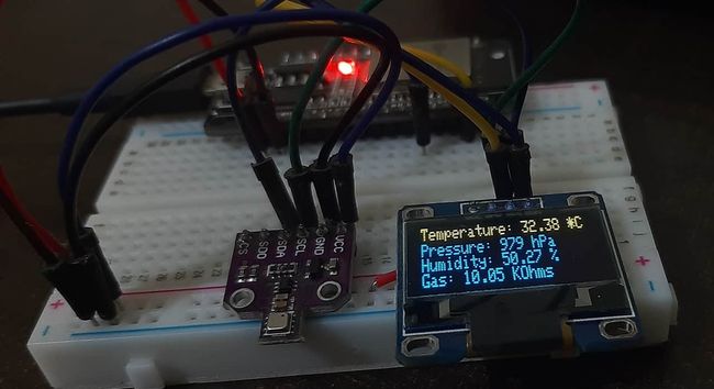
使用Arduino IDE的BME680 和 ESP32(气体、压力、温度、湿度)
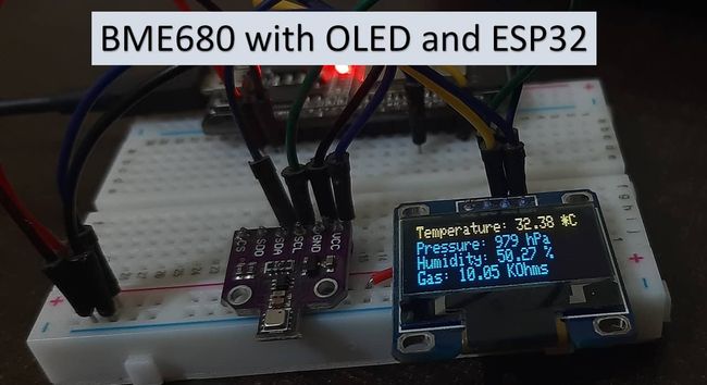
在本教程中,我们将学习使用 Arduino IDE 将 BME680 传感器与 ESP32 连接。BME680环境传感器,用于测量环境温度、气压、相对湿度和气体(VOC)或室内空气质量(IAQ)。我们将学习如何使用 Arduino 核心编程将其与 ESP32 连接。为了进行演示,首先,我们将使用一个简单的 Arduino IDE 代码来读取 BME680 传感器数据并将其显示在 Arduino IDE 的串行监视器上。此外,我们还将看到一个在 OLED 显示屏上显示 BME680 传感器读数的示例。
先决条件
在开始本课程之前,请确保您熟悉并安装了最新版本的 Arduino IDE。另外,请确保您在 Arduino IDE 中安装了 ESP32 插件。
BME680介绍
BME680是一款四合一电力驱动传感器,集成了温度、压力、湿度和气体检测传感器。它的工作电压为1.8-3.8V,并通过I2C和SPI协议与其他微控制器通信。该传感器用于跟踪空气质量、湿度指示器、天气趋势、家庭自动化、控制和 GPS 增强等领域。
工作范围和精度
BME680 的一些主要 特性包括:
- 温度测量:测量环境温度,精度为±1.0℃,工作范围为-40至85℃。
- 相对湿度测量:测量相对湿度,响应速度快,精度为±3%,工作范围为0-100%。
- 压力测量:以±1 hPa绝对精度测量气压,以±1米精度测量海拔高度。压力操作范围为 300-1100 hPa。
| 准确性 | 工作范围 | |
|---|---|---|
| 温度 | ±1.0℃ | -40 至 85 ℃ |
| 湿度 | ±3% | 0-100% |
| 压力 | ±1 hPa | 300-1100 hPa |
- 气体测量:检测包括挥发性有机化合物 (VOC) 在内的多种气体,从而确定室内空气质量。
- 由于其紧凑的尺寸和低功耗运行,它适用于移动应用、智能手表和导航系统。
与 BME280 相比,BME680 是一款独特且更新的传感器,因为它包含小尺寸 MOX(金属氧化物)传感器。
气体传感器
BME680传感器可以测定环境中污染物/VOC的数量,例如一氧化碳、乙烷、异戊二烯/2-甲基-1,3丁二烯、丙酮和乙醇。VOC 通过金属氧化物层上吸附的氧分子来检测。它的实际检测是通过改变MOX传感器的阻值原理来完成的。每当 MOX 与空气中的污染物接触时,传感器的电阻就会随着污染物浓度的变化而变化。这意味着空气中污染物数量较多会导致传感器的电阻显着降低。同样,随着空气中 VOC 浓度的降低,传感器的电阻也会明显升高。
注意:BME680 气体传感器不是 CO2 或乙醇测量传感器。它从空气中的VOC中得到CO2的相对值,但不能用于直接测量CO2。
与所有其他气体传感器一样,BME680 每次也会给出不同的结果。为了确保更高的准确性,我们必须根据已知源对其进行校准,然后绘制其曲线。由于传感器在初次使用期间灵敏度水平不是恒定的,因此最初建议运行四十八小时,随后可以在每次使用前将其调低至三十分钟。
BME680 模块
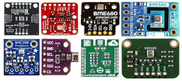
市场上有多种不同尺寸和端子数量的 BME680 传感器。但所有模块都通过SPI但所有模块都通过SPI和I2C接口提供数据,我们可以使用相同的 Arduino 草图来获取传感器读数。其中一些如下所示:
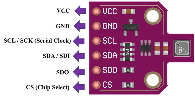
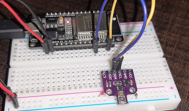
可以根据自己的方便以及要连接的微控制器类型来选择模块。在本文中,我们将使用带有 6 个端子的 BME680 传感器,如下所示。它有 4 个 SPI 和两个 I2C 端子。
引脚图
下图显示了BME680传感器的引脚排列:
| 引脚 | 功能描述 |
|---|---|
| VCC | 该引脚为传感器供电。 |
| GND | 这是电源和逻辑的公共接地引脚。 |
| SCL | 当使用 I2C 协议时,该引脚充当 SCL 或串行时钟引脚;当使用 SPI 协议时,该引脚充当 SCK 或 SPI 的串行引脚。它是芯片的输入。 |
| SDA | 当使用 I2C 协议时,该引脚充当 SDA 或串行数据引脚,而当使用 SPI 协议时,该引脚充当 SDI 或串行数据输入,也称为 MOSI(“主输出从输入”)。这用作传感器的 I2C/SPI 输入。 |
| SDO | 这是用于 SPI 通信的 SDO(从机数据输出)/MISO(主机输入从机输出)引脚。该引脚用作传感器的 SPI 输出。 |
| CS | 这是 SPI 通信中使用的片选引脚。充当传感器的输入。 |
BME680 I2C 和 SPI 接口
在本节中,我们将了解如何将 BME680 传感器模块与 ESP32 连接。如前所述,BME680 提供两种接口,例如 I2C 和 SPI。我们可以使用 SPI 或 I2C 接口将传感器与 ESP32 连接。我们将在下一节中展示这两种情况的连接。
与 ESP32 的 I2C 接口
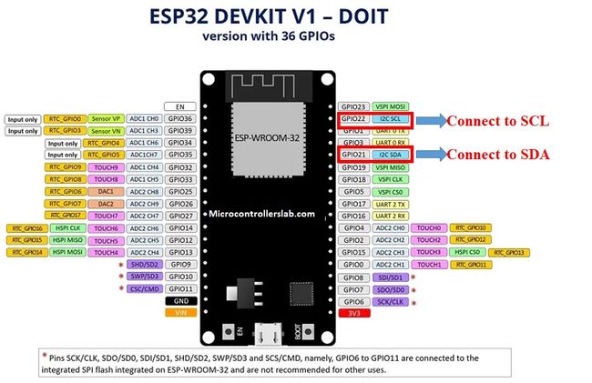
如果要使用 I2C 接口将 BME680 传感器与 ESP32 连接,则应根据这些 SCL 和 SDA 引脚进行 ESP32 板的连接。
| BME680 | ESP32 |
|---|---|
| VCC | VCC=3.3V |
| GND | GND |
| SCL | GPIO22 |
| SDA | GPIO21 |
将ESP32的VCC引脚与模块的3.3V VCC引脚连接即可上电。两个设备的两个接地将连接在一起。BME680 的 SCL 引脚将与 ESP32 的默认 SCL 引脚连接。同样,SDA 引脚将与 ESP32 的默认 SDA 引脚连接。
注意:如果我们使用 ESP32 的其他 GPIO 引脚进行 I2C 通信,我们可以在 Arduino 草图中定义其他引脚。我们不必使用默认的 I2C 引脚。
ESP32 I2C 引脚
上述 I2C 引脚为默认设置。如果我们想更改 GPIO 引脚,我们必须在代码中设置它们。下图显示了 ESP32 的引脚排列。
与 ESP32 的 SPI 接口
如果要使用 SPI 接口将 BME680 传感器与 ESP32 连接,则应根据这些 MOSI、MISO 和 SCK 引脚将 ESP32 与传感器连接。因为SPI协议使用MOSI/SDI、MISO/SDO和SCK引脚。
| BME680 | ESP32 |
|---|---|
| VCC | VCC=3.3V |
| GND | GND |
| SCL(SPI 的 SCK) | GPIO18 |
| SDA(SPI 的 SDI/MOSI) | GPIO23 |
| SDO / MISO | GPIO19 |
| CS | GPIO5 |
VCC 引脚将连接 ESP32 模块的 3.3V 电源来供电。两个设备的两个接地将连接在一起。BME680 的 SCL 引脚将与 ESP32 的默认 SCK/CLK 引脚连接。同样,SDA 引脚将与 ESP32 的默认 MOSI 引脚连接。SDO 引脚将与 ESP32 的默认 MISO 引脚连接,传感器的 CS 引脚也将与 ESP32 的默认 CS 引脚连接。
注:上表列出了 ESP32 默认的 SPI 引脚。但如果你想使用任何其他引脚,你需要在 Arduino sketch 中定义它们
如您所见,我们将使用 ESP32 模块的默认 I2C 和默认 SPI 引脚来连接传感器的相应引脚。如果您想根据自己的喜好更改引脚,可以在程序代码中处理。
使用哪个接口?
到目前为止,我们已经讨论了 BME680 的 SPI 和 I2C 接口,并学习了使用这两个接口将传感器与 ESP32 连接。但问题是我们应该使用哪种通信协议来从 BME680 读取数据。正如我们所见,SPI 需要四个引脚来进行通信。相反,I2C 需要两个引脚。然而,与 I2C 相比,SPI 的速度通常更快。因此,这是速度和引脚数量之间的权衡。简而言之,这取决于您的选择和应用。我们将使用 I2C 接口通过 ESP32 的默认 I2C 引脚获取传感器读数。
所需硬件
我们需要以下组件来连接 ESP32 板与 BME680 传感器。
- ESP32
- BME680模块
- 连接线
- 面包板
- 0.96英寸OLED显示屏
BME680 与 ESP32 连接图
按照下图原理图将 ESP32 与 BME680 连接,通过 I2C 通信进行接口。
按照下图原理图将 ESP32 与 BME680 连接,通过 SPI 通信进行接口:
在 Arduino 中安装 BME680 库
我们将使用 Arduino IDE 对带有 BME680 的 ESP32 板进行编程。在继续操作之前,请确保您已安装 ESP32 插件。
Arduino 为 BME680 提供了一个内置库,我们将启动它。为了使用 BME680 库的功能,我们还将安装“Adafruit_Sensor Library”。请按照以下步骤确保库的成功安装。
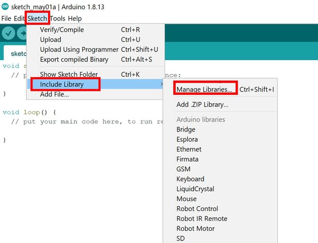
- 在 Arduino IDE 中,单击 Sketch > Include Library > Manage Library
库管理器窗口将打开。在搜索栏中输入“adafruit bme680”。单击安装按钮,如图所示。
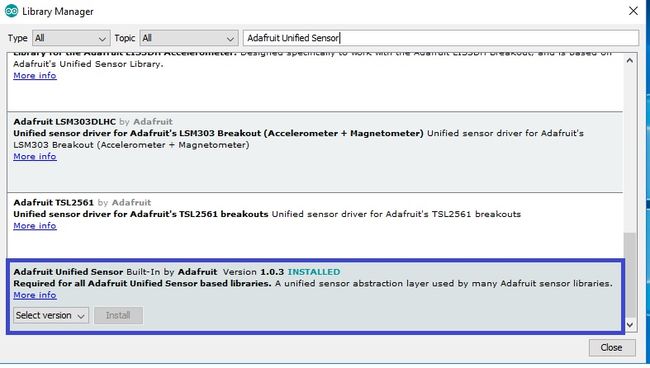
现在,我们将安装 Adafruit_Sensor 库。再次单击 Sketch > Include Library > Manage Library
在搜索栏中输入“adafruit Unified Sensor”并安装下面蓝色框中显示的库
ESP32 代码:在串行监视器上显示 BME680 值
让我们看一个显示传感器模块的温度、压力、湿度和气体读数的草图示例。安装上述库后,重新启动 IDE 并单击 File > Examples > Adafruit BME680 Library > bme680async。
这将打开一个名为 bme680async 的新文件,该文件读取传感器数据并将其显示在串行监视器上。您可以查看下面的代码:
#include
#include
#include
#include "Adafruit_BME680.h"

/*#define BME_SCK 18
#define BME_MISO 19
#define BME_MOSI 23
#define BME_CS 15*/

#define SEALEVELPRESSURE_HPA (1013.25)

Adafruit_BME680 bme; // I2C
//Adafruit_BME680 bme(BME_CS); // hardware SPI
//Adafruit_BME680 bme(BME_CS, BME_MOSI, BME_MISO, BME_SCK);

void setup() {
  Serial.begin(115200);
  while (!Serial);
  Serial.println(F("BME680 async test"));

  if (!bme.begin()) {
    Serial.println(F("Could not find a valid BME680 sensor, check wiring!"));
    while (1);
  }

  // Set up oversampling and filter initialization
  bme.setTemperatureOversampling(BME680_OS_8X);
  bme.setHumidityOversampling(BME680_OS_2X);
  bme.setPressureOversampling(BME680_OS_4X);
  bme.setIIRFilterSize(BME680_FILTER_SIZE_3);
  bme.setGasHeater(320, 150); // 320*C for 150 ms
}

void loop() {
  // Tell BME680 to begin measurement.
  unsigned long endTime = bme.beginReading();
  if (endTime == 0) {
    Serial.println(F("Failed to begin reading :("));
    return;
  }
  Serial.print(F("Reading started at "));
  Serial.print(millis());
  Serial.print(F(" and will finish at "));
  Serial.println(endTime);

  Serial.println(F("You can do other work during BME680 measurement."));
  delay(50); // This represents parallel work.
  // There's no need to delay() until millis() >= endTime: bme.endReading()
  // takes care of that. It's okay for parallel work to take longer than
  // BME680's measurement time.

  // Obtain measurement results from BME680. Note that this operation isn't
  // instantaneous even if milli() >= endTime due to I2C/SPI latency.
  if (!bme.endReading()) {
    Serial.println(F("Failed to complete reading :("));
    return;
  }
  Serial.print(F("Reading completed at "));
  Serial.println(millis());

  Serial.print(F("Temperature = "));
  Serial.print(bme.temperature);
  Serial.println(F(" *C"));

  Serial.print(F("Pressure = "));
  Serial.print(bme.pressure / 100.0);
  Serial.println(F(" hPa"));

  Serial.print(F("Humidity = "));
  Serial.print(bme.humidity);
  Serial.println(F(" %"));

  Serial.print(F("Gas = "));
  Serial.print(bme.gas_resistance / 1000.0);
  Serial.println(F(" KOhms"));

  Serial.print(F("Approx. Altitude = "));
  Serial.print(bme.readAltitude(SEALEVELPRESSURE_HPA));
  Serial.println(F(" m"));

  Serial.println();
  delay(2000);
}
示范
在 Arduino IDE 中,单击“工具”>“开发板”,然后选择“ESP32”。
现在,单击“工具”>“端口”并选择您正在使用的端口。现在,单击上传按钮上传代码。
将以下代码上传到 ESP32 开发板上后,按 ENABLE 按钮,如下所示:
您将看到串行监视器显示所有 BME680 传感器读数,例如气体、压力、温度和湿度,如下所示:
使用 Arduino IDE 在 OLED 显示屏上显示 BME680 传感器值
在本节中,我们将了解如何使用 ESP32 和 Arduino IDE 在 0.96 SSD1306 OLED 显示屏上显示气体、压力、温度和湿度值。
在 Arduino IDE 中安装 SSD1306 OLED 库
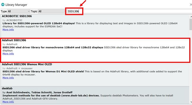
要在我们的项目中使用 OLED 显示屏,我们必须在 Arduino IDE 中安装 Adafruit SSD 1306 库。按照以下步骤即可成功安装。
打开 Arduino IDE 并单击 Sketch > Library > Manage Libraries
将打开以下窗口。
在搜索选项卡中输入“SSD1306”并安装 Adafruit SSD1306 OLED 库。
连接图 – OLED 与 ESP32 和 BME680
下表显示了将连接在一起的三个设备的端子。
| OLED显示屏 | ESP32 | BME680 |
|---|---|---|
| VCC | VCC=3.3V | VCC |
| GND | GND | GND |
| SCL | GPIO22 | SCL |
| SDA | GPIO21 | SDA |
组装电路如下图所示:
如上所示,我们已将所有 VCC 端子连接到 3.3V 电源。SCL 端子与 GPIO22 连接,SDA 端子与 GPIO21 连接。理由也很常见。
ESP32 代码:在 OLED 显示屏上显示 BME680 读数
组装完上述电路图后,将以下代码复制到您的 Arduino IDE 并将其上传到 ESP32。
组装完上述电路图后,将以下代码复制到您的 Arduino IDE 并将其上传到 ESP32。
/***************************************************************************
  This is a library for the BME680 gas, humidity, temperature & pressure sensor

  Designed specifically to work with the Adafruit BME680 Breakout
  ----> http://www.adafruit.com/products/3660

  These sensors use I2C or SPI to communicate, 2 or 4 pins are required
  to interface.

  Adafruit invests time and resources providing this open source code,
  please support Adafruit and open-source hardware by purchasing products
  from Adafruit!

  Written by Limor Fried & Kevin Townsend for Adafruit Industries.
  BSD license, all text above must be included in any redistribution
 ***************************************************************************/

#include
#include
#include
#include "Adafruit_BME680.h"
#include
#include

#define BME_SCK 13
#define BME_MISO 12
#define BME_MOSI 11
#define BME_CS 10

#define SEALEVELPRESSURE_HPA (1013.25)

Adafruit_BME680 bme; // I2C
//Adafruit_BME680 bme(BME_CS); // hardware SPI
//Adafruit_BME680 bme(BME_CS, BME_MOSI, BME_MISO,  BME_SCK);

Adafruit_SSD1306 display = Adafruit_SSD1306(128, 32, &Wire);

void setup() {
  Serial.begin(9600);
  Serial.println(F("BME680 test"));

  // by default, we'll generate the high voltage from the 3.3v line internally! (neat!)
  display.begin(SSD1306_SWITCHCAPVCC, 0x3C);  // initialize with the I2C addr 0x3C (for the 128x32)
  // init done
  display.display();
  delay(100);
  display.clearDisplay();
  display.display();
  display.setTextSize(1);
  display.setTextColor(WHITE);

  if (!bme.begin()) {
    Serial.println("Could not find a valid BME680 sensor, check wiring!");
    while (1);
  }

  // Set up oversampling and filter initialization
  bme.setTemperatureOversampling(BME680_OS_8X);
  bme.setHumidityOversampling(BME680_OS_2X);
  bme.setPressureOversampling(BME680_OS_4X);
  bme.setIIRFilterSize(BME680_FILTER_SIZE_3);
  bme.setGasHeater(320, 150); // 320*C for 150 ms
}

void loop() {
  display.setCursor(0,0);
  display.clearDisplay();

  if (! bme.performReading()) {
    Serial.println("Failed to perform reading :(");
    return;
  }
  Serial.print("Temperature = "); Serial.print(bme.temperature); Serial.println(" *C");
  display.print("Temperature: "); display.print(bme.temperature); display.println(" *C");

  Serial.print("Pressure = "); Serial.print(bme.pressure / 100.0); Serial.println(" hPa");
  display.print("Pressure: "); display.print(bme.pressure / 100); display.println(" hPa");

  Serial.print("Humidity = "); Serial.print(bme.humidity); Serial.println(" %");
  display.print("Humidity: "); display.print(bme.humidity); display.println(" %");

  Serial.print("Gas = "); Serial.print(bme.gas_resistance / 1000.0); Serial.println(" KOhms");
  display.print("Gas: "); display.print(bme.gas_resistance / 1000.0); display.println(" KOhms");

  Serial.println();
  display.display();
  delay(2000);
}
示范
要查看上述代码的演示,请将代码上传到 Arduino。但是,在上传代码之前,请确保从Tools > Board 选择 ESP32 板 ,并从Tools > Port选择 ESP32 板连接的正确 COM 端口 。
将代码上传到ESP32后,打开Arduino IDE的串行监视器并将波特率设置为115200。最后,我们可以在Arduino串行监视器和OLED显示屏上看到BME680读数,如下所示:
本文内容由IC先生电子商城www.mrchip.cn编辑整理发布,请勿转载。
