ZYNQ配置IIC接口读取eeprom和iictool使用
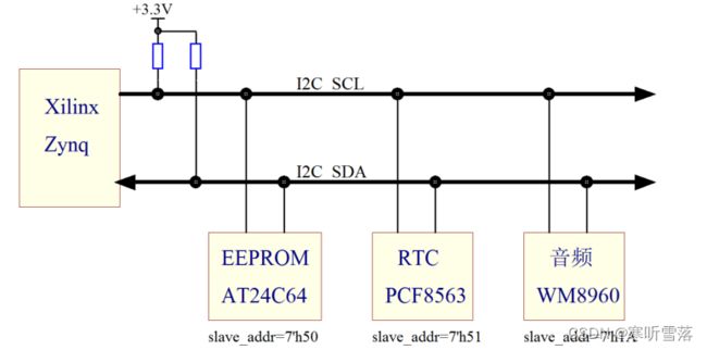
I2C 总线具备广泛的用途,比如寄存器的配置,EEPROM 的使用,更重要的是 I2C 总线上可以挂载非常多的外设。对于一些低速器件的访问非常节省 IO资源,由于是标准的总线接口,使用起来非常方便。I2C 总线支持双向传输,总线上需要上拉电阻。

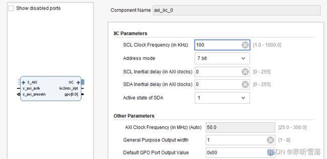
一,ZYNQ 裸机IIC读写EEPROM(AXI_IIC IP核模块读写EEPROM)
1,vivado驱动和配置

 2,添加约束
set_property IOSTANDARD LVCMOS33 [get_ports {iic_scl_io}]
set_property PACKAGE_PIN xxx [get_ports {iic_scl_io}]
set_property IOSTANDARD LVCMOS33 [get_ports {iic_sda_io}]
set_property PACKAGE_PIN yyy [get_ports {iic_sda_io}]
3,sdk读写代码: EEPROM24LC04芯片的读写为例
#include "xparameters.h"
#include "xiic.h"
#include "xil_exception.h"

#ifdef XPAR_INTC_0_DEVICE_ID
 #include "xintc.h"
#else
 #include "xscugic.h"
#endif
#define IIC_DEVICE_ID	XPAR_IIC_0_DEVICE_ID

#ifdef XPAR_INTC_0_DEVICE_ID
 #define INTC_DEVICE_ID	XPAR_INTC_0_DEVICE_ID
 #define IIC_INTR_ID	XPAR_FABRIC_AXI_IIC_0_IIC2INTC_IRPT_INTR
 #define INTC			XIntc
 #define INTC_HANDLER	XIntc_InterruptHandler
#else
 #define INTC_DEVICE_ID		XPAR_SCUGIC_SINGLE_DEVICE_ID
 #define IIC_INTR_ID		XPAR_FABRIC_AXI_IIC_0_IIC2INTC_IRPT_INTR
 #define INTC			 	XScuGic
 #define INTC_HANDLER		XScuGic_InterruptHandler
#endif

#define EEPROM_ADDRESS 		0x54	/* 0xA0 as an 8 bit number. */

#define IIC_MUX_ADDRESS 		0x74
#define IIC_EEPROM_CHANNEL		0x08

#define PAGE_SIZE   16

#define EEPROM_TEST_START_ADDRESS   128

/**************************** Type Definitions *******************************/
/*
 * The AddressType for ML300/ML310/ML410/ML510 boards should be u16 as the address
 * pointer in the on board EEPROM is 2 bytes.
 * The AddressType for ML403/ML501/ML505/ML507/ML605/SP601/SP605/KC705/ZC702
 * /ZC706 boards should be u8 as the address pointer in the on board EEPROM is
 * 1 bytes.
 */
typedef u8 AddressType;

/***************** Macros (Inline Functions) Definitions *********************/
/************************* Function Prototypes ******************************/
int IicEepromExample();
int EepromWriteData(u16 ByteCount);
int EepromReadData(u8 *BufferPtr, u16 ByteCount);
static int SetupInterruptSystem(XIic *IicInstPtr);
static void SendHandler(XIic *InstancePtr);
static void ReceiveHandler(XIic *InstancePtr);
static void StatusHandler(XIic *InstancePtr, int Event);
#ifdef IIC_MUX_ENABLE
static int MuxInit(void);
#endif
/************************** Variable Definitions *****************************/

XIic IicInstance;	/* The instance of the IIC device. */
INTC Intc; 	/* The instance of the Interrupt Controller Driver */
u8 WriteBuffer[sizeof(AddressType) + PAGE_SIZE];
u8 ReadBuffer[PAGE_SIZE];	/* Read buffer for reading a page. */
volatile u8 TransmitComplete;	/* Flag to check completion of Transmission */
volatile u8 ReceiveComplete;	/* Flag to check completion of Reception */
u8 EepromIicAddr;		/* Variable for storing Eeprom IIC address */
/************************** Function Definitions *****************************/

/*****************************************************************************/
/**
* Main function to call the High level EEPROM example.
*
* @param	None.
*
* @return	XST_SUCCESS if successful else XST_FAILURE.
*
* @note		None.
*
******************************************************************************/
int main(void)
{
	int Status;

	/*
	 * Run the EEPROM example.
	 */
	Status = IicEepromExample();
	if (Status != XST_SUCCESS) {
		return XST_FAILURE;
	}
	return XST_SUCCESS;

}

int IicEepromExample()
{
	u32 Index;
	int Status;
	XIic_Config *ConfigPtr;	/* Pointer to configuration data */
	AddressType Address = EEPROM_TEST_START_ADDRESS;
	EepromIicAddr = EEPROM_ADDRESS;

	/*
	 * Initialize the IIC driver so that it is ready to use.
	 */
	ConfigPtr = XIic_LookupConfig(IIC_DEVICE_ID);
	if (ConfigPtr == NULL) {
		return XST_FAILURE;
	}

	Status = XIic_CfgInitialize(&IicInstance, ConfigPtr,
			ConfigPtr->BaseAddress);
	if (Status != XST_SUCCESS) {
		return XST_FAILURE;
	}

	/*
	 * Setup the Interrupt System.
	 */
	Status = SetupInterruptSystem(&IicInstance);
	if (Status != XST_SUCCESS) {
		return XST_FAILURE;
	}

	/*
	 * Set the Handlers for transmit and reception.
	 */
	XIic_SetSendHandler(&IicInstance, &IicInstance,(XIic_Handler) SendHandler);
	XIic_SetRecvHandler(&IicInstance, &IicInstance,(XIic_Handler) ReceiveHandler);
	XIic_SetStatusHandler(&IicInstance, &IicInstance,(XIic_StatusHandler) StatusHandler);
#ifdef IIC_MUX_ENABLE
	Status =  MuxInit();
	if (Status != XST_SUCCESS)
    {
		return XST_FAILURE;
	}

#endif

	//Initialize the data to write and the read buffer.
	if (sizeof(Address) == 1) {
		WriteBuffer[0] = (u8) (EEPROM_TEST_START_ADDRESS);
		EepromIicAddr |= (EEPROM_TEST_START_ADDRESS >> 8) & 0x7;
	} else {
		WriteBuffer[0] = (u8) (EEPROM_TEST_START_ADDRESS >> 8);
		WriteBuffer[1] = (u8) (EEPROM_TEST_START_ADDRESS);
		ReadBuffer[Index] = 0;
	}

	for (Index = 0; Index < PAGE_SIZE; Index++) {
		WriteBuffer[sizeof(Address) + Index] = 0xFF;
		ReadBuffer[Index] = 0;
	}

	/*
	 * Set the Slave address.
	 */
	Status = XIic_SetAddress(&IicInstance, XII_ADDR_TO_SEND_TYPE,
				 EepromIicAddr);
	if (Status != XST_SUCCESS)
   {
		return XST_FAILURE;
	}


	/*
	 * Write to the EEPROM.
	 */
	Status = EepromWriteData(sizeof(Address) + PAGE_SIZE);
	if (Status != XST_SUCCESS) {
		return XST_FAILURE;
	}

	/*
	 * Read from the EEPROM.
	 */
	Status = EepromReadData(ReadBuffer, PAGE_SIZE);
	if (Status != XST_SUCCESS) {
		return XST_FAILURE;
	}

	/*
	 * Verify the data read against the data written.
	 */
	for (Index = 0; Index < PAGE_SIZE; Index++) {
		if (ReadBuffer[Index] != WriteBuffer[Index + sizeof(Address)]) {
			return XST_FAILURE;
		}

		ReadBuffer[Index] = 0;
	}

	/*
	 * Initialize the data to write and the read buffer.
	 */
	if (sizeof(Address) == 1) {
		WriteBuffer[0] = (u8) (EEPROM_TEST_START_ADDRESS);
	} else {
		WriteBuffer[0] = (u8) (EEPROM_TEST_START_ADDRESS >> 8);
		WriteBuffer[1] = (u8) (EEPROM_TEST_START_ADDRESS);
		ReadBuffer[Index] = 0;
	}

	for (Index = 0; Index < PAGE_SIZE; Index++) {
		WriteBuffer[sizeof(Address) + Index] = Index;
		ReadBuffer[Index] = 0;
	}

	/*
	 * Write to the EEPROM.
	 */
	Status = EepromWriteData(sizeof(Address) + PAGE_SIZE);
	if (Status != XST_SUCCESS) {
		return XST_FAILURE;
	}

	/*
	 * Read from the EEPROM.
	 */
	Status = EepromReadData(ReadBuffer, PAGE_SIZE);
	if (Status != XST_SUCCESS) {
		return XST_FAILURE;
	}

	/*
	 * Verify the data read against the data written.
	 */
	for (Index = 0; Index < PAGE_SIZE; Index++) {
		if (ReadBuffer[Index] != WriteBuffer[Index + sizeof(Address)]) {
			return XST_FAILURE;
		}

		ReadBuffer[Index] = 0;
	}

	return XST_SUCCESS;
}

/*****************************************************************************/
/**
* This function writes a buffer of data to the IIC serial EEPROM.
*
* @param	ByteCount contains the number of bytes in the buffer to be
*		written.
*
* @return	XST_SUCCESS if successful else XST_FAILURE.
*
* @note		The Byte count should not exceed the page size of the EEPROM as
*		noted by the constant PAGE_SIZE.
*
******************************************************************************/
int EepromWriteData(u16 ByteCount)
{
	int Status;

	/*
	 * Set the defaults.
	 */
	TransmitComplete = 1;
	IicInstance.Stats.TxErrors = 0;

	/*
	 * Start the IIC device.
	 */
	Status = XIic_Start(&IicInstance);
	if (Status != XST_SUCCESS) {
		return XST_FAILURE;
	}

	/*
	 * Send the Data.
	 */
	Status = XIic_MasterSend(&IicInstance, WriteBuffer, ByteCount);
	if (Status != XST_SUCCESS) {
		return XST_FAILURE;
	}

	/*
	 * Wait till the transmission is completed.
	 */
	while ((TransmitComplete) || (XIic_IsIicBusy(&IicInstance) == TRUE)) {
		/*
		 * This condition is required to be checked in the case where we
		 * are writing two consecutive buffers of data to the EEPROM.
		 * The EEPROM takes about 2 milliseconds time to update the data
		 * internally after a STOP has been sent on the bus.
		 * A NACK will be generated in the case of a second write before
		 * the EEPROM updates the data internally resulting in a
		 * Transmission Error.
		 */
		if (IicInstance.Stats.TxErrors != 0)
        {
			/*
			 * Enable the IIC device.
			 */
			Status = XIic_Start(&IicInstance);
			if (Status != XST_SUCCESS) {
				return XST_FAILURE;
			}


			if (!XIic_IsIicBusy(&IicInstance)) {
				/*
				 * Send the Data.
				 */
				Status = XIic_MasterSend(&IicInstance,
							 WriteBuffer,
							 ByteCount);
				if (Status == XST_SUCCESS) {
					IicInstance.Stats.TxErrors = 0;
				}
				else {
				}
			}
		}
	}

	/*
	 * Stop the IIC device.
	 */
	Status = XIic_Stop(&IicInstance);
	if (Status != XST_SUCCESS) {
		return XST_FAILURE;
	}

	return XST_SUCCESS;
}

/*****************************************************************************/
/**
* This function reads data from the IIC serial EEPROM into a specified buffer.
*
* @param	BufferPtr contains the address of the data buffer to be filled.
* @param	ByteCount contains the number of bytes in the buffer to be read.
*
* @return	XST_SUCCESS if successful else XST_FAILURE.
*
* @note		None.
*
******************************************************************************/
int EepromReadData(u8 *BufferPtr, u16 ByteCount)
{
	int Status;
	AddressType Address = EEPROM_TEST_START_ADDRESS;

	/*
	 * Set the Defaults.
	 */
	ReceiveComplete = 1;

	/*
	 * Position the Pointer in EEPROM.
	 */
	if (sizeof(Address) == 1) {
		WriteBuffer[0] = (u8) (EEPROM_TEST_START_ADDRESS);
	}
	else {
		WriteBuffer[0] = (u8) (EEPROM_TEST_START_ADDRESS >> 8);
		WriteBuffer[1] = (u8) (EEPROM_TEST_START_ADDRESS);
	}

	Status = EepromWriteData(sizeof(Address));
	if (Status != XST_SUCCESS) {
		return XST_FAILURE;
	}

	/*
	 * Start the IIC device.
	 */
	Status = XIic_Start(&IicInstance);
	if (Status != XST_SUCCESS) {
		return XST_FAILURE;
	}

	/*
	 * Receive the Data.
	 */
	Status = XIic_MasterRecv(&IicInstance, BufferPtr, ByteCount);
	if (Status != XST_SUCCESS) {
		return XST_FAILURE;
	}

	/*
	 * Wait till all the data is received.
	 */
	while ((ReceiveComplete) || (XIic_IsIicBusy(&IicInstance) == TRUE)) {

	}

	/*
	 * Stop the IIC device.
	 */
	Status = XIic_Stop(&IicInstance);
	if (Status != XST_SUCCESS) {
		return XST_FAILURE;
	}

	return XST_SUCCESS;
}

/*****************************************************************************/
/**
* This function setups the interrupt system so interrupts can occur for the
* IIC device. The function is application-specific since the actual system may
* or may not have an interrupt controller. The IIC device could be directly
* connected to a processor without an interrupt controller. The user should
* modify this function to fit the application.
*
* @param	IicInstPtr contains a pointer to the instance of the IIC device
*		which is going to be connected to the interrupt controller.
*
* @return	XST_SUCCESS if successful else XST_FAILURE.
*
* @note		None.
*
******************************************************************************/
static int SetupInterruptSystem(XIic *IicInstPtr)
{
	int Status;

#ifdef XPAR_INTC_0_DEVICE_ID

	/*
	 * Initialize the interrupt controller driver so that it's ready to use.
	 */
	Status = XIntc_Initialize(&Intc, INTC_DEVICE_ID);

	if (Status != XST_SUCCESS) {
		return XST_FAILURE;
	}

	/*
	 * Connect the device driver handler that will be called when an
	 * interrupt for the device occurs, the handler defined above performs
	 * the specific interrupt processing for the device.
	 */
	Status = XIntc_Connect(&Intc, IIC_INTR_ID,
				   (XInterruptHandler) XIic_InterruptHandler,
				   IicInstPtr);
	if (Status != XST_SUCCESS) {
		return XST_FAILURE;
	}

	/*
	 * Start the interrupt controller so interrupts are enabled for all
	 * devices that cause interrupts.
	 */
	Status = XIntc_Start(&Intc, XIN_REAL_MODE);
	if (Status != XST_SUCCESS) {
		return XST_FAILURE;
	}

	/*
	 * Enable the interrupts for the IIC device.
	 */
	XIntc_Enable(&Intc, IIC_INTR_ID);

#else

	XScuGic_Config *IntcConfig;

	/*
	 * Initialize the interrupt controller driver so that it is ready to
	 * use.
	 */
	IntcConfig = XScuGic_LookupConfig(INTC_DEVICE_ID);
	if (NULL == IntcConfig) {
		return XST_FAILURE;
	}

	Status = XScuGic_CfgInitialize(&Intc, IntcConfig,IntcConfig->CpuBaseAddress);
	if (Status != XST_SUCCESS) {
		return XST_FAILURE;
	}

	XScuGic_SetPriorityTriggerType(&Intc, IIC_INTR_ID,0xA0, 0x3);

	/*
	 * Connect the interrupt handler that will be called when an
	 * interrupt occurs for the device.
	 */
	Status = XScuGic_Connect(&Intc, IIC_INTR_ID,
				 (Xil_InterruptHandler)XIic_InterruptHandler,
				 IicInstPtr);
	if (Status != XST_SUCCESS) {
		return Status;
	}

	/*
	 * Enable the interrupt for the IIC device.
	 */
	XScuGic_Enable(&Intc, IIC_INTR_ID);

#endif

	/*
	 * Initialize the exception table and register the interrupt
	 * controller handler with the exception table
	 */
	Xil_ExceptionInit();

	Xil_ExceptionRegisterHandler(XIL_EXCEPTION_ID_INT,
			 (Xil_ExceptionHandler)INTC_HANDLER, &Intc);

	/* Enable non-critical exceptions */
	Xil_ExceptionEnable();


	return XST_SUCCESS;
}

/*****************************************************************************/
/**
* This Send handler is called asynchronously from an interrupt
* context and indicates that data in the specified buffer has been sent.
*
* @param	InstancePtr is not used, but contains a pointer to the IIC
*		device driver instance which the handler is being called for.
*
* @return	None.
*
* @note		None.
*
******************************************************************************/
static void SendHandler(XIic *InstancePtr)
{
	TransmitComplete = 0;
}

/*****************************************************************************/
/**
* This Receive handler is called asynchronously from an interrupt
* context and indicates that data in the specified buffer has been Received.
*
* @param	InstancePtr is not used, but contains a pointer to the IIC
*		device driver instance which the handler is being called for.
*
* @return	None.
*
* @note		None.
*
******************************************************************************/
static void ReceiveHandler(XIic *InstancePtr)
{
	ReceiveComplete = 0;
}

/*****************************************************************************/
/**
* This Status handler is called asynchronously from an interrupt
* context and indicates the events that have occurred.
*
* @param	InstancePtr is a pointer to the IIC driver instance for which
*		the handler is being called for.
* @param	Event indicates the condition that has occurred.
*
* @return	None.
*
* @note		None.
*
******************************************************************************/
static void StatusHandler(XIic *InstancePtr, int Event)
{

}

#ifdef IIC_MUX_ENABLE
/*****************************************************************************/
/**
* This function initializes the IIC MUX to select EEPROM.
*
* @param	None.
*
* @return	XST_SUCCESS if pass, otherwise XST_FAILURE.
*
* @note		None.
*
****************************************************************************/
int MuxInit(void)
{

	int Status;
	/*
	 * Set the Slave address to the IIC MUC - PCA9543A.
	 */
	Status = XIic_SetAddress(&IicInstance, XII_ADDR_TO_SEND_TYPE,
				 IIC_MUX_ADDRESS);
	if (Status != XST_SUCCESS) {
		return XST_FAILURE;
	}


	/*
	 * Enabling all the channels
	 */
	WriteBuffer[0] = IIC_EEPROM_CHANNEL;

	Status = EepromWriteData(1);
	if (Status != XST_SUCCESS) {
		return XST_FAILURE;
	}

	return XST_SUCCESS;
}
#endif
二,verilog读写EEPROM:ZYNQ AXI4总线转IIC接口打包
这里实现IIC读写EEPROM的Verilog程序,将其打包为AXI4 IP,从而可以直接将其连入zynq系统。pl_iic_original.v,iic.v是当前要打包成AXI4 IP的新文件。
1,对于pl_iic_original.v,读写地址WRITE_READ_ADDR,写数据WRITE_DATA是在程序中固定的读开始,写开始,这两个信号是从按键PL_KEY1,PL_KEY2获得,读数据直接以PL端LED来显示
//----------------------------------------------------------------------------
// Project Name : pl_iic
// Description : EEPROM 24CLC04 Byte Read, Random Write, with IIC serial.
//----------------------------------------------------------------------------
module pl_iic_original(
output SCL, // FPGA output clk signal for 24LC04, 400 KHz (due to now 3.3v Vcc)
inout SDA, // serial input/output address/data
output [3:0] OUT_LED_DATA, // read value from 24LC04, for PL LED to display
input clk, // FPGA input clk, 50 MHz
input rst_n, // FPGA global reset
input PL_KEY1, // press down is 0, means write EEPROM start
input PL_KEY2 // press down is 0, means read EEPROM start
);
/* key detect------->key press down confirm*/
reg [1:0] key_press_down;
reg [1:0] key_press_down_r;
always @(posedge clk, negedge rst_n) begin
if(!rst_n)
begin
key_press_down <= 2'b11;
key_press_down_r <= 2'b11;
end
else
begin
key_press_down <= {PL_KEY2, PL_KEY1};
key_press_down_r <= key_press_down;
end
end
wire [1:0] key_press_down_conf;
assign key_press_down_conf = key_press_down_r & (~key_press_down);
//------------------------------------------------------ 20ms hysteresis range
reg [19:0] cnt_k;
always @(posedge clk, negedge rst_n)
begin
if(!rst_n)
cnt_k <= 20'd0;
else if(key_press_down_conf != 2'd0) // key pressed down found, start count
cnt_k <= 20'd0;
else
cnt_k <= cnt_k + 1'b1;
end
reg [1:0] sampled_key_info;
always @(posedge clk, negedge rst_n)
begin
if(!rst_n)
sampled_key_info <= 2'b11;
else if(cnt_k == 20'd99_9999) // 20ms jetter covered, sample the key info
sampled_key_info <= {PL_KEY2, PL_KEY1};
else
sampled_key_info <= 2'b11;
end
wire PL_KEY1_pressed;
wire PL_KEY2_pressed;
assign PL_KEY1_pressed = sampled_key_info[0];
assign PL_KEY2_pressed = sampled_key_info[1];
reg [6:0] cnt;
always @(posedge clk, negedge rst_n)
begin
if(!rst_n)
cnt <= 7'd0;
else if(cnt == 7'd124)
cnt <= 7'd0;
else
cnt <= cnt + 1'b1;
end
reg SCL_r;
always @(posedge clk, negedge rst_n) begin
if(!rst_n)
SCL_r <= 1'b0;
else
begin
if(cnt == 7'd0)
SCL_r <= 1'b1; // SCL posedge
else if(cnt == 7'd50)
SCL_r <= 1'b0; // SCL negedge
end
end
assign SCL = SCL_r;
// SCL special position label
`define SCL_POSEDGE (cnt == 11'd0)
`define SCL_NEGEDGE (cnt == 11'd50)
`define SCL_HIG_MID (cnt == 11'd25)
`define SCL_LOW_MID (cnt == 11'd87)
//wr, rd
// 24LC04 special parameter label
parameter WRITE_CTRL_BYTE = 8'b1010_0000, // select 24LC04 first 256 * 8 bit
READ_CTRL_BYTE = 8'b1010_0001, // select 24LC04 first 256 * 8 bit
WRITE_DATA = 8'b0000_0101, // Write data is 5
WRITE_READ_ADDR = 8'b0001_1110; // Write/Read address is 0x1E
reg SDA_r;
reg SDA_en;
assign SDA = SDA_en ? SDA_r : 1'bz; // SDA_en == 1, means SDA as output, it will get SDA_r
// SDA_en == 0, means SDA as input, it drived by the 24LC04, so high-z SDA_r out line
reg [3:0] OUT_LED_DATA_reg;
assign OUT_LED_DATA = OUT_LED_DATA_reg;
parameter IDLE = 5'd0,
// Write state (BYTE WRITE, refer to 24LC04 datasheet)
START_W = 5'd1,
SEND_CTRL_BYTE_W = 5'd2,
RECEIVE_ACK_1_W = 5'd3,
SEND_ADDR_BYTE_W = 5'd4,
RECEIVE_ACK_2_W = 5'd5,
SEND_DATA_BYTE_W = 5'd6,
RECEIVE_ACK_3_W = 5'd7,
STOP_W = 5'd8,
// Read state (RANDOM READ, refer to 24LC04 datasheet)
START_R_1 = 5'd9,
SEND_CTRL_BYTE_1_R = 5'd10,
RECEIVE_ACK_1_R = 5'd11,
SEND_ADDR_BYTE_R = 5'd12,
RECEIVE_ACK_2_R = 5'd13,
START_R_2 = 5'd14,
SEND_CTRL_BYTE_2_R = 5'd15,
RECEIVE_ACK_3_R = 5'd16,
RECEIVE_DATA_R = 5'd17,
STOP_R = 5'd18;
reg [4:0] state;
reg [3:0] write_byte_cnt;
reg [7:0] write_byte_reg;
always @(posedge clk, negedge rst_n) begin
if(!rst_n) begin
state <= IDLE;
write_byte_cnt <= 4'd0;
write_byte_reg <= 8'd0;
OUT_LED_DATA_reg <= 4'b1111; // LED all off
SDA_en <= 1'b0;
end
else begin
case(state)
IDLE: begin
SDA_en <= 1'b1;
SDA_r <= 1'b1;
if(PL_KEY1_pressed == 1'b0) begin
state <= START_W;
end
else if(PL_KEY2_pressed == 1'b0)
state <= START_R_1;
else
state <= IDLE;
end
//------------------------------------------ BYTE WRITE FSM START
START_W: begin
if(`SCL_HIG_MID) begin
SDA_r <= 1'b0;
write_byte_cnt <= 4'd0;
write_byte_reg <= WRITE_CTRL_BYTE;
state <= SEND_CTRL_BYTE_W;
end
else
state <= START_W;
end
SEND_CTRL_BYTE_W: begin
if(`SCL_LOW_MID) begin
case(write_byte_cnt)
0: SDA_r <= write_byte_reg[7];
1: SDA_r <= write_byte_reg[6];
2: SDA_r <= write_byte_reg[5];
3: SDA_r <= write_byte_reg[4];
4: SDA_r <= write_byte_reg[3];
5: SDA_r <= write_byte_reg[2];
6: SDA_r <= write_byte_reg[1];
7: SDA_r <= write_byte_reg[0];
default: ;
endcase
write_byte_cnt <= write_byte_cnt + 1'b1;
if(write_byte_cnt == 4'd8) begin
write_byte_cnt <= 4'd0;
SDA_en <= 1'b0; // wait the 24LC04 to reponse ACK, so SDA as input
state <= RECEIVE_ACK_1_W;
end
else
state <= SEND_CTRL_BYTE_W;
end
end
RECEIVE_ACK_1_W: begin
if(`SCL_NEGEDGE) begin
write_byte_reg <= WRITE_READ_ADDR;
SDA_en <= 1'b1;
state <= SEND_ADDR_BYTE_W;
end
else
state <= RECEIVE_ACK_1_W;
end
SEND_ADDR_BYTE_W: begin
if(`SCL_LOW_MID) begin
case(write_byte_cnt)
0: SDA_r <= write_byte_reg[7];
1: SDA_r <= write_byte_reg[6];
2: SDA_r <= write_byte_reg[5];
3: SDA_r <= write_byte_reg[4];
4: SDA_r <= write_byte_reg[3];
5: SDA_r <= write_byte_reg[2];
6: SDA_r <= write_byte_reg[1];
7: SDA_r <= write_byte_reg[0];
default: ;
endcase
write_byte_cnt <= write_byte_cnt + 1'b1;
if(write_byte_cnt == 4'd8) begin
write_byte_cnt <= 4'd0;
SDA_en <= 1'b0; // wait the 24LC04 to reponse ACK, so SDA as input
state <= RECEIVE_ACK_2_W;
end
else
state <= SEND_ADDR_BYTE_W;
end
end
RECEIVE_ACK_2_W: begin
if(`SCL_NEGEDGE) begin
write_byte_reg <= WRITE_DATA;
SDA_en <= 1'b1;
state <= SEND_DATA_BYTE_W;
end
else
state <= RECEIVE_ACK_2_W;
end
SEND_DATA_BYTE_W: begin
if(`SCL_LOW_MID) begin
case(write_byte_cnt)
0: SDA_r <= write_byte_reg[7];
1: SDA_r <= write_byte_reg[6];
2: SDA_r <= write_byte_reg[5];
3: SDA_r <= write_byte_reg[4];
4: SDA_r <= write_byte_reg[3];
5: SDA_r <= write_byte_reg[2];
6: SDA_r <= write_byte_reg[1];
7: SDA_r <= write_byte_reg[0];
default: ;
endcase
write_byte_cnt <= write_byte_cnt + 1'b1;
if(write_byte_cnt == 4'd8) begin
write_byte_cnt <= 4'd0;
SDA_en <= 1'b0; // wait the 24LC04 to reponse ACK, so SDA as input
state <= RECEIVE_ACK_3_W;
end
else
state <= SEND_DATA_BYTE_W;
end
end
RECEIVE_ACK_3_W: begin
if(`SCL_NEGEDGE) begin
SDA_en <= 1'b1;
state <= STOP_W;
end
else
state <= RECEIVE_ACK_3_W;
end
STOP_W: begin
if(`SCL_LOW_MID)
SDA_r <= 1'b0;
else if(`SCL_HIG_MID) begin
SDA_r <= 1'b1;
OUT_LED_DATA_reg <= 4'b0000; // when write succeed, all LED turn on
state <= IDLE;
end
end
//------------------------------------------ BYTE WRITE FSM END
//------------------------------------------ RANDOM READ FSM START
START_R_1: begin
if(`SCL_HIG_MID) begin
SDA_r <= 1'b0;
write_byte_cnt <= 4'd0;
write_byte_reg <= WRITE_CTRL_BYTE;
state <= SEND_CTRL_BYTE_1_R;
end
else
state <= START_R_1;
end
SEND_CTRL_BYTE_1_R: begin
if(`SCL_LOW_MID) begin
case(write_byte_cnt)
0: SDA_r <= write_byte_reg[7];
1: SDA_r <= write_byte_reg[6];
2: SDA_r <= write_byte_reg[5];
3: SDA_r <= write_byte_reg[4];
4: SDA_r <= write_byte_reg[3];
5: SDA_r <= write_byte_reg[2];
6: SDA_r <= write_byte_reg[1];
7: SDA_r <= write_byte_reg[0];
default: ;
endcase
write_byte_cnt <= write_byte_cnt + 1'b1;
if(write_byte_cnt == 4'd8) begin
write_byte_cnt <= 4'd0;
SDA_en <= 1'b0; // wait the 24LC04 to reponse ACK, so SDA as input
state <= RECEIVE_ACK_1_R;
end
else
state <= SEND_CTRL_BYTE_1_R;
end
end
RECEIVE_ACK_1_R: begin
if(`SCL_NEGEDGE) begin
SDA_en <= 1'b1;
write_byte_reg <= WRITE_READ_ADDR;
state <= SEND_ADDR_BYTE_R;
end
else
state <= RECEIVE_ACK_1_R;
end
SEND_ADDR_BYTE_R: begin
if(`SCL_LOW_MID) begin
case(write_byte_cnt)
0: SDA_r <= write_byte_reg[7];
1: SDA_r <= write_byte_reg[6];
2: SDA_r <= write_byte_reg[5];
3: SDA_r <= write_byte_reg[4];
4: SDA_r <= write_byte_reg[3];
5: SDA_r <= write_byte_reg[2];
6: SDA_r <= write_byte_reg[1];
7: SDA_r <= write_byte_reg[0];
default: ;
endcase
write_byte_cnt <= write_byte_cnt + 1'b1;
if(write_byte_cnt == 4'd8) begin
write_byte_cnt <= 4'd0;
SDA_en <= 1'b0; // wait the 24LC04 to reponse ACK, so SDA as input
state <= RECEIVE_ACK_2_R;
end
else
state <= SEND_ADDR_BYTE_R;
end
end
RECEIVE_ACK_2_R: begin
if(`SCL_NEGEDGE) begin
SDA_en <= 1'b1;
SDA_r <= 1'b1; // for START_R_2
state <= START_R_2;
end
else
state <= RECEIVE_ACK_2_R;
end
START_R_2: begin
if(`SCL_HIG_MID) begin
SDA_r <= 1'b0;
write_byte_cnt <= 4'd0;
write_byte_reg <= READ_CTRL_BYTE;
state <= SEND_CTRL_BYTE_2_R;
end
else
state <= START_R_2;
end
SEND_CTRL_BYTE_2_R: begin
if(`SCL_LOW_MID) begin
case(write_byte_cnt)
0: SDA_r <= write_byte_reg[7];
1: SDA_r <= write_byte_reg[6];
2: SDA_r <= write_byte_reg[5];
3: SDA_r <= write_byte_reg[4];
4: SDA_r <= write_byte_reg[3];
5: SDA_r <= write_byte_reg[2];
6: SDA_r <= write_byte_reg[1];
7: SDA_r <= write_byte_reg[0];
default: ;
endcase
write_byte_cnt <= write_byte_cnt + 1'b1;
if(write_byte_cnt == 4'd8) begin
write_byte_cnt <= 4'd0;
SDA_en <= 1'b0; // wait the 24LC04 to reponse Read Data, so SDA as input
state <= RECEIVE_ACK_3_R;
end
else
state <= SEND_CTRL_BYTE_2_R;
end
end
RECEIVE_ACK_3_R: begin
if(`SCL_NEGEDGE) begin
state <= RECEIVE_DATA_R;
end
else
state <= RECEIVE_ACK_3_R;
end
RECEIVE_DATA_R: begin
if(`SCL_HIG_MID) begin
case(write_byte_cnt)
0: write_byte_reg[7] <= SDA;
1: write_byte_reg[6] <= SDA;
2: write_byte_reg[5] <= SDA;
3: write_byte_reg[4] <= SDA;
4: write_byte_reg[3] <= SDA;
5: write_byte_reg[2] <= SDA;
6: write_byte_reg[1] <= SDA;
7: write_byte_reg[0] <= SDA;
default: ;
endcase
write_byte_cnt <= write_byte_cnt + 1'b1;
if(write_byte_cnt == 4'd8) begin
write_byte_cnt <= 4'd0;
SDA_en <= 1'b1; // 24LC04 response data over, so make SDA as output
state <= STOP_R;
end
end
else
state <= RECEIVE_DATA_R;
end
STOP_R: begin
if(`SCL_LOW_MID)
SDA_r <= 1'b0;
else if(`SCL_HIG_MID) begin
SDA_r <= 1'b1;
OUT_LED_DATA_reg <= write_byte_reg[3:0]; // when read done, LED display the data
state <= IDLE;
end
end
endcase
end
end
endmodule2,iic.v,读写地址WRITE_READ_ADDR,写数据WRITE_DATA,写开始信号WRITE_START,读开始信号READ_START都是从AXI总线获得,在SDK软件中配置。而读数据READ_DATA,读完成READ_DONE,写完成WRITE_DONE送到AXI总线,在SDK软件中检测。
//----------------------------------------------------------------------------
// Project Name : pl_iic
// Description : EEPROM 24CLC04 Byte Read, Random Write, with IIC serial.
//----------------------------------------------------------------------------
module iic(
output SCL, //FPGA output clk signal for 24LC04, 400 KHz (3.3v Vcc)
inout SDA, // input/output serial address/data
// data send to AXI bus
output [7:0] READ_DATA,
output READ_DONE, // when read done, pull up
output WRITE_DONE, // when write done, pull up
// data get from AXI bus
input [7:0] WRITE_READ_ADDR,
input [7:0] WRITE_DATA,
input WRITE_START, // when PL KEY1 pressed, pull up
input READ_START, // when PL KEY2 pressed, pull up
input clk, // Fabric clk, 50 MHz
input rst_n // Async reset from Zynq System Reset module, low level active
);
reg [6:0] cnt;
always @(posedge clk, negedge rst_n) begin
if(!rst_n)
cnt <= 7'd0;
else if(cnt == 7'd124)
cnt <= 7'd0;
else
cnt <= cnt + 1'b1;
end
reg SCL_r;
always @(posedge clk, negedge rst_n) begin
if(!rst_n)
SCL_r <= 1'b0;
else begin
if(cnt == 7'd0)
SCL_r <= 1'b1; // SCL posedge
else if(cnt == 7'd50)
SCL_r <= 1'b0; // SCL negedge
end
end
assign SCL = SCL_r;
// SCL special position label
`define SCL_POSEDGE (cnt == 11'd0)
`define SCL_NEGEDGE (cnt == 11'd50)
`define SCL_HIG_MID (cnt == 11'd25)
`define SCL_LOW_MID (cnt == 11'd87)
//----------------------------------------------------------------------------
// 24LC04 special parameter label
parameter WRITE_CTRL_BYTE = 8'b1010_0000, // select 24LC04 first 256 * 8 bit
READ_CTRL_BYTE = 8'b1010_0001; // select 24LC04 first 256 * 8 bit
reg SDA_r;
reg SDA_en;
assign SDA = SDA_en ? SDA_r : 1'bz; // SDA_en == 1, means SDA as output, it will get SDA_r
// SDA_en == 0, means SDA as input, it drived by the 24LC04, so high-z SDA_r out line
reg [7:0] READ_DATA_reg;
assign READ_DATA = READ_DATA_reg;
reg READ_DONE_reg;
assign READ_DONE = READ_DONE_reg;
reg WRITE_DONE_reg;
assign WRITE_DONE = WRITE_DONE_reg;
parameter IDLE = 5'd0,
// Write state (BYTE WRITE, refer to 24LC04 datasheet)
START_W = 5'd1,
SEND_CTRL_BYTE_W = 5'd2,
RECEIVE_ACK_1_W = 5'd3,
SEND_ADDR_BYTE_W = 5'd4,
RECEIVE_ACK_2_W = 5'd5,
SEND_DATA_BYTE_W = 5'd6,
RECEIVE_ACK_3_W = 5'd7,
STOP_W = 5'd8,
// Read state (RANDOM READ, refer to 24LC04 datasheet)
START_R_1 = 5'd9,
SEND_CTRL_BYTE_1_R = 5'd10,
RECEIVE_ACK_1_R = 5'd11,
SEND_ADDR_BYTE_R = 5'd12,
RECEIVE_ACK_2_R = 5'd13,
START_R_2 = 5'd14,
SEND_CTRL_BYTE_2_R = 5'd15,
RECEIVE_ACK_3_R = 5'd16,
RECEIVE_DATA_R = 5'd17,
STOP_R = 5'd18;
reg [4:0] state;
reg [3:0] write_byte_cnt;
reg [7:0] write_byte_reg;
always @(posedge clk, negedge rst_n) begin
if(!rst_n) begin
state <= IDLE;
write_byte_cnt <= 4'd0;
write_byte_reg <= 8'd0;
READ_DATA_reg <= 8'd0;
READ_DONE_reg <= 1'b0;
WRITE_DONE_reg <= 1'b0;
SDA_en <= 1'b0;
end
else begin
case(state)
IDLE: begin
SDA_en <= 1'b1;
SDA_r <= 1'b1;
if(WRITE_START) begin
WRITE_DONE_reg <= 1'b0;
state <= START_W;
end
else if(READ_START) begin
READ_DONE_reg <= 1'b0;
state <= START_R_1;
end
else
state <= IDLE;
end
//------------------------------------------ BYTE WRITE FSM START
START_W: begin
if(`SCL_HIG_MID) begin
SDA_r <= 1'b0;
write_byte_cnt <= 4'd0;
write_byte_reg <= WRITE_CTRL_BYTE;
state <= SEND_CTRL_BYTE_W;
end
else
state <= START_W;
end
SEND_CTRL_BYTE_W: begin
if(`SCL_LOW_MID) begin
case(write_byte_cnt)
0: SDA_r <= write_byte_reg[7];
1: SDA_r <= write_byte_reg[6];
2: SDA_r <= write_byte_reg[5];
3: SDA_r <= write_byte_reg[4];
4: SDA_r <= write_byte_reg[3];
5: SDA_r <= write_byte_reg[2];
6: SDA_r <= write_byte_reg[1];
7: SDA_r <= write_byte_reg[0];
default: ;
endcase
write_byte_cnt <= write_byte_cnt + 1'b1;
if(write_byte_cnt == 4'd8) begin
write_byte_cnt <= 4'd0;
SDA_en <= 1'b0; // wait the 24LC04 to reponse ACK, so SDA as input
state <= RECEIVE_ACK_1_W;
end
else
state <= SEND_CTRL_BYTE_W;
end
end
RECEIVE_ACK_1_W: begin
if(`SCL_NEGEDGE) begin
write_byte_reg <= WRITE_READ_ADDR;
SDA_en <= 1'b1;
state <= SEND_ADDR_BYTE_W;
end
else
state <= RECEIVE_ACK_1_W;
end
SEND_ADDR_BYTE_W: begin
if(`SCL_LOW_MID) begin
case(write_byte_cnt)
0: SDA_r <= write_byte_reg[7];
1: SDA_r <= write_byte_reg[6];
2: SDA_r <= write_byte_reg[5];
3: SDA_r <= write_byte_reg[4];
4: SDA_r <= write_byte_reg[3];
5: SDA_r <= write_byte_reg[2];
6: SDA_r <= write_byte_reg[1];
7: SDA_r <= write_byte_reg[0];
default: ;
endcase
write_byte_cnt <= write_byte_cnt + 1'b1;
if(write_byte_cnt == 4'd8) begin
write_byte_cnt <= 4'd0;
SDA_en <= 1'b0; // wait the 24LC04 to reponse ACK, so SDA as input
state <= RECEIVE_ACK_2_W;
end
else
state <= SEND_ADDR_BYTE_W;
end
end
RECEIVE_ACK_2_W: begin
if(`SCL_NEGEDGE) begin
write_byte_reg <= WRITE_DATA;
SDA_en <= 1'b1;
state <= SEND_DATA_BYTE_W;
end
else
state <= RECEIVE_ACK_2_W;
end
SEND_DATA_BYTE_W: begin
if(`SCL_LOW_MID) begin
case(write_byte_cnt)
0: SDA_r <= write_byte_reg[7];
1: SDA_r <= write_byte_reg[6];
2: SDA_r <= write_byte_reg[5];
3: SDA_r <= write_byte_reg[4];
4: SDA_r <= write_byte_reg[3];
5: SDA_r <= write_byte_reg[2];
6: SDA_r <= write_byte_reg[1];
7: SDA_r <= write_byte_reg[0];
default: ;
endcase
write_byte_cnt <= write_byte_cnt + 1'b1;
if(write_byte_cnt == 4'd8) begin
write_byte_cnt <= 4'd0;
SDA_en <= 1'b0; // wait the 24LC04 to reponse ACK, so SDA as input
state <= RECEIVE_ACK_3_W;
end
else
state <= SEND_DATA_BYTE_W;
end
end
RECEIVE_ACK_3_W: begin
if(`SCL_NEGEDGE) begin
SDA_en <= 1'b1;
state <= STOP_W;
end
else
state <= RECEIVE_ACK_3_W;
end
STOP_W: begin
if(`SCL_LOW_MID)
SDA_r <= 1'b0;
else if(`SCL_HIG_MID) begin
SDA_r <= 1'b1;
WRITE_DONE_reg <= 1'b1;
state <= IDLE;
end
end
//------------------------------------------ BYTE WRITE FSM END
//------------------------------------------ RANDOM READ FSM START
START_R_1: begin
if(`SCL_HIG_MID) begin
SDA_r <= 1'b0;
write_byte_cnt <= 4'd0;
write_byte_reg <= WRITE_CTRL_BYTE;
state <= SEND_CTRL_BYTE_1_R;
end
else
state <= START_R_1;
end
SEND_CTRL_BYTE_1_R: begin
if(`SCL_LOW_MID) begin
case(write_byte_cnt)
0: SDA_r <= write_byte_reg[7];
1: SDA_r <= write_byte_reg[6];
2: SDA_r <= write_byte_reg[5];
3: SDA_r <= write_byte_reg[4];
4: SDA_r <= write_byte_reg[3];
5: SDA_r <= write_byte_reg[2];
6: SDA_r <= write_byte_reg[1];
7: SDA_r <= write_byte_reg[0];
default: ;
endcase
write_byte_cnt <= write_byte_cnt + 1'b1;
if(write_byte_cnt == 4'd8) begin
write_byte_cnt <= 4'd0;
SDA_en <= 1'b0; // wait the 24LC04 to reponse ACK, so SDA as input
state <= RECEIVE_ACK_1_R;
end
else
state <= SEND_CTRL_BYTE_1_R;
end
end
RECEIVE_ACK_1_R: begin
if(`SCL_NEGEDGE) begin
SDA_en <= 1'b1;
write_byte_reg <= WRITE_READ_ADDR;
state <= SEND_ADDR_BYTE_R;
end
else
state <= RECEIVE_ACK_1_R;
end
SEND_ADDR_BYTE_R: begin
if(`SCL_LOW_MID) begin
case(write_byte_cnt)
0: SDA_r <= write_byte_reg[7];
1: SDA_r <= write_byte_reg[6];
2: SDA_r <= write_byte_reg[5];
3: SDA_r <= write_byte_reg[4];
4: SDA_r <= write_byte_reg[3];
5: SDA_r <= write_byte_reg[2];
6: SDA_r <= write_byte_reg[1];
7: SDA_r <= write_byte_reg[0];
default: ;
endcase
write_byte_cnt <= write_byte_cnt + 1'b1;
if(write_byte_cnt == 4'd8) begin
write_byte_cnt <= 4'd0;
SDA_en <= 1'b0; // wait the 24LC04 to reponse ACK, so SDA as input
state <= RECEIVE_ACK_2_R;
end
else
state <= SEND_ADDR_BYTE_R;
end
end
RECEIVE_ACK_2_R: begin
if(`SCL_NEGEDGE) begin
SDA_en <= 1'b1;
SDA_r <= 1'b1; // for START_R_2
state <= START_R_2;
end
else
state <= RECEIVE_ACK_2_R;
end
START_R_2: begin
if(`SCL_HIG_MID) begin
SDA_r <= 1'b0;
write_byte_cnt <= 4'd0;
write_byte_reg <= READ_CTRL_BYTE;
state <= SEND_CTRL_BYTE_2_R;
end
else
state <= START_R_2;
end
SEND_CTRL_BYTE_2_R: begin
if(`SCL_LOW_MID) begin
case(write_byte_cnt)
0: SDA_r <= write_byte_reg[7];
1: SDA_r <= write_byte_reg[6];
2: SDA_r <= write_byte_reg[5];
3: SDA_r <= write_byte_reg[4];
4: SDA_r <= write_byte_reg[3];
5: SDA_r <= write_byte_reg[2];
6: SDA_r <= write_byte_reg[1];
7: SDA_r <= write_byte_reg[0];
default: ;
endcase
write_byte_cnt <= write_byte_cnt + 1'b1;
if(write_byte_cnt == 4'd8) begin
write_byte_cnt <= 4'd0;
SDA_en <= 1'b0; // wait the 24LC04 to reponse Read Data, so SDA as input
state <= RECEIVE_ACK_3_R;
end
else
state <= SEND_CTRL_BYTE_2_R;
end
end
RECEIVE_ACK_3_R: begin
if(`SCL_NEGEDGE) begin
state <= RECEIVE_DATA_R;
end
else
state <= RECEIVE_ACK_3_R;
end
RECEIVE_DATA_R: begin
if(`SCL_HIG_MID) begin
case(write_byte_cnt)
0: write_byte_reg[7] <= SDA;
1: write_byte_reg[6] <= SDA;
2: write_byte_reg[5] <= SDA;
3: write_byte_reg[4] <= SDA;
4: write_byte_reg[3] <= SDA;
5: write_byte_reg[2] <= SDA;
6: write_byte_reg[1] <= SDA;
7: write_byte_reg[0] <= SDA;
default: ;
endcase
write_byte_cnt <= write_byte_cnt + 1'b1;
if(write_byte_cnt == 4'd8) begin
write_byte_cnt <= 4'd0;
SDA_en <= 1'b1; // 24LC04 response data over, so make SDA as output
state <= STOP_R;
end
end
else
state <= RECEIVE_DATA_R;
end
STOP_R: begin
if(`SCL_LOW_MID)
SDA_r <= 1'b0;
else if(`SCL_HIG_MID) begin
SDA_r <= 1'b1;
READ_DATA_reg <= write_byte_reg;
READ_DONE_reg <= 1'b1;
state <= IDLE;
end
end
endcase
end
end
endmodule3,新建AXI4 IP
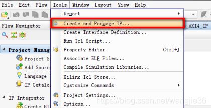
(1)打开vivado,选择菜单栏Tools > Create and Package IP
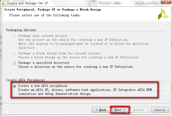
(2)其中Package a new IP for the Vivado IP Catalog就是我们自定义IP时采用的两种方式,即打包工程或打包文件夹。其中Create a new AXI4Peripheral就是创建AXI4外设IP,点击 Next。

(3)选择Create a new AXI4 peripheral,点击Next
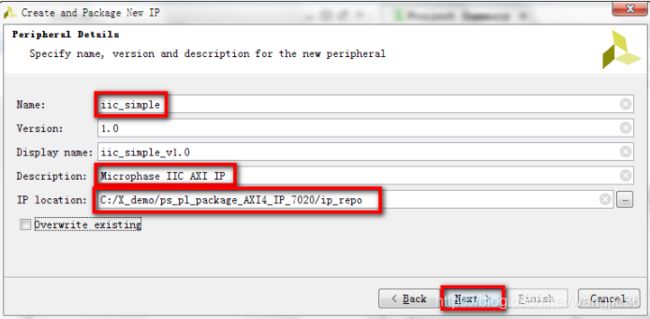
(4)填写要打包的AXI外设IP的信息。这里修改了Name名称,Description描述和打包存储的路径IP location。可以自行定义这些信息,点击Next。
(5),iic.v的模块头, AXI IP有7个寄存器要放在AXI总线上,所以如下的寄存器个数填为7,其它选项保持默认,点击Next。
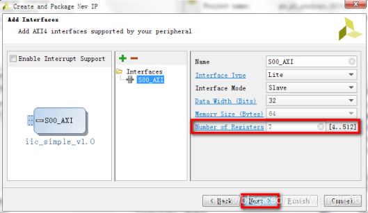
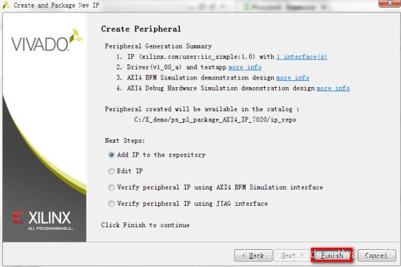
Summary窗口,选项保持默认值,点击 Finish 完成。
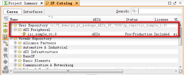
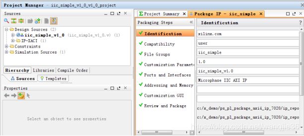
(6)下点击左侧边栏Project Manager底下的IP Catalog,打开IP列表窗口。在IP Catalog窗口,已经有了我们自定义的AXI IP;
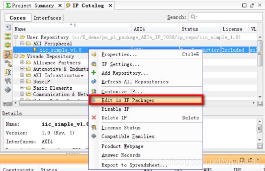
4,修改IP代码
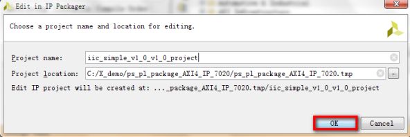
(1)右键单击iic_simple_v1.0选择Edit in IP Packager选项;
(2)如下弹窗点击OK,将打开一个临时的IP packager工程
在Source窗口,双击打开iic_simple_v1_0文件进行编辑,
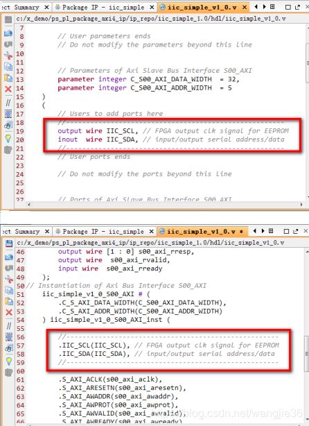
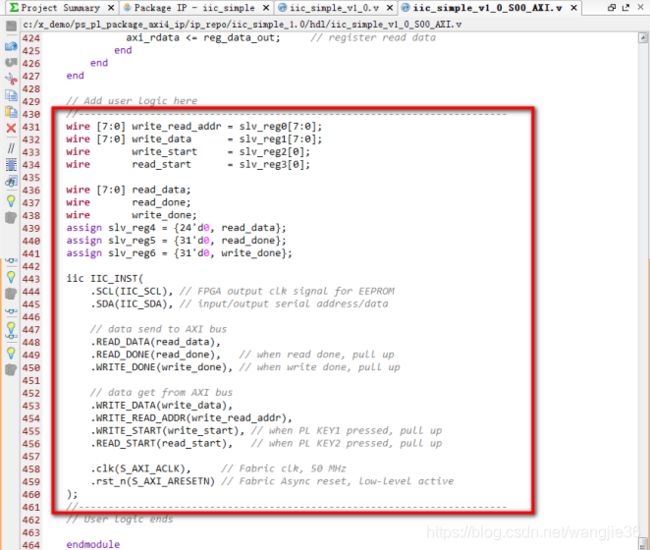
(3)增加 IIC 的端口列表,再增加例化列表,所示:
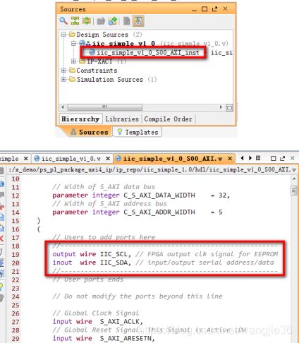
(4)在Source窗口,双击打开iic_simple_v1_0_S00_AXI_inst文件进行编辑,增加端口列表。
(5)再将7个register中的后三个改为wire型存储从AXI总线上读取的值,不对其进行设置
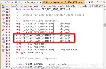
(6)然后例化IIC模块如下。其中slv_reg0,slv_reg1,slv_reg2,slv_reg3分别在SDK软件中设置读写地址,写数据,写开始,读开始信号,这些数据设置好之后送往 AXI 总线。slv_reg4,
slv_reg5,slv_reg6作为读数据,读完成,写完成的暂存位置,这些数据从AXI总线上获得,在SDK软件中进行处理。
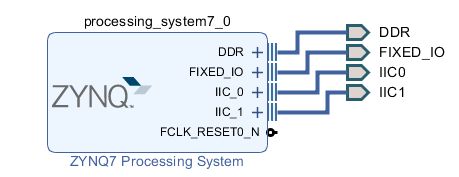
三,使用MIO或EMIO引出IIC接口
EEPROM 即电可擦除可编程只读存储器,是一种常用的非易失性存储器(掉电数据不丢失),EEPROM 有多种类型的产品,ATMEL 公司生产的 AT24C 系列的 AT24C64 这一型号。实验所用的 AT24C64 存储容量64Kbit,内部分成 256 页,每页 32 字节,共有 8192 个字节,且其读写操作都是以字节为基本单位。可以把 AT24C64 看作一本书,那么这本书有 256 页,每页有 32 行,每行有 8 个字,总共256*32*8=65536。
1,vivado搭建和配置读写AT24C64
(1)IIC_EEPROM.H
#ifndef SRC_DRIVER_IIC_EEPROM_H_
#define SRC_DRIVER_IIC_EEPROM_H_
#include "xparameters.h"
#include "xiicps.h"
#include "sleep.h"
#define EEPROM_IIC_DEVICE_ID		XPAR_XIICPS_0_DEVICE_ID
#define IIC_SLAVE_ADDR		0x50
#define IIC_SCLK_RATE		100000
#define EEPROM_PAGE_SIZE	16
#define REGION_PAGE_NUM 	16
#define REGION_SIZE			256
#define REGION_NUM			2
#define EEPROM_TOTAL_SIZE	(REGION_NUM * REGION_SIZE)
#define DEVICE_ID_ADDR_EEPROM		0x00
#define ZW_ID_ADDR_EEPROM			0x01
int Iic_Eeprom_Init(u16 DeviceId);
void Write_Eeprom_OneByte(u16 addr, u8 value);
u8 Read_Eeprom_OneByte(u16 addr);
void Write_Eeprom_4Byte(u16 addr, u32 value);
u32 Read_Eeprom_4Byte(u16 addr);
void Read_Eeprom_Bytes(u16 addr, u8 *recv_buffer, u16 len);
void Write_Eeprom_Page(u16 page_num, u8 *value);
int Eeprom_Erase();
#endif /* SRC_DRIVER_IIC_EEPROM_H_ */
(2)IIC_EEPROM.C
#include "iic_eeprom.h"
 XIicPs Iic;		/**< Instance of the IIC Device */
 u8 SendBuffer[EEPROM_PAGE_SIZE + 1];
 u8 RecvBuffer[EEPROM_PAGE_SIZE];
int Iic_Eeprom_Init(u16 DeviceId)
{
	int Status;
	XIicPs_Config *Config;
	/*
	 * Initialize the IIC driver so that it's ready to use
	 * Look up the configuration in the config table,
	 * then initialize it.
	 */
	Config = XIicPs_LookupConfig(DeviceId);
	if (NULL == Config)
    {
		return XST_FAILURE;
	}
	Status = XIicPs_CfgInitialize(&Iic, Config, Config->BaseAddress);
	if (Status != XST_SUCCESS) {
		return XST_FAILURE;
	}
	/*
	 * Perform a self-test to ensure that the hardware was built correctly.
	 */
	Status = XIicPs_SelfTest(&Iic);
	if (Status != XST_SUCCESS)
    {
		return XST_FAILURE;
	}
	XIicPs_SetSClk(&Iic, IIC_SCLK_RATE);
	return XST_SUCCESS;
}

int IicPs_Write(XIicPs *Iic_ptr, u8 *MsgPtr, u16 ByteCount, u8 SlaveAddr)
{
	int Status;
	/*
	 * Send the buffer using the IIC and ignore the number of bytes sent
	 * as the return value since we are using it in interrupt mode.
	 */
	Status = XIicPs_MasterSendPolled(Iic_ptr, MsgPtr,
			 ByteCount, SlaveAddr);
	if (Status != XST_SUCCESS) {
		return XST_FAILURE;
	}
	/*
	 * Wait until bus is idle to start another transfer.
	 */
	while (XIicPs_BusIsBusy(Iic_ptr)) {
		/* NOP */
	}
	return XST_SUCCESS;
}

int IicPs_Read(XIicPs *Iic_ptr, u8 *MsgPtr, u16 ByteCount, u8 SlaveAddr)
{
	int Status;
	/*
	 * Send the buffer using the IIC and ignore the number of bytes sent
	 * as the return value since we are using it in interrupt mode.
	 */
	Status = XIicPs_MasterRecvPolled(Iic_ptr, MsgPtr,
			  ByteCount, SlaveAddr);
	if (Status != XST_SUCCESS)
    {
		return XST_FAILURE;
	}
	/*
	 * Wait until bus is idle to start another transfer.
	 */
	while (XIicPs_BusIsBusy(Iic_ptr)) {
		/* NOP */
	}
	return XST_SUCCESS;
}

/*
 * EEPROM写入1字节函数
 *
 */
void Write_Eeprom_OneByte(u16 addr, u8 value)
{
	if(addr > EEPROM_TOTAL_SIZE - 1){
		return;
	}
	u8 SlaveAddr  = addr / REGION_SIZE + IIC_SLAVE_ADDR;		//计算EEPROM分区地址
	u8 write_addr = addr % REGION_SIZE;						//确定分区内实际的存储地址
	SendBuffer[0] = write_addr;
	SendBuffer[1] = value;
	IicPs_Write(&Iic, SendBuffer, 2, SlaveAddr);
}

/*
 * EEPROM读取1字节函数
 *
 */
u8 Read_Eeprom_OneByte(u16 addr)
{
	if(addr > EEPROM_TOTAL_SIZE - 1){
		return 0;
	}
	u8 value;
	u8 SlaveAddr  = addr / REGION_SIZE + IIC_SLAVE_ADDR;		//计算EEPROM分区地址
	u8 write_addr = addr % REGION_SIZE;						//确定分区内实际的存储地址
	SendBuffer[0] = write_addr;
	IicPs_Write(&Iic, SendBuffer, 1, SlaveAddr);
	IicPs_Read(&Iic, &value, 1, SlaveAddr);
	return value;
}
/*
 * EEPROM写入4字节函数
 *
 */
void Write_Eeprom_4Byte(u16 addr, u32 value)
{
	if(addr > EEPROM_TOTAL_SIZE - 4)
    {
		return;
	}
	u8 *v_ptr = (u8 *)&value;
	u8 SlaveAddr  = addr / REGION_SIZE + IIC_SLAVE_ADDR;		//计算EEPROM分区地址
	u8 write_addr = addr % REGION_SIZE;						//确定分区内实际的存储地址
	u8 write_len = 4;

	u8 remain_size = (u16)((write_addr / EEPROM_PAGE_SIZE + 1) * EEPROM_PAGE_SIZE) - write_addr;	//计算当前页剩余的大小
	if(remain_size >= 4){		//当前页空间足够,直接写入
		SendBuffer[0] = write_addr;
		memcpy(SendBuffer + 1, v_ptr, write_len);
		IicPs_Write(&Iic, SendBuffer, write_len + 1, SlaveAddr);
	}else{						//当前页空间不足,跨页写入
		SendBuffer[0] = write_addr;
		write_len = remain_size;
		memcpy(SendBuffer + 1, v_ptr, write_len);
		IicPs_Write(&Iic, SendBuffer, write_len + 1, SlaveAddr);

		usleep(3000);
	    if(REGION_SIZE - 4 < write_addr)
        {		//当前页空间不足且分区空间也不足,跨区写入
			SlaveAddr = SlaveAddr + 1;
		}
		SendBuffer[0] = (write_addr + remain_size) % REGION_SIZE;
		write_len = 4 - remain_size;
		memcpy(SendBuffer + 1, v_ptr + remain_size, write_len);
		IicPs_Write(&Iic, SendBuffer, write_len + 1, SlaveAddr);
	}

}

/*
 * EEPROM读取4字节函数
 *
 */
u32 Read_Eeprom_4Byte(u16 addr)
{
	if(addr > EEPROM_TOTAL_SIZE - 4)
   {
		return 0;
	}

	u8 SlaveAddr  = addr / REGION_SIZE + IIC_SLAVE_ADDR;
	u8 write_addr = addr % REGION_SIZE;
	u32 read_value = 0;
	u8 read_len = 4;

	if(REGION_SIZE - 4 < write_addr){		//跨区读取
		SendBuffer[0] = write_addr;
		read_len = REGION_SIZE - write_addr;
		IicPs_Write(&Iic, SendBuffer, 1, SlaveAddr);
		IicPs_Read(&Iic, RecvBuffer, read_len, SlaveAddr);

		SendBuffer[0] = 0;
		SlaveAddr = SlaveAddr + 1;
		IicPs_Write(&Iic, SendBuffer, 1, SlaveAddr);
		IicPs_Read(&Iic, RecvBuffer + read_len, 4 - read_len, SlaveAddr);
	}else{
		SendBuffer[0] = write_addr;
		IicPs_Write(&Iic, SendBuffer, 1, SlaveAddr);
		IicPs_Read(&Iic, RecvBuffer, read_len, SlaveAddr);
	}

    read_value |= RecvBuffer[3] << 24;
	read_value |= RecvBuffer[2] << 16;
	read_value |= RecvBuffer[1] << 8;
	read_value |= RecvBuffer[0];

	return read_value;
}

/*
 * EEPROM读取多字节函数
 *
 */
void Read_Eeprom_Bytes(u16 addr, u8 *recv_buffer, u16 len)
{
	if((len > EEPROM_TOTAL_SIZE) || addr > EEPROM_TOTAL_SIZE - len)
    {
		return;
	}

	u8 SlaveAddr  = addr / REGION_SIZE + IIC_SLAVE_ADDR;
	u8 write_addr = addr % REGION_SIZE;
	u16 read_len = len;

	if(REGION_SIZE - write_addr < len)
    {		//跨区读取
		SendBuffer[0] = write_addr;
		read_len = REGION_SIZE - write_addr;
		IicPs_Write(&Iic, SendBuffer, 1, SlaveAddr);
		IicPs_Read(&Iic, recv_buffer, read_len, SlaveAddr);

		SendBuffer[0] = 0;
		SlaveAddr = SlaveAddr + 1;
		IicPs_Write(&Iic, SendBuffer, 1, SlaveAddr);
		IicPs_Read(&Iic, recv_buffer + read_len, len - read_len, SlaveAddr);
	}else{
		SendBuffer[0] = write_addr;
		IicPs_Write(&Iic, SendBuffer, 1, SlaveAddr);
		IicPs_Read(&Iic, recv_buffer, read_len, SlaveAddr);
	}

}

/*
 * EEPROM按页写入函数
 *
 */
void Write_Eeprom_Page(u16 page_num, u8 *value)
{
	if(page_num > (EEPROM_TOTAL_SIZE / 16) || value == NULL)
    {
		return;
	}

	u8 SlaveAddr  = page_num / REGION_PAGE_NUM + IIC_SLAVE_ADDR;		//计算EEPROM分区地址
	u8 write_addr = (page_num % REGION_PAGE_NUM) * 16;						//确定页起始地址
	u8 write_len = EEPROM_PAGE_SIZE;

	SendBuffer[0] = write_addr;
	memcpy(SendBuffer + 1, value, write_len);
	IicPs_Write(&Iic, SendBuffer, write_len + 1, SlaveAddr);
}

/*
 * EEPROM全片擦除函数
 *
 */
int Eeprom_Erase()
{
	int status;
	u8 SlaveAddr;
	u8 write_addr;
	u8 erase_buffer[17] = {0, 0xFF, 0xFF, 0xFF, 0xFF, 0xFF, 0xFF, 0xFF,0xFF, 0xFF, 0xFF, 0xFF, 0xFF, 0xFF, 0xFF, 0xFF, 0xFF};

	for(int i = 0; i < REGION_NUM; i++){
		SlaveAddr = IIC_SLAVE_ADDR + i;
		for(int j = 0; j < REGION_PAGE_NUM; j++){
			write_addr = EEPROM_PAGE_SIZE * j;
			erase_buffer[0] = write_addr;
			status = IicPs_Write(&Iic, erase_buffer, 17, SlaveAddr);
			usleep(3000);
			if (status != XST_SUCCESS) {
				return XST_FAILURE;
			}
		}
	}
	return XST_SUCCESS;
}
(3)main数据读写 0x54
Iic_Eeprom_Init(EEPROM_IIC_DEVICE_ID);
int data1=Read_Eeprom_OneByte(DEVICE_ID_ADDR_EEPROM);
int data2 = Read_Eeprom_OneByte(TEST_ID_ADDR_EEPROM);
data=0x33;
Write_Eeprom_Page(0, data);
2,zynq petalinux rootfs配置iictool工具
(1)内核配置petalinux-config -c kernel
Device Drivers --> I2C support --> i2C Hardware Bus support --> Xilinx I2C Controller
(2)设备树配置
(3)根文件系统配置
filesystem Packages --> base --> i2c-tools --> i2c-tools
3,iictool使用命令
(1)查看某总线上所有 i2c adapter: 输入 i2cdetect -l
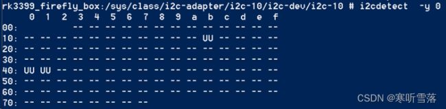
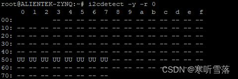
(2)罗列出每个 adapter 上设备地址的有效性: i2cdetect -y
标记UU 的,表示这个地址上有个设备是有效的。也就是当向这个地址发送询问时有应答。
这个例子中有三个地址是有效的,0x1b、0x40、0x41
(3)读取一个 7位地址 的器件的寄存器
> i2cget -f -y
> i2cget -f -y 0 0x40 0 (这个器件地址是0x40,读 0寄存器)
(4) 给 一个 7位地址 的器件中的寄存器 写值
> i2cset -f -y
> i2cset -y 0 0x50 0x00 0x10 (往0地址上写0x10)
(5)给一个 10位地址的器件写值 (驱动中是16位地址模式),这个命令只有在i2c-tools4.0之之后版本能输入。输入命令: i2ctransfer -y -f 0 w2@0x1d 0x00 0x20 r3
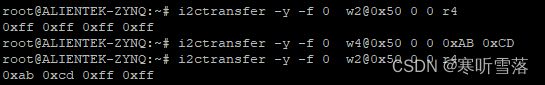
w2, 写入两字节,就是在数据线上要传输的字节数量
0x1d, 是器件地址,实际在总线上会发送 { 0x1d << 1 | [ 读写位 ] }
0x00 0x22, 共同组成0x0020这个寄存器的地址
r3,表示读3字节
> i2ctransfer -y -f 0 w4@0x1d 0x00 0x02 0x77 0x77
w4,表示数据线上传输4字节
0x00 0x02,表示寄存器地址
0x77, 第一个数据
0x77, 下一个地址上写
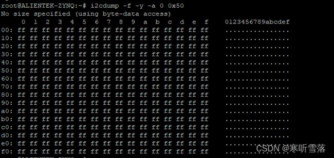
(6)i2cdump命令,其中0x50是设备地址
四,自己交叉编译iictool并放入板子上面使用
下载:
Index of /pub/software/utils/i2c-tools/
cd i2c-tools-4.2
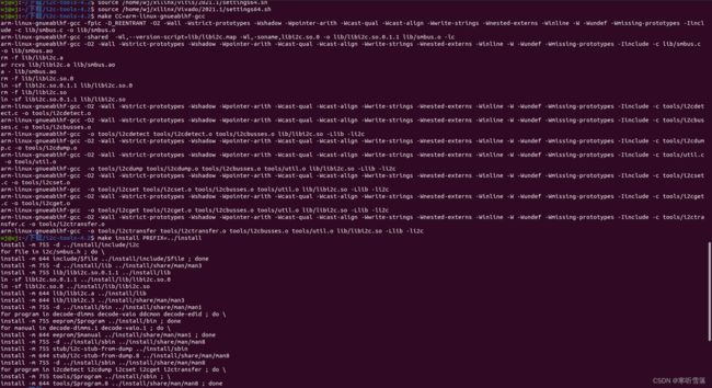
make CC=arm-linux-gnueabihf-gcc
i2c-tool/install/sbin$ ls
i2cdetect i2cdump i2cget i2cset i2c-stub-from-dump i2ctransfer

1,i2cdetect -r -y 4
0 1 2 3 4 5 6 7 8 9 a b c d e f
00: -- -- -- -- -- -- -- -- -- -- -- -- --
10: -- -- -- -- -- -- -- -- -- -- -- -- -- -- -- --
20: -- -- -- -- -- -- -- -- -- -- -- -- -- -- -- --
30: -- -- -- -- -- -- -- -- -- -- -- -- -- -- -- --
40: -- -- -- -- -- -- -- -- -- 49 -- -- -- -- -- --
50: -- -- -- -- -- -- -- -- -- -- -- -- -- -- -- --
60: -- -- -- -- -- -- -- -- -- -- -- -- -- -- -- --
2,i2cdump -f -y 1 0x68
i2cdump命令可以列出整个设备的内容。如果无法读取,则显示XX。
3,写入值到i2c上的设备寄存器
i2cset -y -f 0 0x50 0x00 0x11
# 0:i2c-0
# 0x50 : 设备地址
# 0x00 :寄存器偏移
# 0x11 :写入值
4,i2cget可以读取一个值
i2cget -f -y 1 0x68 0x3f
# 0x3f 由 0x30 上的 f 得到,对应上面dump结果的 最后一个有效值。
88
i2cget -f -y 1 0x68 0
# 同理,得到上面的第一个有效值 28