DSP 开发例程: uart_echo

此例程实现计算机与 EVM6678L 开发板之间的串口通信. 采用 串口接收中断的方式, 将计算机通过串口发送的字符发回计算机. 数据流图如下图所示:

DSP
TASK
UART
串口
串口
接收中断
发送信号量
中断服务进程
UART_RX
UART_TX
等待信号量
读串口数据
写串口数据
计算机

此例程使用了 SYS/BIOSMCSDK PDK TMS320CC6678 两个组件. 例程源码可从我的 gitee.com 仓库上克隆或下载.

目录

    • 新建工程
    • 源码编辑
      • app.cfg
      • uart.h
      • uart.c
      • main.c
    • 调试

新建工程

此实例工程直接在 led_flash 工程基础上修改.

  • 选中 led_flash 工程, 右键选择 Copy 或 使用快捷键 Ctrl+C 复制工程.

DSP 开发例程: uart_echo_第1张图片

  • 在工程浏览视图中, 右键选择 Paste 或使用快捷键 Ctrl+V 粘贴工程.

DSP 开发例程: uart_echo_第2张图片

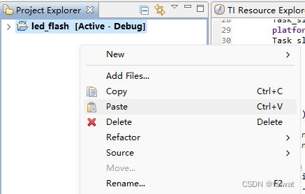
  • 在弹出的 Copy Project 对话框中 修改工程名为: uart_echo, 点击 OK.

DSP 开发例程: uart_echo_第3张图片

  • 删除 uart_echo 工程中的 Debug目录, 右键选择 Build Project, 编译此工程.

源码编辑

app.cfg

由于 串口接收中断 URXEVT 是次级中断(事件), 连接至 片上中断控制器(chip interrupt controller, CIC), 如下表所示.

Input Event# on CIC System Interrupt Description
148 UARTINT UART interrupt
149 URXEVT UART receive event
150 UTXEVT UART transmit event

参见: tms320c6678.pdf 中的 Table 7-39. 该文档可以在 C:\ti\pdk_C6678_1_1_2_6\docs 文件夹中找到.

因此, 需要启用 ti.sysbios.family.c66.tci66xx.CpIntc 组件.

  • 使用 XGCONF 打开 app.cfg 文件.
    DSP 开发例程: uart_echo_第4张图片
  • Available Products 面板中 的 SYS/BIOS | Target Specific Support | C66 树找到 CpIntc, 右键选择: Use CpIntc.

DSP 开发例程: uart_echo_第5张图片
或者直接在 app.cfg 中输入:

var CpIntc = xdc.useModule('ti.sysbios.family.c66.tci66xx.CpIntc');

uart.h

新建 uart.h 头文件. 内容如下:

#ifndef UART_H_
#define UART_H_

#include 

#include 
#include 

/**
 * UART Receive ISR
 */
void isr_uart_recv(UArg arg);

/**
 * Task for UART Echo
 *
 * \param a0 not used.
 * \param a1 not used.
 */
void task_uart_echo(UArg a0, UArg a1);


#endif /* UART_H_ */

其中,

  • isr_uart_recv() 为 串口接收中断服务进程. 用于接收串口数据, 发送信号量给 task_uart_echo().
  • task_uart_echo() 为串口数据回显任务. 等待 isr_uart_recv() 发送的信号量, 并发送串口数据.

uart.c

新建 uart.c源文件, 文件内容如下:

#include 
#include 

#include 
#include 

#include 

#include "uart.h"

Semaphore_Handle semUartRecv;

uint8_t uartRecvBuf[256];

static void uart_recvIntEnable()
{
	CSL_UartRegs *uartRegs = (CSL_UartRegs *)CSL_UART_REGS;
  // ?? FCR_DMAMODE1 必须使能, 不然收不到中断
	CSL_FINS(uartRegs->FCR, UART_FCR_DMAMODE1, CSL_UART_FCR_DMAMODE1_ENABLE);

	//enable receive interrupts
	CSL_FINS(uartRegs->LCR, UART_LCR_DLAB, CSL_UART_LCR_DLAB_DISABLE);
	CSL_FINS(uartRegs->IER, UART_IER_ELSI, CSL_UART_IER_ELSI_ENABLE);
	CSL_FINS(uartRegs->IER, UART_IER_ERBI, CSL_UART_IER_ERBI_ENABLE);
}


void isr_uart_recv(UArg arg)
{
	Semaphore_post(semUartRecv);
}

void task_uart_echo(UArg a0, UArg a1)
{
	Platform_STATUS status;
	Error_Block eb;
	uint32_t uartRecvLen = 0;
	uint8_t ch;
	System_printf("enter task_uart_echo()\n");
	System_printf("Create semUartRecv\n");
	semUartRecv = Semaphore_create(0, NULL, &eb);
	if (semUartRecv == NULL)
	{
		System_printf("Semaphore_create() failed!\n");
		BIOS_exit(0);
	}

	System_printf("UART receive interrupts enable.\n");
	uart_recvIntEnable();

	while(1)
	{
		Semaphore_pend(semUartRecv, BIOS_WAIT_FOREVER);
		while(1)
		{
			status = platform_uart_read(&ch, 1);
			if (status == Platform_EOK)
			{
				platform_uart_write(ch);
				switch(ch)
				{
				case '\r': // 回车
					uartRecvBuf[uartRecvLen] = '\0';
					System_printf("UART received: %s\n", uartRecvBuf);
					uartRecvLen = 0;
					break;
				case 0x08: // 退格
					if(uartRecvLen > 0)
						uartRecvLen--;
					break;
				default:
					if (uartRecvLen < 255)
					{
						uartRecvBuf[uartRecvLen++] = ch;
					}
					else
					{
						System_printf("UART received buffer full!");
						uartRecvLen = 0;
					}
				}
			}
			else
			{
				break;
			}
		}
	}
}

main.c

修改 main.c 源文件, 内容如下:

/*
 *  ======== main.c ========
 */
#include 
#include 

#include 

#include 
#include 

#include 
#include 
#include 
#include 


#include 

#include "uart.h"


void isr_register()
{
	Int eventId;
	Hwi_Params params;
	Error_Block eb;
	UInt sysInt = CSL_INTC0_URXEVT;
	UInt hostInt = 8;
	Int intNum = 7;

	// Map system interrupt #CSL_INTC0_URXEVT to host interrupt 8 on Intc 0
	CpIntc_mapSysIntToHostInt(0, sysInt, hostInt);

	// Plug the function and argument for System interrupt #CSL_INTC0_URXEVT then enable it
	CpIntc_dispatchPlug(sysInt, isr_uart_recv, sysInt, TRUE);

	// Enable Host interrupt 8 on Intc 0
	CpIntc_enableHostInt(0, hostInt);
	// Enable system interrupt #CSL_INTC0_URXEVT
	CpIntc_enableSysInt(0, sysInt);

	// Get the eventId associated with Host interrupt 8
	eventId = CpIntc_getEventId(hostInt);

	// Initialize the Hwi parameters
	Hwi_Params_init(&params);
	// Set the eventId associated with the Host Interrupt
	params.eventId = eventId;
	// The arg must be set to the Host interrupt
	params.arg = hostInt;
	// Enable the interrupt vector
	params.enableInt = TRUE;

	// Initialize the error block
	Error_init(&eb);

	System_printf("Hwi_create(%d, &CpIntc_dispatch)\n", intNum);
	// Create the Hwi on interrupt 7 then specify 'CpIntc_dispatch'
	// as the function.
	Hwi_create(intNum, &CpIntc_dispatch, &params, &eb);
}


/**
 * 平台初始化
 */
void EVM_init()
{
	platform_init_flags init_flags;
	platform_init_config init_config;

	// plaform initialize
	memset(&init_flags, 1, sizeof(platform_init_flags));
	init_flags.phy = 0;
	memset(&init_config, 0, sizeof(platform_init_config));
	if (platform_init(&init_flags, &init_config) != Platform_EOK)
	{
		printf("Platform failed to initialize, errno = 0x%x \n", platform_errno);
		while(1);
	}
	// UART Initialize...
	// set baudrate to 115200.
	platform_uart_init();
}

/*
 *  ======== main ========
 */
Int main()
{ 
    Task_Handle task;
    Error_Block eb;

    System_printf("enter main()\n");

    isr_register();

    Error_init(&eb);
    task = Task_create(task_uart_echo, NULL, &eb);
    if (task == NULL) {
        System_printf("Task_create() failed!\n");
        BIOS_exit(0);
    }

    BIOS_start();    /* does not return */
    return(0);
}

其中,

  • EVM_init() 函数中调用了 串口初始化函数 platform_uart_init();
  • isr_register() 函数完成 Hwi 进程的创建, 中断服务进程的注册, System InterruptHost Interrupt 之间的映射. 有关 CpIntc 模块的使用方法, 后续再单独讲解.

调试

完成编译后, 在 EVM6678L 上调试.

串口通过USB连接计算机. 请确保 COM_SEL1 跳线设置在正确位置. 且在计算机设备管理器中能够找到对应板卡的串口.

DSP 开发例程: uart_echo_第6张图片

打开串口终端, 连接对应串口, 串口设置如下:

DSP 开发例程: uart_echo_第7张图片

如果在终端中输入一段字符串, 终端能够正常回显. 暂停运行后, 在 RTOS Object View(ROV)SysMinOutputBuffer 可以看到通过终端发送的字符串, 说明程序工作正常.
DSP 开发例程: uart_echo_第8张图片

你可能感兴趣的:(DSP,DSP)