【原创】The solutional manual of the Verilog HDL: A Guide to Digital Design and Synthesis (2nd)--ch06
Chapter 6. Dataflow Modeling
6.7 Exercises
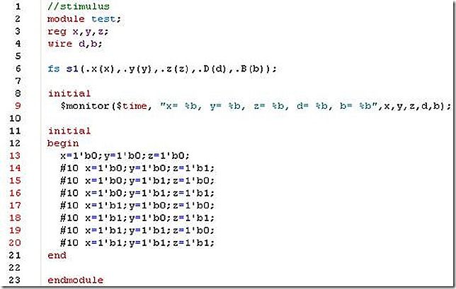
1. A full subtractor has three 1-bit inputs x,y,and z(previous borrow) and two 1-bit outputs D(difference) and B(borrow). The logic equations for D and B are as follows:
D=x’.y’.z + x’.y.z’ + x.y’.z’ + x.y.z
B=x’.y + x’.z + y.z
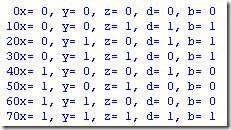
Write the full Verilog description for the substractor module, including I/O ports (Remember that + in logic equations corresponds to a logical or operator (||) in dataflow). Instantiate the subtractor inside a stimulus block and test all eight possible combinations of x,y,and z given in the following truth table.
| X |
Y |
Z |
B |
D |
| 0 |
0 |
0 |
0 |
0 |
| 0 |
0 |
1 |
1 |
1 |
| 0 |
1 |
0 |
1 |
1 |
| 0 |
1 |
1 |
1 |
0 |
| 1 |
0 |
0 |
0 |
1 |
| 1 |
0 |
1 |
0 |
0 |
| 1 |
1 |
0 |
0 |
0 |
| 1 |
1 |
1 |
1 |
1 |
my answer:
2. A magnitude comparator checks if one number is greater than or equal to or less than another number. A 4-bit magnitude comparator takes two 4-bit numbers, A and B, as input. We write the bits in A and B as follows. The leftmost bit is the most significant bit.
A=A(3)A(2)A(1)A(0)
B=B(3)B(2)B(1)B(0)
The magnitude can be compared by comparing the numbers bit by bit, starting with the most significant bit. If any bit mismatches, the number with bit 0 is the lower number. To realize this functionality in logic equations, let us define an intermediate variable. Notice that the function below is an xnor function.
x(i)=A(i)B(i)+A(i)’B(i)’
The three outputs of the magnitude comparator are A_gt_B,A_lt_B,A_eq_B. They are define with the following logic equations:
A_gt_B=A(3)B(3)’ + x(3).A(2).B(2)' + x(3).x(2).A(1).B(1)' + x(3).x(2).x(1).A(0).B(0)'
A_lt_B = A(3)'.B(3) + x(3).A(2)'.B(2) + x(3).x(2).A(1)'.B(1) + x(3).x(2).x(1).A(0)'.B(0)
A_eq_B = x(3).x(2).x(1).x(0)
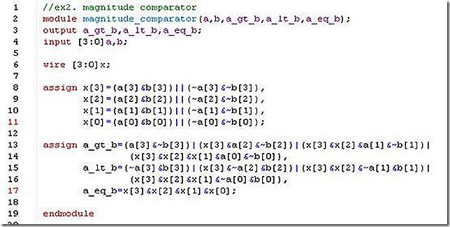
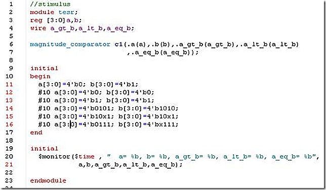
Write the Verilog description of the module magnitude_comparator. Instantiate the magnitude comparator inside the stimulus module and try out a few combinations of A and B.
my answer:
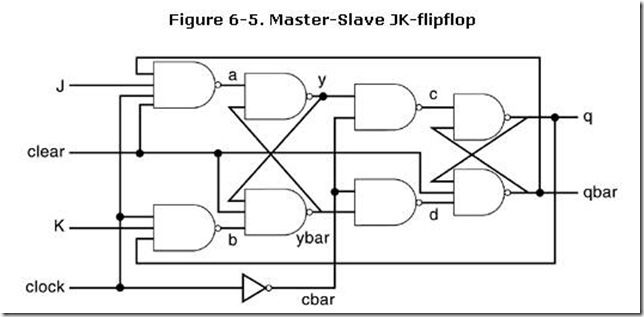
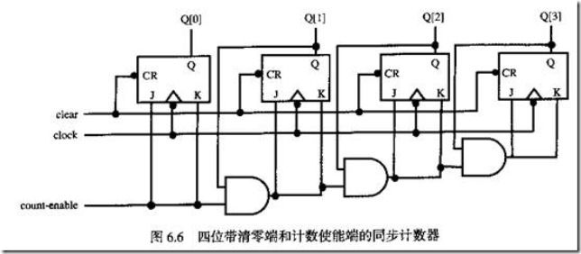
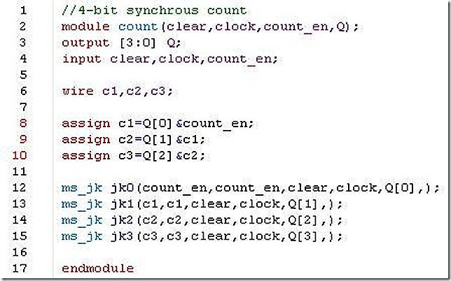
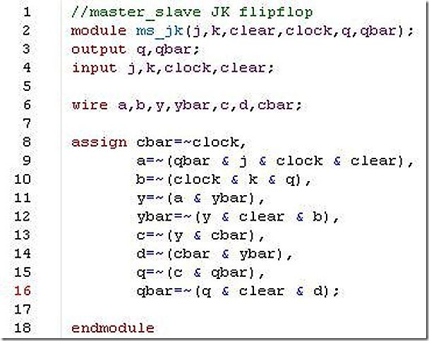
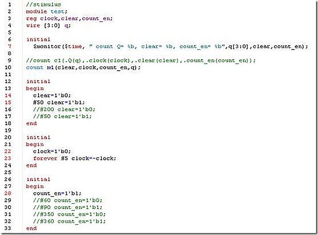
3. A synchronous counter can be designed by using master-slave JK flipflops. Design a 4-bit synchronous counter. Circuit diagrams for the synchronous counter and the JK flipflop are given below. The clear signal is active low. Data gets latched on the positive edge of clock, and the output of the flipflop appears on the negative edge of clock. Counting is disabled when count_enable signal is low. Write the dataflow description for the synchronous counter. Write a stimulus file that exercises clear and count_enable. Display the output count Q[3:0].
my answer:
(ps:图6.6有 错误J)
Reference
Smair Palnitkar, <Verilog HDL: A Guide to Digital Design and Synthesis (2nd) >

