Cordic IP核使用说明以及避坑记录
Cordic IP核使用说明以及避坑记录
参考文章:(140条消息) Vivado cordic IP核rotate和translate使用详解(附有代码)_cordic ip核 rotate_迎风打盹儿的博客-CSDN博客
(140条消息) VIVADO cordic IP核_卡布奇诺加勺糖的博客-CSDN博客
文章目录
- Cordic IP核使用说明以及避坑记录
- 前言
- 一、cordic算法的原理
- 二、cordic IP核主要功能:
-
- 1.translate模式IP核配置和踩坑记录
- 2. rotate模式IP核配置和踩坑记录
- 3. 代码参考
前言
项目需求使用了cordicIP核取相位然后旋转,这篇文章主要是记录一下学习IP核以及使用IP核过程中遇到的问题。
一、cordic算法的原理
推荐学习视频:FPGA:Cordic算法介绍与实现_哔哩哔哩_bilibili
视频清晰的讲述了cordic算法的原理以及硬件实现,视频下方还提供了代码和资料,其中有一份XILINX-CORDIC算法文档非常推荐一看。
二、cordic IP核主要功能:
CORDIC(Coordinate Rotation Digital Computer)算法即坐标旋转数字计算方法。该算法通过基本的加和移位运算代替乘法运算,使得矢量的旋转和定向的计算不再需要三角函数、乘法、开方、反三角、指数等函数。有以下功能模式:
- rotate 旋转
- translate 变换 ——直角坐标转极坐标
- sin/cos
- arctan
- sinh/cosh
- arc tanh
- square root 平方根
这次实现主要关注的是:rotate、 translate
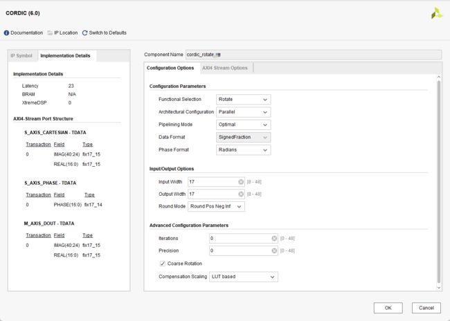
1.translate模式IP核配置和踩坑记录

- Functional Selection: 模式选择,此处选择Translate
- Architectural Configuration: CORDIC核心有两种架构配置,并行和串行。
- Pipelining Mode: CORDIC核心提供了三种流水线模式:无、最优和最大。流水线模式的选择基于功能配置和体系结构配置的选择。
None: CORDIC核心在没有流水线的情况下实现。
优化: CORDIC核心实现了尽可能多的流水线阶段,而不使用任何额外的lut。 最大:CORDIC核心在每个shift-add子阶段之后都有一个管道实现。 此处选择优化。
- Phase Format:
radians格式下就是输入正常的弧度制,输入范围是(-π,π) scale
radians则是输入归一化的弧度值,输入范围是(-1,1) 说明白点,radians格式下,你的输入就相当于在scale radians下输入再乘π。 此处选择Radians。
- Round Mode: CORDIC核心提供四种舍入模式。
Truncate截断: The X_OUT, Y_OUT, and PHASE_OUT outputs are truncated.
Positive Infinity向上取整: The X_OUT, Y_OUT, and PHASE_OUT outputs are
rounded such that 1/2 is rounded up (towards positive infinity). It is
equivalent to the MATLAB function floor(x + 0.5).
Pos Neg Infinity四舍五入: The outputs X_OUT, Y_OUT, and PHASE_OUT are rounded such that 1/2 is rounded up (towards positive infinity) and -1/2 is rounded down (towards negative infinity). It is equivalent to the MATLAB function round(x).
Nearest Even最近偶数: The X_OUT, Y_OUT, and PHASE_OUT outputs are rounded toward the nearest even number such that a 1/2 is rounded down and 3/2 is rounded up.
根据需要选择Round Pos Neg Inf。
- Iterations和 Precision: 不选设为0 IP核根据其他设置默认设置。
- Coarse Rotation:如果关闭粗旋转,输入/输出范围将限制在第一象限(-Pi/4,+ Pi/4)。所以应该勾上。
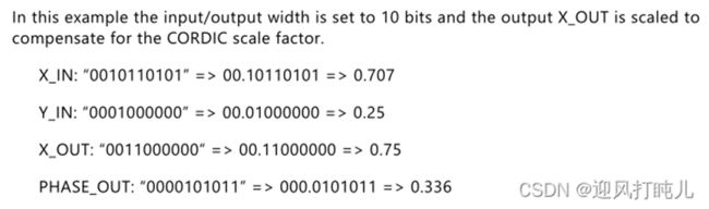
- 【坑】Compensation Scaling:补偿方式。cordic这个IP核在使用的时候他的输出是乘了倍数Z的,第一次用的时候没有勾选补偿方式,发现输出结果角度是对的,但是模值不正确,
勾选补偿方式后cordic会自己把输出再乘一个Z的倒数,这样就对了。
No Scale Compensation: 输出X和Y没有补偿,并生成,按比例Z缩放。
LUT Based:输出X和Y补偿使用基于LUT的常系数乘法器。
BRAM: 输出X和Y使用块ram为基础的常系数乘法器进行补偿。
Embedded Multiplier: 输出X和Y使用DSP Slice进行补偿。
此处如果选No,不会补偿,输出结果不对。以保证结果正确,必须选择一项补偿方式。此处默认选LUT Based。
-
数据范围 需要注意,否则输出可能出错

Translation的数据范围,fix格式下数据范围不能超过±1,此外要注意输出的模值会不会超位宽的问题,如果有超需要扩展位宽!!!。Fix16_14实际上就是(signed [15:0])/2^14。Fix16_14: 1(符号位)+1(整数位)+14(小数位)
仿真器显示定点小数:
【技巧】Vivado 仿真器simulation显示定点小数_LiangWF22的博客-CSDN博客

-
输入PADDING:具体是否有补零和补零位数根据IP核配置页面为准。另外如果输入X/Y_IN位宽和IP核位宽不一致需要补符号位。

第二页不用修改使用默认值即可:

2. rotate模式IP核配置和踩坑记录
配置和translate模式基本一致,这里我采的一个坑是,我是把translate的输出模值和相位经过一定处理后送到rotate里面,translate的输出位宽是16位,相位是fix16_13,但是我的rotate的输入phase是fix17_14(为了避免rotate输出的模值溢出多给了一位)我刚开始是直接补的符号位,这样子==实际上rotate收到的phase变成原来的一半了!!!==导致一个数据也不对,后来改成低位补一个0就解决了。
3. 代码参考
参考: (140条消息) Vivado cordic IP核rotate和translate使用详解(附有代码)_cordic ip核 rotate_迎风打盹儿的博客-CSDN博客
1.	`timescale 1ns / 1ps
2.
3.
4.	module cordic_test_tb();
5.
6.	// cordic_translate_test Parameters
7.	parameter PERIOD  = 2;
8.
9.	// cordic_translate_test Inputs
10.	reg   clk                                  = 0 ;
11.	reg   start                                = 0 ;
12.	reg   [15:0]  x_in                         = 0 ;
13.	reg   [15:0]  y_in                         = 0 ;
14.	reg   [15:0]  pha_in                       = 0 ;
15.
16.	// cordic_translate_test Outputs
17.	wire  over1                                 ;
18.	wire  over2                                 ;
19.	wire  [15:0]  x_out1                        ;
20.	wire  [16:0]  x_out2                        ;
21.	wire  [16:0]  y_out2                        ;
22.	wire  [15:0]  pha_out                      ;
23.
28.
29.	cordic_translate_test  u_cordic_translate_test (
30.	    .clk                     ( clk             ),
31.	    .start                   ( start           ),
32.	    .x_in                    ( x_in     [15:0] ),
33.	    .y_in                    ( y_in     [15:0] ),
34.
35.	    .over                    ( over1            ),
36.	    .x_out                   ( x_out1    [15:0] ),
37.	    .pha_out                 ( pha_out   [15:0] )
38.	);
39.
40.
41.	initial
42.	begin
43.		forever #(PERIOD/2)  clk=~clk;
44.	    #5  start<=1;
45.	    x_in<=16'b0011000000000000;
46.	    y_in<=16'b0011000000000000;
47.	    pha_in<=16'b0011001001000011;
48.	    #2
49.	    x_in<=16'b1110000000000000;
50.	    y_in<=16'b1110000000000000;
51.	    pha_in<=16'b1001101101111000;
52.
53.	    #10
54.	    x_in<=16'b0110000000000000;
55.	    y_in<=16'b1010000000000000;
56.	    pha_in<=16'b0110010010000111;
57.	end
58.
59.
60.
61.	cordic_rotate_test  u_cordic_rotate_test (
62.	    .clk                     ( clk            ),
63.	    .start                   ( start          ),
64.	    .x_in                    ( x_in           ),
65.	    .y_in                    ( y_in           ),
66.	    .pha_in                  ( pha_in         ),
67.
68.	    .over                    ( over2           ),
69.	    .x_out                   ( x_out2          ),
70.	    .y_out                   ( y_out2          )
71.	);
72.
73.
74.
75.
76.	endmodule
module cordic_rotate_test(
input clk,                    //输入时钟信号
input start,                  //输入开始计算信号
input [15:0] x_in,            //输入坐标x
input [15:0] y_in,            //输入坐标y
input [15:0] pha_in,          //输入相角
output wire over,             //输出计算完成标志
output wire [16:0] x_out,     //输出坐标x
output wire [16:0] y_out      //输出坐标y
    );
wire [16:0]phase ;
wire [40:0] rotate_out;
//assign phase = {pha_in[15],pha_in};
assign phase = {pha_in,1'b0};
wire [16:0] x_in_1;
wire [16:0] y_in_1;
assign y_in_1 = {y_in[15],y_in};
assign x_in_1 = {x_in[15],x_in};
cordic_rotate u_cordic_rotate_ip (
  .aclk(clk),                                        // input wire aclk
  .s_axis_phase_tvalid(start),          // input wire s_axis_phase_tvalid
  .s_axis_phase_tdata(phase),            // input wire [17 : 0] s_axis_phase_tdata
  .s_axis_cartesian_tvalid(start),  // input wire s_axis_cartesian_tvalid
  .s_axis_cartesian_tdata({y_in_1,7'b0000000,x_in_1}),    // input wire [41 : 0] s_axis_cartesian_tdata
  .m_axis_dout_tvalid(over),            // output wire m_axis_dout_tvalid
  .m_axis_dout_tdata(rotate_out)              // output wire [41 : 0] m_axis_dout_tdata
);
assign  x_out = rotate_out[16:0];
assign  y_out = rotate_out[40:24];
endmodule
module cordic_translate_test(
input clk,                    //输入时钟信号
input start,                  //输入开始计算信号
input [15:0] x_in,            //输入坐标x
input [15:0] y_in,            //输入坐标y
output wire over,              //输出计算完成标志
output wire [15:0] x_out,      //输出坐标x
output wire [15:0] pha_out     //输出相角
);


cordic_translate cordic_translate_inst(
  .aclk(clk),                                        // input wire aclk
  .s_axis_cartesian_tvalid(start),  // input wire s_axis_cartesian_tvalid
  .s_axis_cartesian_tdata({y_in,x_in}),    // input wire [63 : 0] s_axis_cartesian_tdata
  .m_axis_dout_tvalid(over),            // output wire m_axis_dout_tvalid
  .m_axis_dout_tdata({pha_out,x_out})              // output wire [63 : 0] m_axis_dout_tdata

);

endmodule