urdf文件<gazebo>标签官方解释
Gazebo - Docs: Sensors (gazebosim.org)
Sensors
Note: This tutorial is a continuation from the Moving the robot tutorial.
In this tutorial we will learn how to add sensors to our robot and to other models in our world. We will use three different sensors: an IMU sensor, a Contact sensor and a Lidar sensor. We will also learn how to launch multiple tasks with just one file using gz launch.
You can find the final world of this tutorial here
IMU sensor
The inertial measurement unit (IMU) outputs the orientation of our robot in quaternions, the angular_velocity (角速度)in the three axes (X, Y, Z), and the linear_acceleration in the three axes. Let's use our moving_robot.sdf world and modify it. Create a new file sensor_tutorial.sdf and add the code from moving_robot.sdf to it. To define the IMU sensor add this code under the
plugin是插件的意思,在urdf文件里面的plugin放在gazebo标签内,用于添加插件
This code defines the IMU sensor plugin to be used in our world. Now we can add the IMU sensor to our robot as follows:(如果不添加
            0.001
            1.0


            true
            0 0 10 0 0 0
            0.8 0.8 0.8 1
            0.2 0.2 0.2 1

                1000
                0.9
                0.01
                0.001

            -0.5 0.1 -0.9


            true


                    0 0 1


                    0 0 1
                    100 100


                    0.8 0.8 0.8 1
                    0.8 0.8 0.8 1
                    0.8 0.8 0.8 1
    1
    1
    true
    imu
The sensor is usually added to one of the links of our model; we added it under the chassis link.
例如
Let's describe the tags:
Note: Not all the tags are supported for all sensors yet.
不是上面每个标签都可以用在所有的所有的标签内,就是说在雷达里面摄像头的某些标签不起作用,反过来也是一样的
Read data from IMU
To read the data from the IMU, run the world in one terminal and press the play button:(注意要按播放按钮)
gz sim sensor_tutorial.sdf
In another terminal, run:
gz topic -e -t /imu
The last command listens to the messages sent over the /imu topic. The IMU data are orientation, angular_velocity and linear_acceleration as described above. It should look like this:

Move your robot forward using the keyboard up key. You should see the sensor values changing.
Contact sensor不是通讯录传感器,是接触传感器
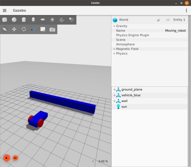
Let's introduce a different type of sensor, the contact sensor. You can guess from the name that this sensor gives indication when it touches (contacts) something else. We will build an obstacle (wall) and add the contact sensor to it. If the robot hits the obstacle it will stop, preventing the robot from damaging itself. Let's first build the obstacle as follows:
这个是一个gazebo里面的一堵墙的代码
    true
    5 0 0 0 0 0


                    0.5 10.0 2.0


                0.0 0.0 1.0 1
                0.0 0.0 1.0 1
                0.0 0.0 1.0 1


                    0.5 10.0 2.0
It is just a simple model with one link of box shape. You can check the Build your own robot tutorial to learn how to build models.
Now run the world and make sure that the wall appears in the simulation like this:
Let's add the contact sensor to the wall. As with the IMU sensor, we should first define the Contact sensor by adding the following code:就像IMU 那个搞法类似,我们先添加一个plugin
Now we can add the contact sensor to the box link of the wall model:
collision
The definition of the name and the type of the sensor. And inside the collision we define the box link collision name which is collision.
We need also to add the TouchPlugin under the wall model as follows:
vehicle_blue
wall
true
The TouchPlugin will publish (send) a message when the wall has been touched. The tags of the plugin are as follows:
vehicle_blue./wall/touchedtopic.
Run the world in one terminal:
gz sim sensor_tutorial.sdf
In another terminal, listen to the /wall/touched topic:
gz topic -e -t /wall/touched
Drive your robot forward to the wall using the keyboard arrow keys. Make sure to start the simulation by hitting the play button, and enable the Key Publisher plugin as well by clicking on the plugins dropdown list (vertical ellipsis), then selecting "Key Publisher".
When you hit the bump you should see a message data: true on the terminal where you ran the gz topic -e -t /wall/touched.
Now we can use the TriggeredPublisher plugin to make our robot stop when hits the wall as follows:
data: true
As explained in the Moving robot tutorial, we can publish an output depending on a received input. So when we receive data: true on the /wall/touched topic we publish linear: {x: 0.0}, angular: {z: 0.0} to make our robot stop.
Lidar sensor
We don't want our robot to touch the wall at all because this may cause some damage, so instead of the contact sensor we can use the Lidar. Lidar is an acronym for "light detection and ranging". This sensor can help us detect obstacles around the robot. We will use it to measure the distance between our robot and the wall.
First let's create a frame to fix our lidar to. This should be added inside of the vehicle_blue chassis:
0.8 0 0.5 0 0 0
Then add this plugin under the lidar sensor:
ogre2
Under the chassis link we can add the lidar sensor as follows:
"
    0 0 0 0 0 0
    lidar
    10


                640
                1
                -1.396263
                1.396263


                1
                0.01
                0
                0


            0.08
            10.0
            0.01


    1
    true
- First we defined the
nameandtypeof our sensor, then we defined itslidar_frame. - In the
lidardata is generated, in our case10 Hzwhich is equal to0.1 sec.- Under the
- The
- Under the
- The
Now run the world and press the play button in the bottom-left corner:
gz sim sensor_tutorial.sdf
Look at the lidar messages on the /lidar topic, specifically the ranges data:
gz topic -e -t /lidar
The lidar message has the following attributes:
message LaserScan
{
  Header header              = 1;

  string frame               = 2;
  Pose world_pose            = 3;
  double angle_min           = 4;
  double angle_max           = 5;
  double angle_step          = 6;
  double range_min           = 7;
  double range_max           = 8;
  uint32 count               = 9;
  double vertical_angle_min  = 10;
  double vertical_angle_max  = 11;
  double vertical_angle_step = 12;
  uint32 vertical_count      = 13;

  repeated double ranges              = 14;
  repeated double intensities         = 15;
}
Avoid the wall
Now as we have the lidar on our robot, we can use the ranges data and make our robot avoid hitting the wall. To do that, we'll write a short C++ program that listens to the sensor data and sends velocity commands to the robot. This program is called a node. We will build a node that subscribes to the /lidar topic and reads its data. Have a look at this tutorial to learn how to build a publisher and a subscriber node. You can download the finished node for this demo from here.
The lidar_node
gz::transport::Node node;
std::string topic_pub = "/cmd_vel";
gz::msgs::Twist data;
auto pub = node.Advertise(topic_pub);
We declare a node which will publish to cmd_vel topic and defined the message type Twist. Then advertise our node.
void cb(const gz::msgs::LaserScan &_msg)
{
  bool allMore = true;
  for (int i = 0; i < _msg.ranges_size(); i++)
  {
    if (_msg.ranges(i) < 1.0)
    {
      allMore = false;
      break;
    }
  }
  if (allMore) //if all bigger than one
  {
    data.mutable_linear()->set_x(0.5);
    data.mutable_angular()->set_z(0.0);
  }
  else
  {
    data.mutable_linear()->set_x(0.0);
    data.mutable_angular()->set_z(0.5);
  }
  pub.Publish(data);
}
Inside the callback function we check if the range of all rays are bigger than 1.0. If so we publish a message to our car to move forward. Otherwise we make the robot rotate.
int main(int argc, char **argv)
{
    std::string topic = "/lidar";
    // Subscribe to a topic by registering a callback.
    if (!node.Subscribe(topic, cb))
    {
        std::cerr << "Error subscribing to topic [" << topic << "]" << std::endl;
        return -1;
    }

    // Zzzzzz.
    gz::transport::waitForShutdown();

    return 0;
}
Inside the main we subscribe to the lidar topic, and wait until the node is shut down.
Build the node
Download the CMakeLists.txt, and in the same folder of lidar_node create build/ directory:
mkdir build
cd build
Run cmake and build the code:
cmake ..
make lidar_node
Run the node
Run the node from terminal 1:
./build/lidar_nodeRun the world from terminal 2:
gz sim sensor_tutorial.sdfNow you can see the robot move forward and as it approaches the wall it starts to turn left until it's clear and moves forward again (be sure to press the play button in the bottom-left corner to make the robot start moving).
Gazebo launch
Instead of running two different tasks from two different terminals we can make a launch file which will run the sensor_world and the lidar_node at the same time. Open your text editor and add the following code.
    gz sim sensor_tutorial.sdf


    ./build/lidar_node
The launch file is an XML file. We simply define what commands will run under the gz sim sensor_tutorial.sdf which launches the world. And the second command is ./build/lidar_node which runs the lidar_node. Save the file as sensor_launch.gzlaunch, and then run it using the following command:
gz launch sensor_launch.gzlaunchPress the play button to start the simulation. Hurray! Our robot is now moving and avoiding the wall.
To add even more complexity to your simulation, learn how to add actors to a world in the next tutorial.
Video walk-through
A video walk-through of this tutorial is available from our YouTube channel: Gazebo tutorials: Sensors