大型园区网建设(防火墙部分)
三、防火墙部分
1、FW1,FW2部署双机热备实现负载分担,并启用会话快速备份功能,解决来回路径不一致的问题,使用ip-link技术检测R1的loopback 0接口不可达则触发主备切换
[FW1-zone-dmz]di th
firewall zone dmz
 set priority 50
 add interface GigabitEthernet1/0/2
#

interface GigabitEthernet1/0/2
 ip address 172.16.245.12 255.255.255.0
#


HRP_M[FW1]dis cu | in hrp
 hrp enable
 hrp interface GigabitEthernet1/0/2 remote 172.16.245.13
 hrp mirror session enable
[FW2-zone-dmz]di th
firewall zone dmz
 set priority 50
 add interface GigabitEthernet1/0/2
#

interface GigabitEthernet1/0/2
 ip address 172.16.245.13 255.255.255.0
#

HRP_S[FW2]dis cu | in hrp
 hrp enable
 hrp interface GigabitEthernet1/0/2 remote 172.16.245.12
 hrp mirror session enable

#开启备用设备的部分配置功能
hrp standby config enable
#
配置安全策略,放行防火墙自身向外发送的包
HRP_M[FW1-policy-security]di th
security-policy
 rule name local_any
  source-zone local
  action permit
#
ip-link:
HRP_M[FW1]ip-link check enable
HRP_M[FW1]switch vsys VPN_A
HRP_M<FW1-VPN_A>sy
HRP_M[FW1-VPN_A]ip-link name R1
HRP_M[FW1-VPN_A-iplink-R1]destination 10.1.1.1
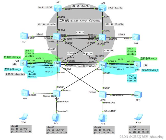
2、FW1,FW2部署虚拟防火墙,创建虚拟系统VPN_A、VPN_B分别对应业务VLAN10与VLAN20的业务
1)配置FW1,其中虚拟系统VPN_A包含vlan120,vlan121接口,虚拟系统VPN_B包含vlan122,vlan123接口
FW1:
vsys enable
vsys name VPN_A
 assign vlan 120
 assign vlan 121

vsys name VPN_B
 assign vlan 122
 assign vlan 123
#
#需要在根墙开启相应接口
int vlanif120
int vlanif121
int vlanif122
int vlanif123

#切换到虚拟系统VPN_A
switch vsys VPN_A
sys
interface Vlanif120
 ip binding -instance VPN_A
 ip address 172.16.120.12 255.255.255.0
#
interface Vlanif121
 ip binding -instance VPN_A
 ip address 172.16.121.12 255.255.255.0
#

#切换到虚拟系统VPN_B
switch vsys VPN_B
sys
interface Vlanif122
 ip binding -instance VPN_B
 ip address 172.16.122.12 255.255.255.0
#
interface Vlanif123
 ip binding -instance VPN_B
 ip address 172.16.123.12 255.255.255.0
#

#
注意: vlan121,vlan123连接外网,vlan120,vlan122连接内网
#配置虚拟系统VPN_A的安全区域
switch vsys VPN_A
sys
firewall zone trust
 set priority 85
 add interface Vlanif120
#
firewall zone untrust
 set priority 5
 add interface Virtual-if1
 add interface Vlanif121
#
#配置虚拟系统VPN_B的安全区域
switch vsys VPN_B
sys
firewall zone trust
 set priority 85
 add interface Vlanif122
#
firewall zone untrust
 set priority 5
 add interface Virtual-if2
 add interface Vlanif123
#
2)配置FW2,其中虚拟系统VPN_A包含vlan130,vlan131接口,虚拟系统VPN_B包含vlan132,vlan133接口
FW2:
vsys enable
vsys name VPN_A
 assign vlan 130
 assign vlan 131

vsys name VPN_B 2
 assign vlan 132
 assign vlan 133
#
#需要在根墙开启相应接口
int vlanif130
int vlanif131
int vlanif132
int vlanif133

#切换到虚拟系统VPN_A
switch vsys VPN_A
sys
interface Vlanif130
 ip binding -instance VPN_A
 ip address 172.16.130.13 255.255.255.0
#
interface Vlanif131
 ip binding -instance VPN_A
 ip address 172.16.131.13 255.255.255.0
#

#切换到虚拟系统VPN_B
switch vsys VPN_B
sys
interface Vlanif132
 ip binding -instance VPN_B
 ip address 172.16.132.13 255.255.255.0
#
interface Vlanif133
 ip binding -instance VPN_B
 ip address 172.16.133.13 255.255.255.0
#
#
注意:vlan131,vlan133连接外网,vlan130,vlan132连接内网
#配置虚拟系统VPN_A的安全区域
switch vsys VPN_A
sys
firewall zone trust
 set priority 85
 add interface Vlanif130
#
firewall zone untrust
 set priority 5
 add interface Virtual-if1
 add interface Vlanif131
#配置虚拟系统VPN_B的安全区域
switch vsys VPN_B
sys
firewall zone trust
 set priority 85
 add interface Vlanif132
#
firewall zone untrust
 set priority 5
 add interface Virtual-if2
 add interface Vlanif133
#
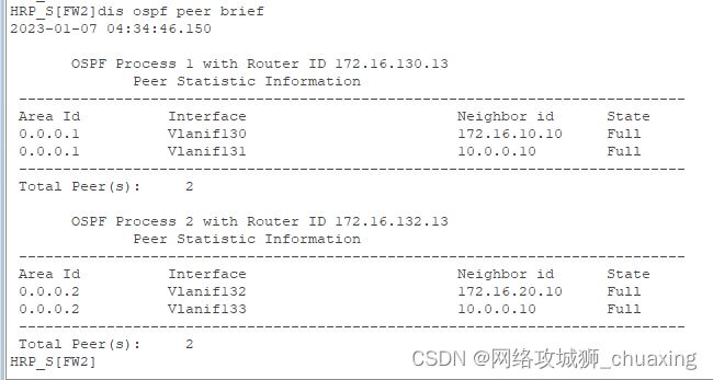
3、设置VPN_A、VPN_B分别与S3、S4建立OSPF邻居关系,分别划分到区域1与区域2
FW1:
FW1:
ospf 1 -instance VPN_A
#禁止路由环路检测,直接进行路由计算
 -instance-capability simple
 area 0.0.0.1
  network 172.16.0.0 0.0.255.255
#

ospf 2 -instance VPN_B
#禁止路由环路检测,直接进行路由计算
 -instance-capability simple
 area 0.0.0.2
  network 172.16.0.0 0.0.255.255
#
[S3-ospf-100]di th
#
ospf 100 router-id 10.0.0.9
 silent-interface Vlanif10
 silent-interface Vlanif20
 area 0.0.0.0
  authentication-mode md5 1 plain huawei
  network 172.16.79.9 0.0.0.0
  network 172.16.89.9 0.0.0.0
 #需要在区域1和区域2宣告外网口,vlanif121和vlanif123
 area 0.0.0.1
  network 172.16.121.9 0.0.0.0
 area 0.0.0.2
  network 172.16.123.9 0.0.0.0
 area 0.0.0.3
  network 172.16.254.9 0.0.0.0
  vlink-peer 10.0.0.10 authentication-null
#
FW2:
FW2:
ospf 1 -instance VPN_A
#禁止路由环路检测,直接进行路由计算
 -instance-capability simple
 area 0.0.0.1
  network 172.16.0.0 0.0.255.255
#

ospf 2 -instance VPN_B
#禁止路由环路检测,直接进行路由计算
 -instance-capability simple
 area 0.0.0.2
  network 172.16.0.0 0.0.255.255
#
[S4-ospf-100]di th
#
ospf 100 router-id 10.0.0.10
 area 0.0.0.0
  authentication-mode md5 1 plain huawei
  network 172.16.108.10 0.0.0.0
  network 172.16.107.10 0.0.0.0
#需要在区域1和区域2宣告外网口,vlanif131和vlanif133
 area 0.0.0.1
  network 172.16.131.10 0.0.0.0
 area 0.0.0.2
  network 172.16.133.10 0.0.0.0
 area 0.0.0.3
  network 172.16.254.10 0.0.0.0
  vlink-peer 10.0.0.9 authentication-null
#
4、配置静态路由实现虚拟系统之间互访,VLAN10访问VLAN20的业务流量通过虚拟系统之间完成互通,避免次优路径
FW1:
ip route-static -instance VPN_A 172.16.20.0 255.255.255.0 -instance VPN_B
ip route-static -instance VPN_B 172.16.10.0 255.255.255.0 -instance VPN_A
#在VPN实例的OSPF进程中引入静态路由
HRP_M[FW1-ospf-1]import-route static
#
HRP_M[FW1-ospf-2]import-route static
FW2:
ip route-static -instance VPN_A 172.16.20.0 255.255.255.0 -instance VPN_B
ip route-static -instance VPN_B 172.16.10.0 255.255.255.0 -instance VPN_A
#
5、安全策略
FW1、FW2:
switch vsys VPN_A
sys
security-policy
 rule name local_any
  source-zone local
  action permit
 rule name trust_untrust
  source-zone trust
  destination-zone untrust
  action permit
 rule name untrust_trust
  source-zone untrust
  destination-zone trust
  destination-address 172.16.10.0 mask 255.255.255.0
  action permit
#
switch vsys VPN_B
sys
security-policy
 rule name local_any
  source-zone local
  action permit
 rule name trust_untrust
  source-zone trust
  destination-zone untrust
  action permit
 rule name untrust_trust
  source-zone untrust
  destination-zone trust
  destination-address 172.16.20.0 mask 255.255.255.0
  action permit
#
#使能防火墙接口的ICMP TTL超时报文的发送功能
icmp ttl-exceeded send
6、验证
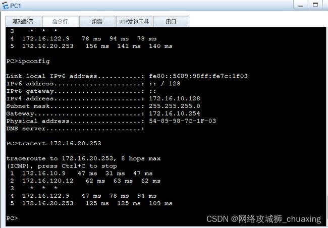
PC1获取到的地址:

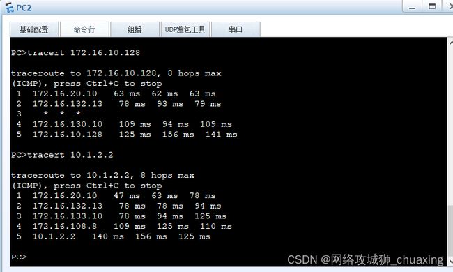
PC2获取到的地址:

PC1与PC2互访是通过虚拟系统之间完成的:

PC2 访问R2的loopback 0接口:


