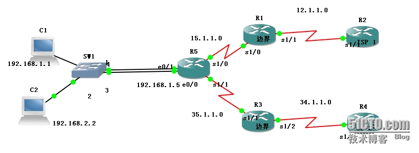
关于OSPF 默认路由的分布以及链路冗余并启用NAT
 首先 R1上配置
int s1/1
ip add 12.1.1.1 255.255.255.0
ip nat outside
no shu
int s1/0
ip add 15.1.1.1 255.255.255.0
ip nat inside
no shu
ip route 0.0.0.0 0.0.0.0 12.1.1.2
router ospf 100
net 15.1.1.0 0.0.0.255
net 12.1.1.0 0.0.0.255
default-information originate
acce-list 100 permit ip any any
ip nat pool ccnp 12.1.1.1 12.1.1.1 255.255.255.0
ip nat inside source list 100 pool ccnp overload
R2上配置
int s1/1
ip add 12.1.1.2 255.255.255.0
no shu
int lo0
ip add 2.2.2.2
no shu
R3上配置
int s1/1
ip add 35.1.1.3 255.255.255.0
ip nat inside
no shu
int s1/2
ip add 34.1.1.3 255.255.255.0
ip nat outside
no shu
ip route 0.0.0.0 0.0.0.0 34.1.1.4
router ospf 100
net 35.1.1.0 0.0.0.255
default-information originate always metric 10 把R3上默认路由的metric设为10
acce-list 100 permit ip any any
ip nat pool ccnp 34.1.1.3 34.1.1.4 255.255.255.0
ip nat inside source list 100 pool ccnp overload
在R4上配置
int s1/2
ip add 34.1.1.4 255.255.255.0
no shu
int lo0
ip add 4.4.4.4 255.255.255.0
no shu
在R5上配置
int s1/0
ip add 15.1.1.5 255.255.255.0
no shu
int s1/1
ip add 35.1.1.5 255.255.255.0
no shu
int e0/0
ip add 192.168.1.5 255.255.255.0
no shu
int e0/1
ip add 192.168.2.5 255.255.255.0 这里也可以通过配置子接口来实现
no shu
router ospf 100
net 35.1.1.0 0.0.0.255
net 15.1.1.0 0.0.0.255
net 192.168.1.0 0.0.0.255
net 192.168.2.0 0.0.0.255
然后配置PC1 192.168.1.1 PC2 192.168.2.2
所有配置完成后,我们就可以来测试:这个拓扑中有2条路径连接到ISP,这在现实环境中可以保证链路的冗余,当其中一条路径出现问题后另外一条可以继续使用,保证网络的稳定。
这里如果2条路径没有问题时,如果PC1想上Internat就会选择R1的路径,因为R1默认路由的metric比R3的小,测试如下:
 能够到达ISP1
 显示到ISP2主机部可达;
当我们把R1的S1/1的端口shutdown后,可以发现:
 此时PC1可以到达ISP2,那么这时PC1肯定不能到达ISP1的,因为R1的S1/1端口已经shutdown了。
这个实验中用到的知识点有OSPF路由的配置、ospf默认路由的分布以及metric值得修改以及PAT的配置。
本文出自 “rookie cisco” 博客,谢绝转载!