OpenRisc-54-play with OpenRISC based atlys board
1.OpenRISC 1200 soft processor
Introduction
The OpenRISC 1200 (OR1200) is a synthesizable CPU core maintained by developers at OpenCores.org . The OR1200 design is an open source implementation of the OpenRISC 1000 RISC architecture. The Verilog RTL description is released under the GNU Lesser General Public License ( LGPL ). For more information see OpenRisc 1200 Specification document or go to the OpenRISC 1200 IP Core Specification page.
Since the 1st of November 2007 OpenCores is maintained by ORSoC . For a long period of time ORSoC has worked closely to OpenCores, both with the community and with development of the technology.
Reading instructions
This is the first part of the OpenRISC tutorial. The chapters should be read in date order, starting with the oldest. At the end of every chapter there are four links called TOP, NEXT, PREVIOUS and TOC. The TOP link takes you the top of the current chapter. The NEXT link takes you to the next chapter, the PREVIOUS link takes you to the previous chapter and the TOC link takes you to the table of contents page. You can also click the Modesty-CoreX label and then click Index to get to TOC page.

A review of the OpenRISC architecture and implementation
Julius Baxter has written a great review of open source development and especially the OpenRISC project in his master's thesis. It starts like this:
This document is a look at both the technical aspects of a microprocessor project and open source development. The technology involved in microprocessors and the philosophy and practices of open source development are first explained, before the OpenRISC project, a project combining the two, is presented. This project is then evaluated and the results of the development effort and the role open source has played are discussed. Read ithere.
OpenRISC community portal
This wiki is the main entrance to information about the OpenRISC project. It has a lot of useful information about the development process. It took me a long time to find this page. Please add a link on the opencores.org site.
Architecture
The IP core of the OR1200 is implemented in the Verilog HDL . As an open source core, the design is fully public and may be downloaded and modified by any individual. The official implementation is maintained by developers at OpenCores.org. The implementation specifies a power management unit, debug unit, tick timer, programmable interrupt controller (PIC), central processing unit (CPU), and memory management hardware. Peripheral systems and a memory subsystem may be added using the processor's implementation of a standardized 32-bit Wishbone bus interface.
CPU/DSP
The OR1200 CPU is an implementation of the 32-bit ORBIS32 instruction set architecture (ISA) and (optionally) ORFP32X ISA implementing IEEE-754 compliant single precision floating point support. The ISA has five instruction formats and supports two addressing modes: register indirect with displacement, and PC-relative. The implementation has a single-issue 5-stage pipeline and is capable of single cycle execution on most instructions. The CPU also contains a MAC unit in order to better support digital signal processing ( DSP ) applications.

General Microarchitecture
- Central CPU/DSP block
- IEEE 754 compliant single precision FPU
- Direct mapped data cache
- Direct mapped instruction cache
- Data MMU based on hash-based DTLB
- Instruction MMU based on hash-based ITLB
- Power management unit and power management interface
- Tick timer
- Debug unit and development interface
- Interrupt controller and interrupt interface
- Instruction and Data WISHBONE B3 compliant interfaces
ORPSoC - OpenRISC Reference Platform SoC
ORPSoC is the OpenRISC Reference Platform System-on-Chip. This project implements a platform for OpenRISC development. It provides a reference SoC, primarily for the testing and development of OpenRISC processors, and a set of pre-built SoCs for various FPGA boards.
Downloading ORPSoC
The RTL source, test software and scripts can be downloaded from the OpenRISC project subversion (svn) repository. The sources can be checked out with the following command:
svn co http://opencores.org/ocsvn/openrisc/openrisc/trunk/orpsocv2
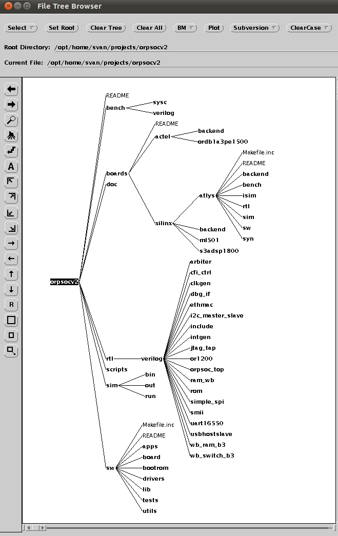
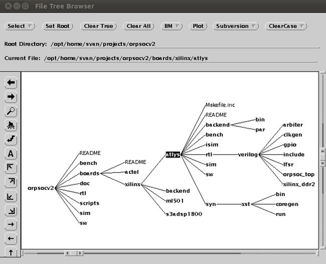
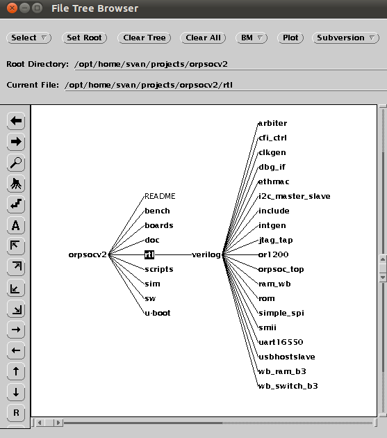
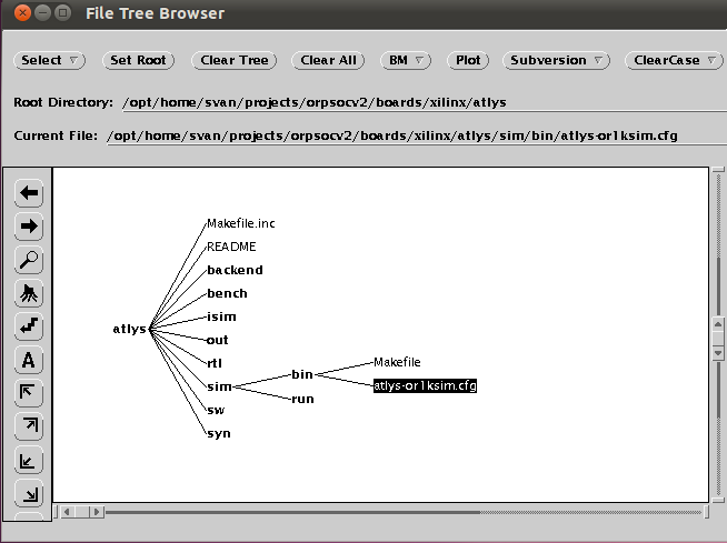
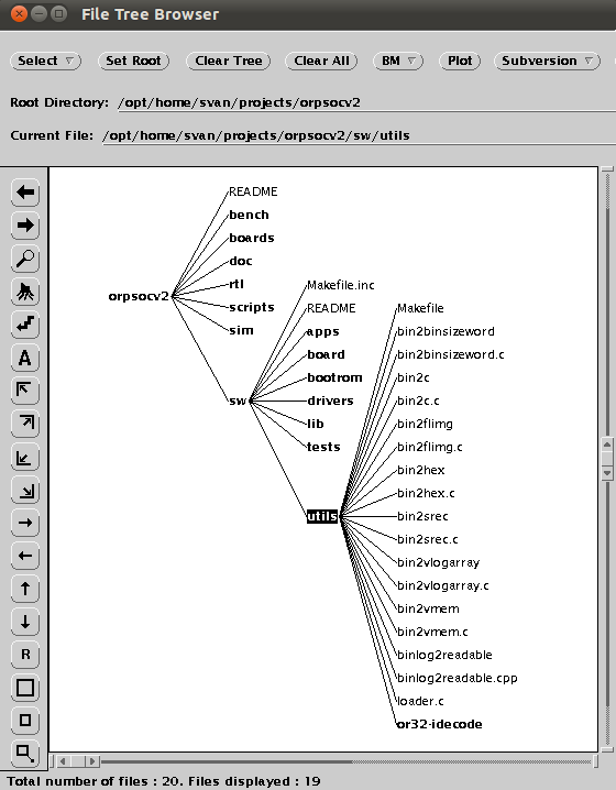
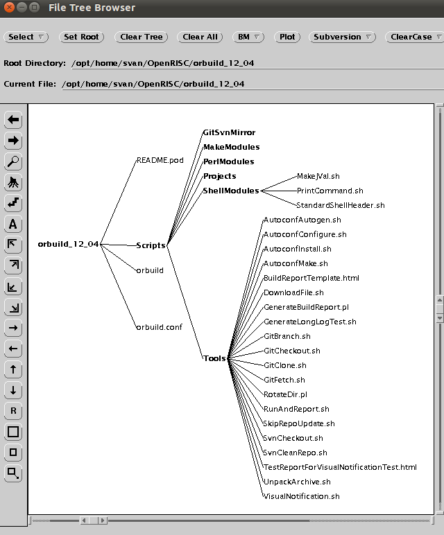
After unpacking the ORPSoC installation looks like this.
GNU toolchain
The GNU Toolchainis a blanket term for a collection of programming tools produced by the GNU Project.These tools form a toolchain (suite of tools used in a serial manner) used for developing applications and operating systems. The GNU toolchain plays a vital role in development of Linux kernel, BSD, and software for embedded systems.
Before we can start using ORPSoC platform we have to download and install the OpenRISC GNU newlib toolchain. The link on the GNU tooolchain web page doesn't work for some reason, but the GNU toolchain can be downloaded from this OpenCores FTP site: ftp://ocuser:[email protected]/toolchain/or32-elf-1.0rc1-x86.tar.bz2
Here is a link to download the latest version of the toolchain. Observe, not exactly the same installation as described here below.
Newlib library
The OpenRISC 1000 port of the newlib library aims to provide a library to provide support for running on bare-metal hardware without an operating system. It is also used when running the GNU toolchain regression suite. The library is linked when using the newlib version of the GCC compiler (or32-elf-gcc) and adding the -mnewlib option. The target board is specified by -mboardname. If not board is specified, the default (-mor1ksim) is suitable for use with Or1ksim simulator.
GNU toolchain installation
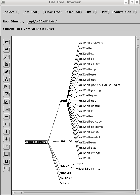
The programs must be installed in the /opt directory. Use the following commands to unzip and unpack the downloaded file:
cd /opt
sudo tar xjf ...../or32-elf-1.0rc1-x86.tar.bz2
Add the following symbolic links which helps when switching to new updated version later on :
sudo ln -s or32-elf-1.0rc1 or32-elf
sudo ln -s or1ksim-0.5.1rc1 or1ksim
Add the following path to the PATH varable in your .profile file:
PATH=/opt/or32-elf/bin:/opt/or1ksim/bin:$PATH
Installing in a Linux 64 bits system
When installing the GNU toolchain (32 bits Linux) in Debian Squeeze (64bits) the following i386 (32bits) libraries were missing:
- libmpfr.so.1
- libmpc.so.2
- libgmp.so.3
Finding and installing these i386 libraries in an amd64 system is not that simple. Can anyone explain for me how to do it. One problem is that there are 64 bits versions of some of these libraries installed already.
Building the toolchain yourself
There is now a script environment called orbuild that can be downloaded and used to build the toolchain from source. For more information see Using orbuild.
Choosing a development board
From the installation we can see that there are support for a number of development boards. We look for a board with a SPARTAN-6 FPGA and find the Digilent Atlys board. Let's give it a try. I will order the board at once.
The MinSoC project
The Minimal OpenRISC System on Chip (minsoc) is a system on chip (SoC) implementation with standard IP cores available at OpenCores. This implementation consists of a standard project comprehending the standard IP cores necessary for a SoC embedding the OpenRISC implementation OR1200.
This project idea is to offer a synthesizable SoC which can be uploaded to every FPGA and be compatible with every FPGA board without the requirement of changing its code. In order to deliver such a project, the project has been based on a standard memory implementation and the Advanced Debug System, which allows system debug and software upload with the same cables used for FPGA configuration.
Getting help
If we need help with the development we can post to the OpenRISC forum or send an email [email protected]. There are also four mailing list you can subscribe to. It seems most of the discussion about OpenRISC takes place in these mailing lists. A pattern of usage seems to be emerging, where general users ask their questions on the OpenRISC forum, while developers discuss new design ideas and post patches on the four mailing lists. Click the first link to subscribe to the list and click the second link to send an email to the list.
- OpenRISC mailing list on openrisc.net
- Linux mailing list on openrisc.net
- OpenRISC mailing list on opencores.org
- Wishbone mailing list on opencores.org
IRC
Most of the regular contributors can be found on channel #opencores at freenode.net. They are a friendly bunch, and a good source of advice.
Links
Here are links to companies using the OpenRISC processor and to other interesting information about the OpenRISC processor.
AntMicro
ÅAC Microtec Wiki
EMBECOSM
ORSoC
Beginners' Guide to OpenRISC
2.Digilent Atlys SPARTAN-6 development board
Introduction
It didn't take more than one day for the board to arrive. Here it is

and it looks like this:

The size of the board is 13.5 x 12 cm and it contains the following:
- Xilinx Spartan-6 LX45 FPGA, 324-pin BGA package
- 128Mbyte DDR2 16-bit wide data
- 10/100/1000 Ethernet PHY
- On-board USB2 ports for programming & data transfer
- USB-UART and USB-HID port (for mouse/keyboard)
- Two HDMI video input ports & two HDMI output ports
- AC-97 Codec with line-in, line-out, mic, & headphone
- Real time power monitors on all power rails
- 16Mbyte x4 SPI Flash for configuration & data storage
- 100MHz CMOS oscillator
- 48 I/O’s routed to expansion connectors
- GPIO includes 8 LEDs, 6 buttons, & 8 slide switches
- Ships with a 20W power supply and USB cable

For more information see Diligent webpage .
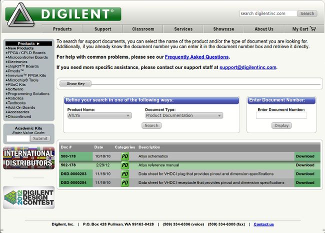
Documentation
The board comes without any documentation. All documents about the Atlys board can be downloaded from the Digilent support page .
Built-in self test
A demonstration configuration is loaded into the SPI Flash ROM on the Atlys board during manufacturing. This demo, also available on the Digilent website, can serve as a board verification test since it interacts with all devices and ports on the board. When the Atlys board powers up, if the demonstration image is present in the SPI Flash, the DDR is tested, and then a bitmap image file will be transferred from the SPI Flash into DDR2. This image will be driven out the HDMI J2 port for display on a DVI/HDMI-compatible monitor. The slide switches are connected to the user LEDs. The user buttons BTNU, BTND, BTNR, BTNL, BTNC, and RESET cause varying sine-wave frequencies to be driven on the LINE OUT and HP OUT audio ports. Here is the test setup.

Configuring the board
After power-on, the FPGA on the Atlys board must be configured (or programmed) before it can perform any functions. The FPGA can be configured in three ways: a USB-connected PC can configure the board using the JTAG port any time power is on, a configuration file stored in the SPI Flash ROM can be automatically transferred to the FPGA at power-on, or a programming file can be transferred from a USB memory stick attached to the USB HID port.
Design environment
We will use the Xilinx ISE Design Suite as our design environment for synthesizing designs and configuring the FPGA. For more information on how to download and install the Design Suite see this page.
Connecting the Atlys board to the computer
It seems that one big hurdle when starting a new FPGA project is to setup the connection between the development board and the computer. I will take you through this process and hopefully we will get the board connected and be able to configure the FPGA. In this example I have Ubuntu 12.04 installed in VirtualBox running on my MacBook Pro, but the same setup will work for other Linux flavors and computers.
There are two ways to connect the computer to the Atlys board:
1. Using the Xilinx Platform Cable USB

2. Using a standard USB cable and the Digilent Adept system.

The Digilent Adept system
The Adept port is compatible with Xilinx's iMPACT programming software if the Digilent Plug-In for Xilinx Tools is installed on the host PC. The plug-in automatically translates iMPACT-generated JTAG commands into formats compatible with the Digilent USB port, providing a seamless programming experience without leaving the Xilinx tool environment. Once the plug-in is installed, the "third party" programming option can be selected from the iMPACT tools menu, and iMPACT will work as if a Xilinx programming cable were being used. All Xilinx tools (iMPACT, ChipScope, EDK, etc.) can work with the plug-in, and they can be used in conjunction with Adept tools (like the power supply monitor). We will use this method of connecting to the board because we don't need any extra hardware. Let's start by installing some software.
Installing the Digilent cable drivers
First we add these two sofware packages:
- sudo apt-get install libusb-dev
- sudo apt-get install fxload
Next we have to install the Digilent plugins. Xilinx provide these plugins in their installation directory but they are not activated. Here is what we have to do in Design Suite 14.2:
Goto to directory /opt/Xilinx/14.2/ISE_DS/common/bin/lin/digilent
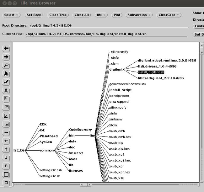
Execute the following command:
sudo ./install_digilent.sh /opt/Xilinx/14.2/ISE_DS/ISE

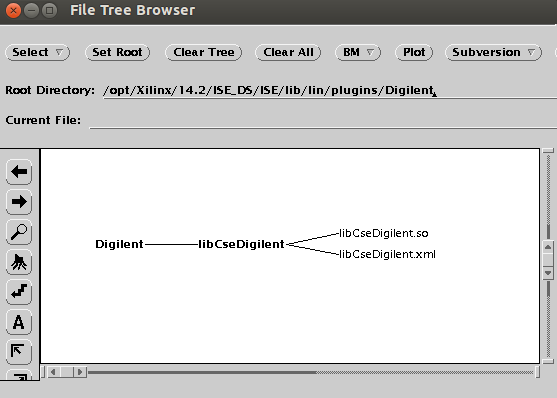
The Digilent plugins are installed here.
 l
l
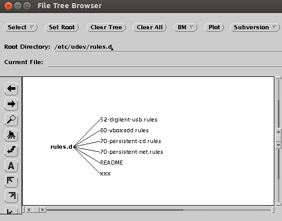
The USB rules file 52-digilent-usb.rules is installed here:
The rules file
The problem with this rules file is that in can only be run when we are logged in as root. To fix this problem we have to edit the file and change all SYSFS to ATTR (three locations).
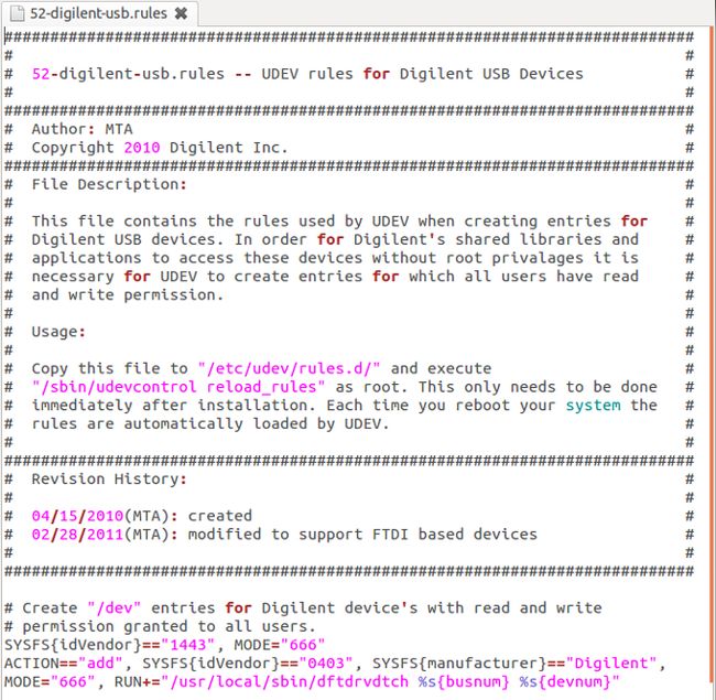
After editing the file we have to reboot the system and we are ready to ride. If we are using VirtualBox we have to make sure the USB device is enabled in the Device menu. For older versions of Linux we have to change the first MODE=666" to MODE="666", GROUP="plugdev"
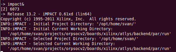
Using iMPACT
Let's find out if we can identify the board using iMPACT. First we connect the USB cable from a USB port on our computer to the mini-USB prog port on the Atlys board. We power up the board and start iMPACT. Here is the iMPACT main window telling us that the board has been identified.
 l
l
3.Using ORPSoC
Introduction
ORPSoC is intended to be a reference implementation of processors in the OpenRISC family. It provides a smallest-possible reference system, primarily for testing of the processors. It also provides systems intended to be synthesized and programmed on physical hardware. The reference system is the least complex implementation and consists of just enough to test the processor’s functionality. The board-targeted builds typically include many additional peripherals. For more information read the ORPSoC User Guide found in the doc directory of the ORPSoC installation.
Project organization
The ORPSoC project is intended to serve dual purposes. One is to act as a development platform for OpenRISC processors, and as a development platform of OpenRISC-based SoCs targeted at specific hardware. Organising a single project to satisfy these requirements can lead to some overlap and redundancy. The reference implementation based in the root (base directory) of the project contains enough components to create a simple OpenRISC-based SoC. Each board build is intended to implement as fully-featured a system as possible, depending on the targeted hardware. The project is organised in such a way that each board build can use both the reference implementation’s RTL modules and software, as well as its own set of RTL and software. The reference implementation is limited to what is available in the RTL and software directories in the root of the project, and is not technology dependent.
The Atlys board
We will start by finding the Atlys board setup.
Before we start
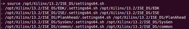
Before we start the design phase we have to make sure the Xilinx Design Suite is installed and that the environment variable XILINX is set.
Design
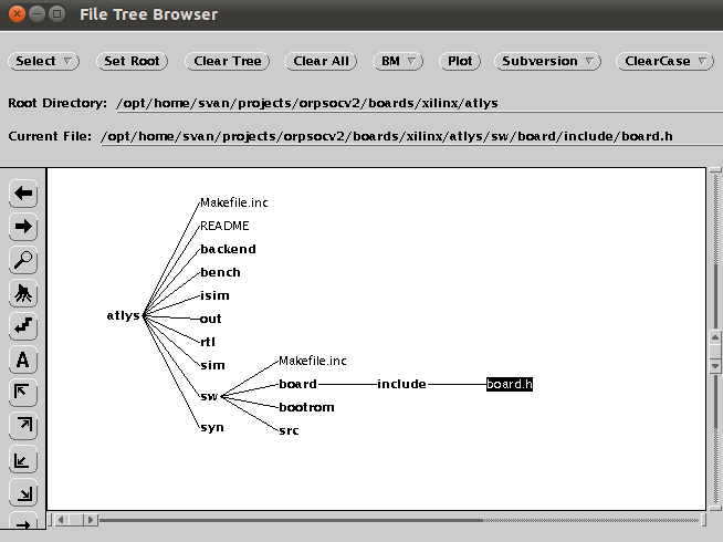
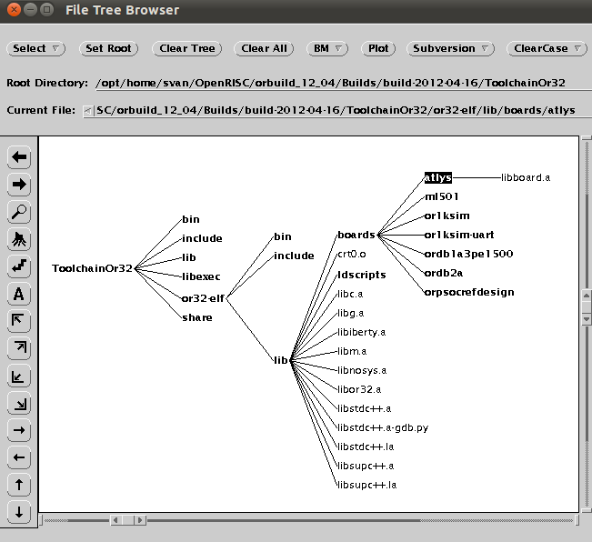
The design is made up of a number of Verilog HDL files. They reside in two different directory. One directory that holds all the code that is common to all board designs found here:
And one board specific design directory as shown in the screenplot of the atlys board directory structure. The syntesis script will pick up all the Verilog design files to build the complete system.
Synthesis
Synthesis of the board port for the Xilinx technology with the XST synthesis tool can be run in the board’s <syn/xst/run> path with the following command: <make all>
This will create an NGC file in <syn/xst/run> named <orpsoc.ngc>. Hopefully it’s all automated enough so that, as long as the design is simulating as desired, the correct set of RTL will be picked up and synthesized without any need for customising scripts for the tool.

User constraints file
A Xilinx User Constraints File (UCF) is in the board’s <backend/par/bin> path. It is named <atlys.ucf>. It should be edited if any extra I/O or constraints are required.
Mappping and place & route
Mapping and place & route of the design can be run from the board’s <backend/par/run> path with the following command: <make orpsoc.ncd>. The makefile used can be found in the <......./boards/xilinx/atlys/backend/par/bin> directory. Here is an excerpt from the makefile showing the backend design flow:

Place & route results
The results from the place & route tool can be found in the logfile <orpsoc.par>:

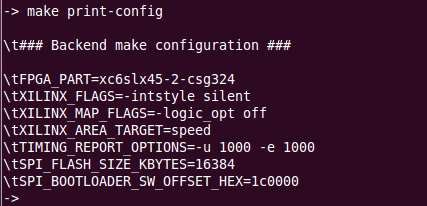
Options
To get a list of options that can be set when running the backend flow, run the following command:
make print-config
Generate timing report
The trace tool can be used to generate a timing report of the post-place and route design:
make timingreport
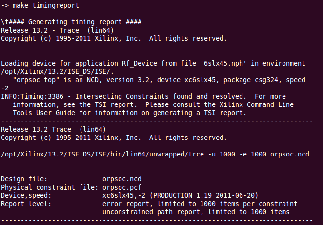
Here is the result:
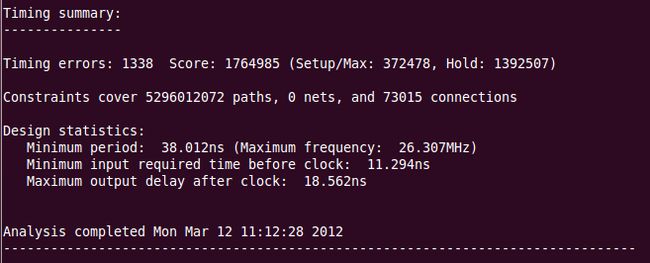
We have 1338 timing errors. Before we continue we have to investigate these errors. The timing report result file is called <orpsoc.twr>. Analyzing the this we find the following timing errors.


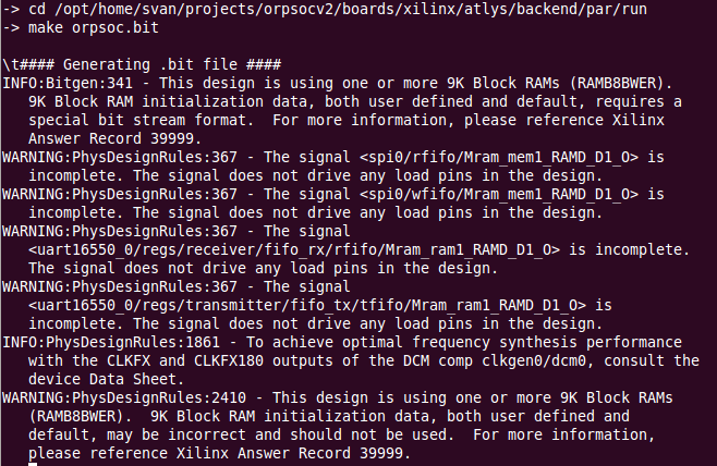
Generating the bitstream file
The bitstream file is used to configure the FPGA device. The configuration file generation is run from the .../atlys/backend/par/run directory using the command: make orpsoc.bit
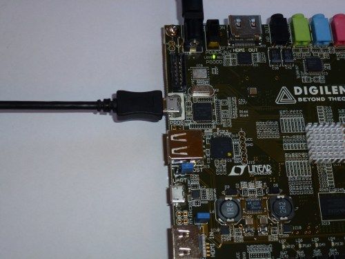
Downloading the bitstream
We are going to use the Xilinx configuration tool called iMPACT to configure the SPARTAN-6 FPGA on the Atlys board. The first thing we have to do is connecting our board to the computer we use for our development work using a USB cable.
Then start iMPACT.
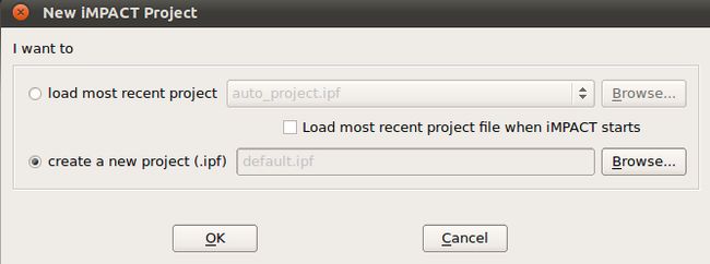
We will create a new iMPACT project.
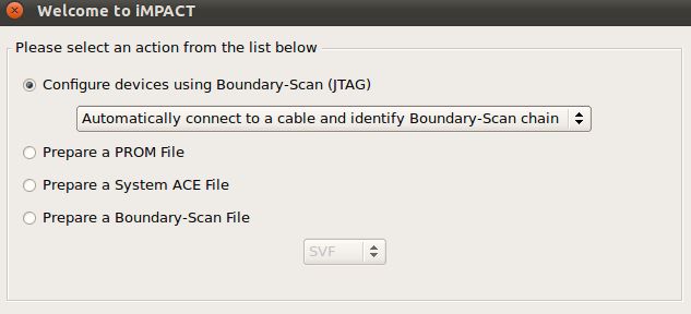
The iMPACT tool will connect to the boundary scan chain on the board and identify the FPGA.
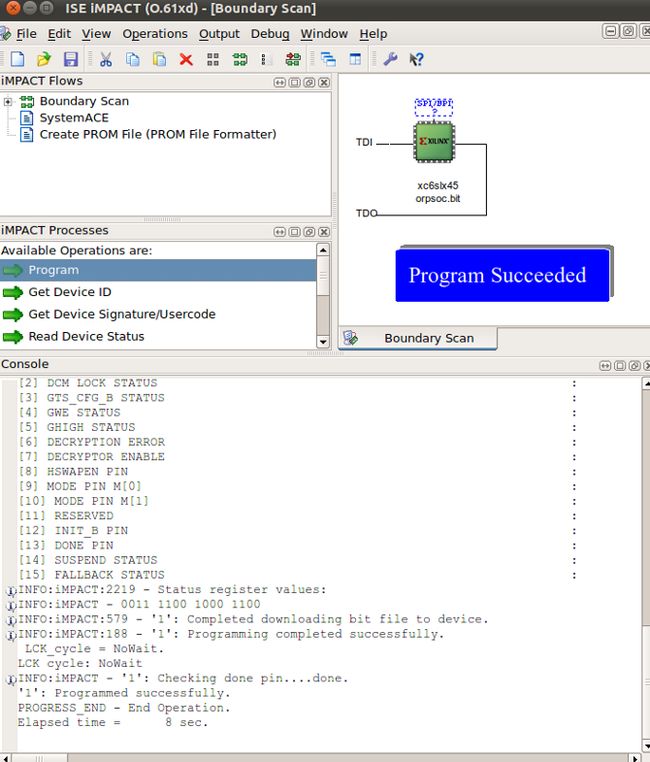
To add a configuration file we right-click the FPGA icon and select <Assign New Configuration File> and find the configuration file <orpsoc.bit>.

When double-clicking the Program operation entry the configuration will start. After a few seconds the configuration has finished.
4.Simulating ORPSoC using ISim
Introduction
In Design Suite 13.2 the default HDL simulator is ISim. The ORPSoC package is setup to run ModelSim. To be able to use ISim we will modify the ModelSim scripts to run ISim instead. For more information about ISim, read the ISim HDL simulator blog entry. For more information about running simulations, see this page .
Simulation environment
We will add a subdirectory called isim in the atlys directory and define the following simulation environment.

Using environment variables
To simplify the setup we define two environment variables and add these two lines in our .bashrc file:
export ORPSOC_HOME=/opt/home/svan/projects/orpsocv2
export ATLYS_HOME=/opt/home/svan/projects/orpsocv2/boards/xilinx/atlys
Setting up the simulation project file
The simulation project file < orpsoc_sim.prj > contains all verilog files that are included in the simulation setup and that will be compiled and elaborated when running ISim. Here are the first lines of this file:

Setting up the command file
The command file contains all the command line options sent to the fuse program when running the compilation and elaboration. For some reason we can't use environment variables in the command file.
-i <dir> points to a directory holding include files needed during simulation
-L <Lib> includes a precompiled verilog library from Xilinx

Set test conditions
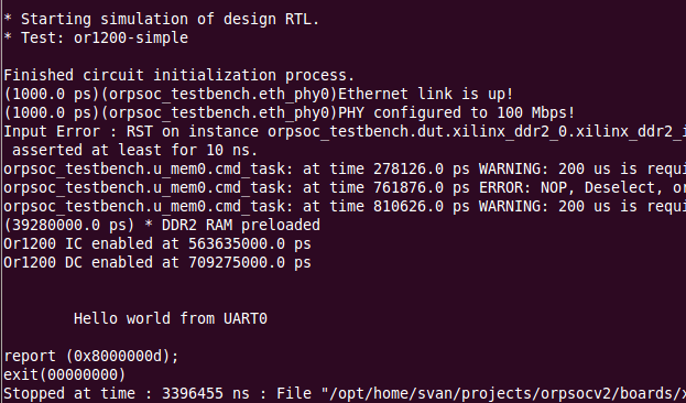
The file <test-defines.v> is used for setting up test conditions and selecting a testcase. The variable TEST_NAME_STRING defines which test to run. We select <or1200-simple> and copy the modified <test-defines.v> file to the directory <$ATLYS_HOME/isim/include> before starting the compilation. I cant find this file in the current version of ORPScC but you can make your own adding the defines shown here below.
Preloading DDR2 memory
The program that will be executed during the simulation will reside in the DDR2 memory. To enable the preloading of the DDR memory we add the following line in the <test-defines.v> file:
`define PRELOAD_RAM

The name of the loaded image is <sram.vmem> and it must reside in the directory $ATLYS_HOME/isim. For now we will copy the file from $ORPSOC_HOME/sim/run. Later on we will write our own c-programs and generate the <sram.vmem> file.
Bootrom module
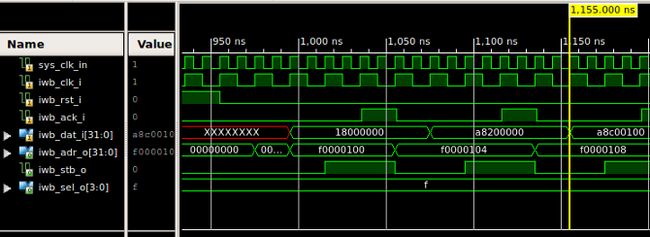
The system starts by executing some code out of the bootrom module. This module is typically on the processor's instruction bus at address 0xf0000100 and will contain some instructions - enough to do some basic bootstrapping. The file <rom.v> contains the bootrom code. It is possible to add our own bootstrapping code but we will modify the <rom.v> file and enable the built-in boot code.

Compilation and elaboration
Use the following command to run the compilation and elaboration. We must remember to include the Xilinx glbl file (work.glbl):
fuse work.orpsoc_testbench work.glbl -f command/isim_commands.def -o test.exe
Running a simulation
The executable file is named test.exe. We use the following command to run a simulation:
./test.exe -tclbatch tcl/run_test.tcl
The run_test.tcl file looks like this:

 l
l
We have a working simulation setup. This is what the final setup looks like:
 l
l
Displaying waveforms
During the simulation all the signal activity has been stored in the file <isim.wdb>. We can use the ISim GUI to look at all the signal waveforms using this command:
isimgui -view isim.wdb

Analyzing the design
Using the waveform viewer we can analyze our design and look for errors. We will start by investigating the clock generation and the reset sequence. Let's take a closer look at the clkgen0 block.


Now let's take a look at the cpu (or1200_top0) and see what happens after reset.

From the waveform plot we can see that the processor boots from address 0xf0000100 and starts executing the bootstrap code in the bootrom.
 l
l
Calibrating the DDR2 memory interface
From this plot we can see that the DDR2 memory takes almost 40us before it responds. We notice that the calib_done signal coming from the DDR2 interface goes high after 39us. That is the time it takes for the DDR2 memory controller to calibrate itself.

Is there a way to skip this calibaration time in the simulation?
Using makefiles
I am not an expert in writing makefiles. This whole flow can run from a makefile but that is something that can wait.
5.Writing an application program
Introduction
A processor without a program to execute is like a car without gas. It is useless. We will write our first c-program, compile it, run it in the OR1K simulator and in the real system. We will use the OpenRISC GNU toolchain which we have already installed .
The OpenRISC GNU toolchain
The newlib-based toolchain contains the standard GCC libraries of libgcc and libstdc++-v3 and those included in newlib; libc, libm and libgloss . The OpenRISC port provides a set of support functions for controling basic CPU functions. The libgloss port provides basic board support that should allow easy addition of new boards.
Bare metal support
The idea behind a compiler providing bare metal support is that it allows users in the process of developing OpenRISC systems to quickly compile simple programs and have them run on the board. By providing access to a basic C library and UART I/O, which can help test the basics of the system through hello-world type applications and other custom diagnostics C programs the developer can quickly determine if it is functioning as expected. It is anticipated all boards builds included in ORPSoC will have their boards also supported in libgloss, which provides a quick and easy way for users of the board ports to compile and run code on the system to check things are operational.
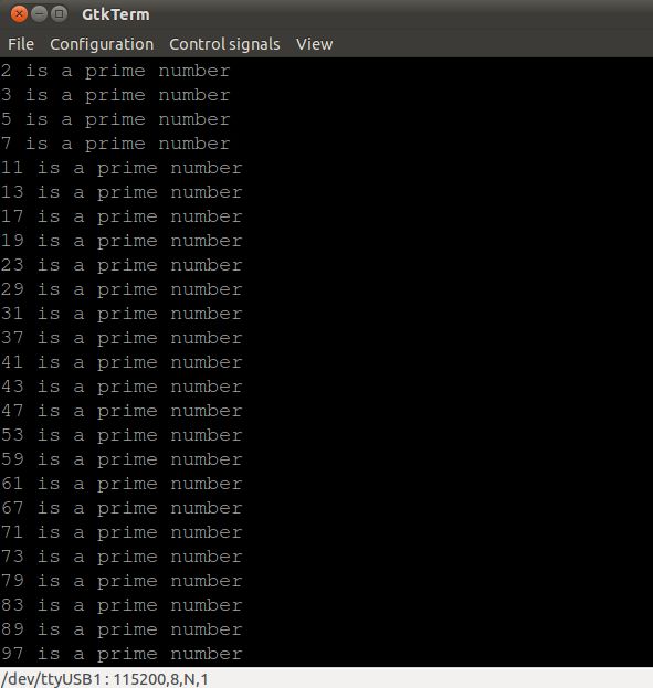
The c-program
Here is the program we are going to use. It calculates all prime numbers in the range we specify.

Create a board file
There is no board file for the Atlys board so we have create one. We can download a template file from here and rename it to atlys.S and make the changes needed. The only thing we will change is the board frequency to 50000000.
/*
* Define symbols to be used during startup - file is linked at compile time
*
*/
.global _board_mem_base
.global _board_mem_size
.global _board_clk_freq
_board_mem_base: .long 0x0
_board_mem_size: .long 0x800000
_board_clk_freq: .long 66666666
/* Peripheral information - Set base to 0 if not present*/
.global _board_uart_base
.global _board_uart_baud
.global _board_uart_IRQ
_board_uart_base: .long 0x90000000
_board_uart_baud: .long 115200
_board_uart_IRQ: .long 2
Compile the board file using this command: or32-elf-gcc -c atlys.S
Archive the compiled file using this commamnd: or32-elf-ar -rs libboard.a atlys.o
Copy the libboard.a to the directory "path_to_toolchain"/or32-elf/lib/boards/atlys
Compiling the program
At present the newlib libraries are not linked by default. The following command is used to compile our program:
or32-elf-gcc -mnewlib -mboard=atlys PrimeNumbers.c -o PrimeNumbers
The default linker script will place the code in RAM starting from address 0x0.
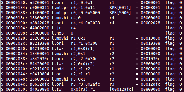
Generate an assembly listing
To study the generated code we can create an assembly listing using the following command:
or32-elf-objdump -d PrimeNumbers

Using the Or1ksim simulator
Or1ksim is a generic OpenRISC 1000 architecture simulator capable of emulating OpenRISC based computer systems. Or1ksim provides a range of features:
- Free, open source code, which can be used as a standalone simulator, or as a library.
- High level, fast, architecture simulation that allows early code analysis and system performance evaluation.
- Models of all major OpenCores peripheral and system controller cores and easy addition of new peripheral models.
- Easy configuration for different environments (memory configurations and sizes, OR1K processor model, configuration of peripheral devices).
- Remote debugging via TCP/IP with the GNU Debugger (GDB) using either the GDB Remote Serial Protocol or through a modeled JTAG interface.
- A library interface allowing simple OSCI TLM 2.0 SystemC integration.
Board configuration file
Or1ksim is configured through a board configuration file. This is specified through the -f parameter to the Or1ksim command, or passed as a string when initializing the Or1ksim library. Every board has a configuration file describing the hardware setup and other parameters. The Atlys board configuration file can be found here:
Running a simulation
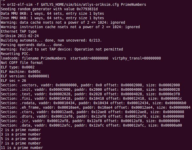
Here is the command to run the PrimeNumber program in the or1ksim simulator:
or32-elf-sim -f $ATLYS_HOME/sim/bin/atlys-or1ksim.cfg PrimeNumbers

Getting help
Use this command to display all options that can be used in the simulator: or32-elf-sim -h
Program tracing
Adding the -t option will display all instructions executed during the program run.
Running in the RTL simulator
We can also simulate our program in the RTL simulation environment we used in the last post. The compiled program must be converted to a format that can be loaded into the memory model. Here is how it can be done:
- Convert the compiled code to binary format
- Convert the binary format to vmem format.
- Load the vmem file during simulation
Here are the commands used:
or32-elf-objcopy -O binary PrimeNumbers PrimeNumbers.bin
/opt/home/svan/projects/orpsocv2/sw/utils/bin2vmem PrimeNumbers.bin > PrimeNumbers.vmem
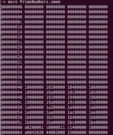
The PrimeNumbers.vmem file is copied to the isim directory and renamed to sram.vmem and we are ready to start the RTL simulation.
Writing a program to access GPIO
Byron asked the following question in the OpenCores forum: Do you know how to access the GPIO pins from C or C++?
Let's find out. The GPIO block is attached to the wishbone bus and has its own address range. We find the address in the board.h file:
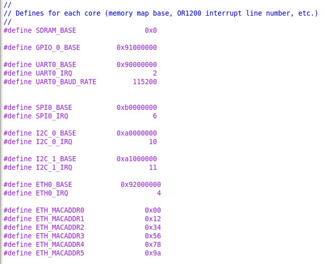
The GPIO base address is 0x91000000. To find out the GPIO register setup we look in the rtl directory and find gpio.v

Now we have all the information we need and can write our c-program:

We compile the program and generate the sram.vmem file to be included in the simulation. Here is the result from the RTL simulation.
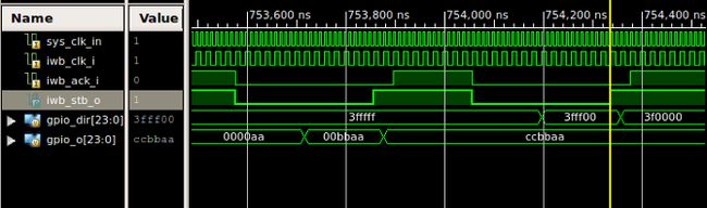
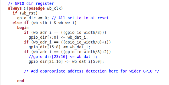
Did you notice
You may wonder why the direction registrer holds 0x3fffff instead of 0xffffff. Here is the explanation taken from the gpio.v file:
Running on real hardware
We are ready to download the program and run it on our system. There is just one catch, we don't have a simple method to do it. We would normally use the gdb debugger, connect to our target and download the program to the SDRAM and then run it using gdb commands. The OpenRISC gdb debugger <or32-elf-gdb> will not work with the Xilinx USB cable and there is no other debug solution available. We have to find another way to load and run the program.
Loading the program from SPI flash memory
Using the Xilinx IMPACT tool we can load the program to the SPI flash. We only need a method to copy the flash content to the SDRAM and start executing the program. We have to install a bootloader program in boot rom.
Here is how we will do it:
- Generate the bootloader program
- Add the bootloader in boot rom
- Synthesis the RTL code
- Map and place & route
- Generate bitstream
- Configure the FPGA using iMPACT
- Write the application program
- Compile the program
- Generate the flash prom image
- Load the SPI flash using iMPACT
- Hit the reset button on the board
- Hopefully the program will run successfully
Let's find out if this will work.
Running a RTL simulation
We will start by running a RTL simulation to figure out what exatly is going on. We will use the same setup but change the bootrom code and disable the preloading of RAM.

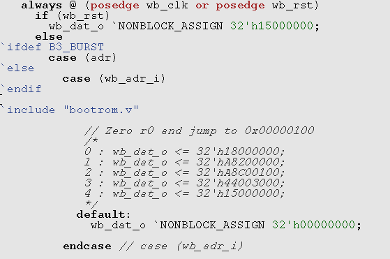
Fixing the bootrom code
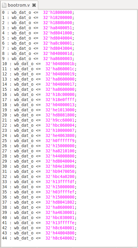
The boot loader program can be found in the file: $ORSPSOC_HOME/sv/bootrom/bootrom.S . Here is the beginning of the code.

The compiled and converted code looks like this:
Adding the flash image code
Before we can simulate the setup we have to prepare the flash image of our application program. This data file will be loaded to the flash memory model during simulation and then copied to the system RAM. The flash image used is stored in a file called flash.in which must be stored in the simulation work directory (isim). We will use a dummy image looking like this:

The first four bytes holds the size of the file in bytes including the first four bytes. The file will be loaded from the flash memory model (AT26DFxxx.v). The bootloader program starts reading from address 0x1c0000 in the SPI flash and therefore we will store the image starting at address 0x1c0000.

Here is the result from simulation. We have a working bootloader.

6.Programming the SPI flash memory
Introduction
After power-on, the FPGA on the Atlys board must be configured (or programmed) before it can perform any functions. The FPGA can be configured in three ways:
- A USB-connected PC can configure the board using the JTAG port any time power is on.
- A configuration file stored in the SPI Flash ROM can be automatically transferred to the FPGA at power-on.
- A programming file can be transferred from a USB memory stick attached to the USB HID port.
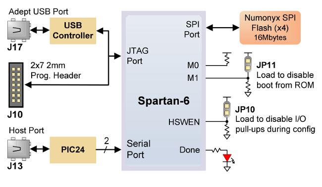
Both Digilent and Xilinx freely distribute software that can be used to program the FPGA and the SPI ROM. Programming files are stored within the FPGA in SRAM-based memory cells. This data defines the FPGA’s logic functions and circuit connections, and it remains valid until it is erased by removing power or asserting the PROG_B input, or until it is overwritten by a new configuration file.
During FPGA programming, a .bit or .svf file is transferred from the PC directly to the FPGA using the USB-JTAG port. When programming the ROM, a .bit, .bin, or .mcs file is transferred to the ROM in a two-step process. First, the FPGA is programmed with a circuit that can program the SPI ROM, and then data is transferred to the ROM via the FPGA circuit (this complexity is hidden and a simple “program ROM” interface is shown). A programming file stored in the SPI ROM will remain until it is overwritten, regardless of power-cycle events.
Adept and iMPACT USB port
The Adept port is compatible with Xilinx's iMPACT programming software if the Digilent Plug-In for Xilinx Tools is installed on the host PC (download it free from the Digilent website’s software section). The plug-in automatically translates iMPACT-generated JTAG commands into formats compatible with the Digilent USB port, providing a seamless programming experience without leaving the Xilinx tool environment. Once the plug-in is installed, the "third party" programming option can be selected from the iMPACT tools menu, and iMPACT will work as if a Xilinx programming cable were being used. All Xilinx tools (iMPACT, ChipScope, EDK, etc.) can work with the plug-in, and they can be used in conjunction with Adept tools (like the power supply monitor).
For more information about installing the Adept plug-in see the FPGA design from scratch blogg ( part 63 ).
Program the SPI flash
We have already seen how we can configure the FPGA using the Xilinx USB cable and the Xilinx configuration tool iMPACT. Now let's see how we can use the same setup to program the SPI flash memory. We will start by loading the FPGA configuration file to the SPI flash.
Generate a bit file for SPI load
We use the makefile found in the backend/par/run directory to generate the bit file using the command: make orpsoc_spiboot.bit. This command will be executed in the makefile:
bitgen -w -intstyle silent -g StartUpClk:CClk orpsoc.ncd orpsoc_spiboot.bit

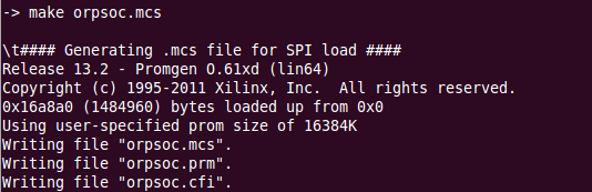
Generate the SPI load file
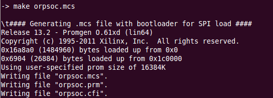
We use the makefile found in the backend/par/run directory to generate the SPI load file using the command: make orpsoc.mcs. This command will be executed in the makefile:
promgen -spi -p mcs -w -o orpsoc.mcs -s 16384 -u 0 orpsoc_spiboot.bit
SPI flash memory on board
The N25Q128 from Numonyx is a 128 Mbit (16Mb x 8) serial Flash memory, with advanced write protection mechanisms. It is accessed by a high speed SPI-compatible bus and features the possibility to work in XIP (“eXecution in Place”) mode. The N25Q128 supports innovative, high-performance quad/dual I/O instructions, these new instructions allow to double or quadruple the transfer bandwidth for read and program operations.
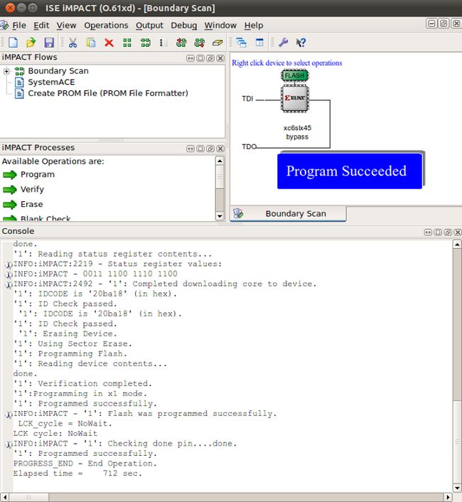
Program the SPI flash
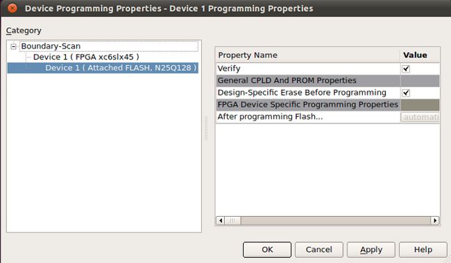
We will use iMPACT and create a new project.
We configure the device using JTAG.
The FPGA is identified and we have the following setup.


The flash programming will take for ever (last time it took 3 hours) so you better leave it overnight to finish. Here is the result. The programming was successful but I couldn't get it to work when using Design Suite 14.2 I had to go back to Design Suite 13.4. I am going to find out why it didn't work by asking around. Will let you know as soon as I have answer.
l
 l
l
Running iMPACT in batch mode
We can save some time by running iMPACT in batch mode. Here is the command file:

Here is the command to start iMPACT: impact -batch impact.cmd
Removing the JP11 jumper
When configuring the FPGA from the SPI flash the JP11 mode jumper must be removed. We find the jumper below the HID host port (USB contact).
Power-on configuration
After the SPI ROM has been programmed, it can automatically configure the FPGA at a subsequent power-on or reset event if the JP11 jumper is removed. A programming file stored in the SPI ROM will remain until it is overwritten, regardless of power-cycle events.
7.Loading and executing a program
Introduction
When have figured out how to program the SPI flash we are ready to load and execute an application program. We will use a simple program to turn on some of the LEDs on the board. We will put the binary code in the SPI flash starting at address 0x1c0000 and let the simple bootloader copy the program to SDRAM and start execution when we power-cycle the board.
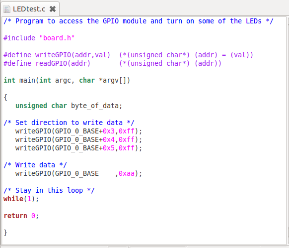
C-program
The c-program looks like this. It will turn on four of the eight LEDs on the board.
Create a board file
We need to creata a board file for the Atlys board. We can download a template file from here and rename it to atlys.S and make the modifications needed. The only thing we will change is the board frequency to 50000000.
/*
* Define symbols to be used during startup - file is linked at compile time
*
*/
.global _board_mem_base
.global _board_mem_size
.global _board_clk_freq
_board_mem_base: .long 0x0
_board_mem_size: .long 0x800000
_board_clk_freq: .long 66666666
/* Peripheral information - Set base to 0 if not present*/
.global _board_uart_base
.global _board_uart_baud
.global _board_uart_IRQ
_board_uart_base: .long 0x90000000
_board_uart_baud: .long 115200
_board_uart_IRQ: .long 2
Compile the board file using this command: or32-elf-gcc -c atlys.S
Archive the compiled file using this commamnd: or32-elf-ar -rs libboard.a atlys.o
Copy the libboard.a to the directory "path_to_toolchain"/or32-elf/lib/boards/atlys

Compiling the program
or32-elf-gcc -mnewlib -mboard=atlys LEDtest.c -o LEDtest.exe
Generate a bin file
Use this command to generate a bin file from the ELF file:
or32-elf-objcopy -O binary LEDtest.exe LEDtest.bin
Adding the size block
Before we can make the SPI flash image file we have to add the size block (the first four bytes) to the binary file. The bootloader reads the size header and understands how many bytes to copy. To our help we have a number of utility programs found in the utils directory:
We use the following command to add the size header:
bin2binsizeword LEDtest.bin LEDtest_sz.bin
Generate the SPI image file
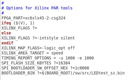
By adding the bin file to the makefile found in the directory: <...../boards/xilinx/atlys/backend/par/bin> we can use a simple make command to generate the orpsoc.mcs file.
Add the following line in the makefile: BOOTLOADER_BIN ?=$(BOARD_ROOT)/sw/src/LEDtest_sz.bin
Executing the program
After loading the SPI image (see previous chapter) and power-cycling the board four of the LEDs light up. Here is the proof.
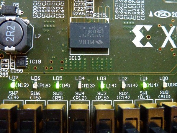
8.Adding a serial terminal
Introduction
We need a solution for communicating with the programs running on our board. We will use the UART implemented in our system for the serial communication. The UART pins are connected to an UART-USB bridge device on the board and then connected to the USB connector.

Free Windows and Linux drivers can be downloaded from www.exar.com. After the drivers are installed, I/O commands from the PC directed to the USB port will produce serial data traffic on the A16 and B16 FPGA pins.
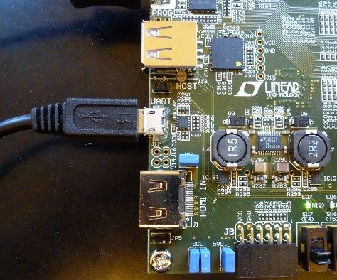
Hardware implementation
This is what the Atlys board implementation looks like:

Downloading and installing Linux drivers
After unzipping, unpacking and running make, the downloaded packages looks like this:
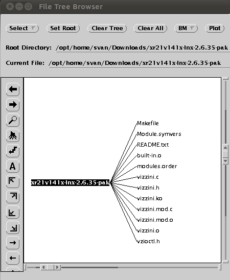
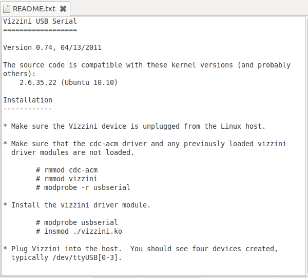
The README.txt file tells us what to do. I found out that I had to redo this settings after i rebooted my system. Can anyone help me to make these settings permanent.
Remove old driver:
cd vizzini_install_dir
sudo rmmod cdc-acm
sudo rmmod vizzini
sudo modprobe -r usbserial
Install the vizzini driver module:
sudo modprobe usbserial
sudo insmod ./vizzini.ko
After installing the driver we can use the command lsusb to see all the USB devices supported.

Removing the USB cable and inserting it again gives the following log messages. Use the command dmesg to display the logfile.

Setting up a serial terminal
We will setup a serial terminal emulator program running in our Linux workstation to emulate the console. We can use for example GTKterm or minicom. GTKterm has a nice GUI which makes it really easy to setup. Let's use GTKterm. For more information about GTKterm read this blog entry.
Using GTKterm
We start the program using the command: gtkterm& and open the Port Configuaration window:
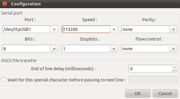
Select the USB port connected to the Atlys board and set the speed to 115200 and we are ready to run. Here is a print out from the PrimeNumbers program executing in the system.
9.Installing U-boot the universal bootloader
Introduction
Now when we can communicate with our board it is high time to install U-boot , the universal bootloader. U-boot is an open source, primary boot loader used in embedded devices. It is available for a number of different computer architectures, including PPC, ARM, MIPS, AVR32, x86, 68k, Nios, OpenRISC and MicroBlaze. U-boot will simplify the loading of programs and help us install Linux one day.
U-boot for OpenRISC
This wiki page explains the OpenRISC implementation of U-boot. We start by downloading the source files from the GIT repository: git clone git://openrisc.net/stefan/u-boot
Here is the installed directory structure:

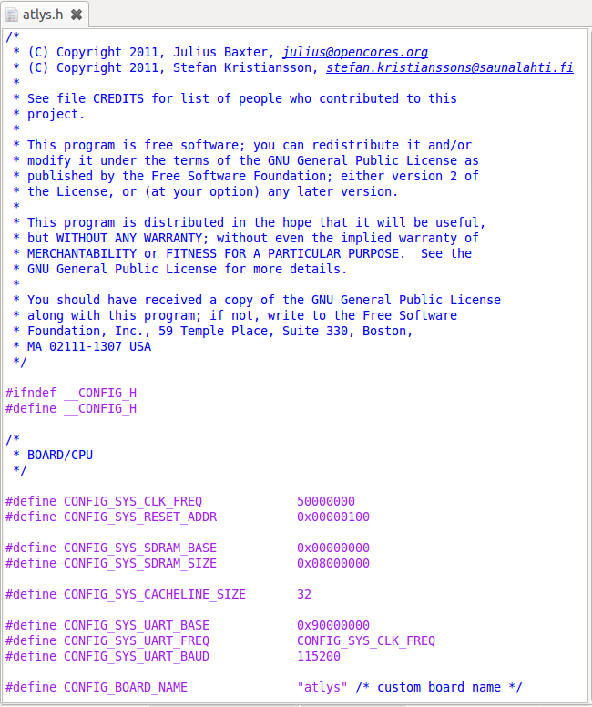
Configuration
There is already a pre-compiled configuration file ready to be used, called atlys.h in the directory: include/configs:
Building the software
Building U-Boot has been tested in several native build environments and in many different cross environments. If we are not using a native environment, it is assumed that we have GNU cross compiling tools available in our path. In this case, we must set the environment variable CROSS_COMPILE in our shell. Note that no changes to the Makefile or any other source files are necessary.
CROSS_COMPILE=or32-elf-
export CROSS_COMPILE
Lets add this line in our .bashrc file: export CROSS_COMPILE=or32-elf-
Next step is to run:
make distclean
make atlys
Converting the image.bin file
We take the generated u-boot.bin file and run it through the same process as we did with the LEDtest.bin file.
U-boot running in the system
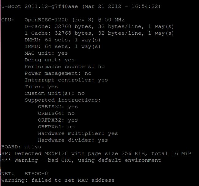
After waiting a few minutes for the image to be programmed to the SPI flash and then moved to the SDRAM and started, this is displayed on the serial terminal. We have U-boot up and running.
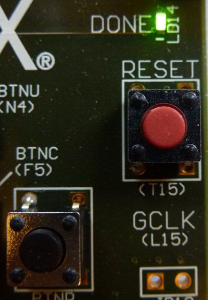
Starting U-boot after power-up
After powering up the board we can restart U-boot by pressing the Reset button.
Setting up the environment
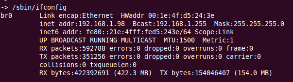
The environment variables are defined from inside the U-boot program. We start by setting the MAC address to some address not used by any other node in the network.
Next step is to set the IP addresses matching the addresses used in our local network. We have to find an IP address for our board not used in our subnet. Here is an example from our installation. After setting the environment variables we us the command saveenv to save all the settings in the SPI flash. We then have to reset our board.

To find the serverip execute the following command on our host:
Using U-boot
Here is a link to the U-boot user's manual. The help command display all the available commands:

10.Using U-boot
Introduction
When we have U-boot running in our system, we get access to many useful commands for transfering images from our host to the Atlys board. For this to work we need a network connection to our host using the local area network and an ethernet connection.
Setting up the ethernet connection
The Atlys board includes a Marvell Alaska Tri-mode PHY 88E1111 paired with a Halo HFJ11-1G01E RJ-45 connector. Both MII and GMII interface modes are supported at 10/100/1000 Mb/s. Default settings used at power-on or reset are:
- MII/GMII mode to copper interface
- Auto Negotiation Enabled, advertising all speeds, preferring Slave
- MDIO interface selected, PHY MDIO address = 00111
- No asymmetric pause, no MAC pause, automatic crossover enabled
- Energy detect on cable disabled (Sleep Mode disabled), interrupt polarity LOW
OpenRISC designs can access the PHY using 10/100Mbps ethernet MAC core for 10/100 Mbps. Observe!! There is no support for 1Gbps.

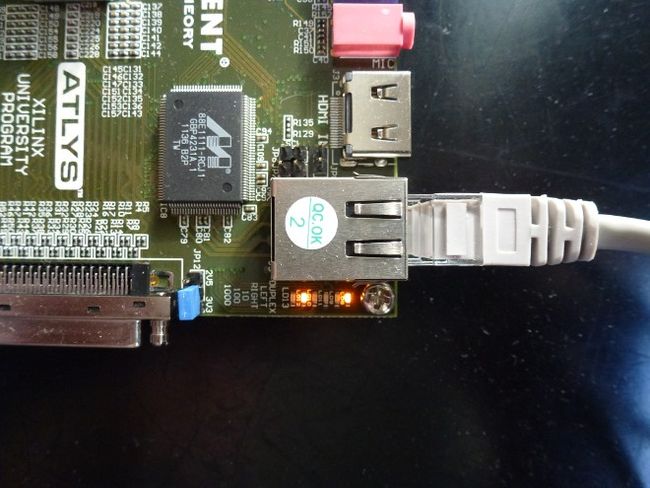
Connecting to the local area network
There are six LEDs on the board indicating the following status:
| LED | Description |
| 0 | Duplex |
| 1 | Transmitt |
| 2 | Receive |
| 3 | Link10 |
| 4 | Link100 |
| 5 | Link1000 |
Networking configuration procedures
To be able to communicate between our board and the host system through the LAN we need to setup different networking procedures. This tutorial will show us how to setup communication channels between U-boot running in the OpenRISC processor and the host system we use for all our program development and hardware generation. We will look at setting up a TFTP server and a NFS server. We will also look at how to use telnet and ftp for communication with our board.
Using the Trivial File Transfer Protocol
Trivial File Transfer Protocol (TFTP) is a file transfer protocol notable for its simplicity. It is generally used for automated transfer of configuration or boot files between machines in a local environment. Compared to FTP, TFTP is extremely limited, providing no authentication, and is rarely used interactively by a user. Due to its simple design, TFTP could be implemented using a very small amount of memory. It is therefore useful for booting computers such as routers which may not have any data storage devices. It is an element of the Preboot Execution Environment (PXE) network boot protocol, where it is implemented in the firmware ROM / NVRAM of the host's network card. We will use tftp for transfering program image files from our server host to the SDRAM in our OpenRISC system using U-boot and then start program execution from U-boot.
Setting up the /tftpboot directory
The tftpboot command always looks for the image file in the host directory /tftpboot. We have to create this directory on our host machine and allow full access (chmod 777). All the images must be copied to this directory before they can be transfered to the Atlys board using the tftpboot command.
Preparing the boot image
There are two types of boot images that can be transfered using the tftpboot command in U-boot. The first is the ELF format. Here is an example. We use the command: bootelf to start the program.

Create a bare metal boot image
To create a u-boot image from a baremetal program in bin format, the u-boot tool <mkimage> is used. It is available in u-boot's tools/ directory and the following command can be used to create a not compressed bare metal image called 'PrimeNumbers' with load address 0 and entry point at 0x100:
or32-elf-objcopy -O binary PrimeNumbers PrimeNumbers.bin
mkimage -A or1k -T standalone -C none -a 0 -e 0x100 -n PrimeNumbers -d PrimeNumbers.bin /tftpboot/PrimeNumbers.ub
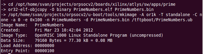
We use the command: tftp PrimeNumbers.ub to transfer the image to the SDRAM on the board. The command: bootm 100000 is used to run the program.

11.Installing Linux
Introduction
The Linux kernel has been ported to the OpenRISC 1000 family. The OpenRISC Linux kernel is a free and open source operating system. Features are:
- Free, open source code with no royalty
- UNIX class operating system
- Process protection through use of the Memory Management Unit
- Multitasking, preemptive scheduling
- Interprocess communication and synchronization
- TCP/IP networking and numerous other network protocols
- File systems NFS, ext2, MS-DOS, FAT16/32 and others
Status
Kernel version is tracking mainline. It is capable of booting and running BusyBox userspace. The C library providing user space support is uClibc .
Download source
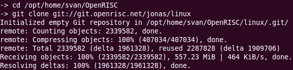
At present the Linux port is maintained by Jonas Bonn of South Pole and kept in their git repositories. To obtain a copy of the kernel tree source with OpenRISC support, ensure git is installed and run:
git clone git://git.openrisc.net/jonas/linux

Setting CROSS_COMPILE
We must set the environment variable CROSS_COMPILE in our shell before starting the Linux kernel build. Lets add this line in our .bashrc file:
export CROSS_COMPILE=or32-elf-
Build the Linux kernel
cd ..../OpenRISC/linux
make defconfig
make


Run the kernel in the simulator
Use the following command to run the Linux kernel in the OpenRISC architectural simulator (or1ksim):
or32-elf-sim -f arch/openrisc/or1ksim.cfg vmlinux
Changing the uart setup
The first time we run the simulator it hangs at the following setup:
 l
l
Changing the UART setup in the or1ksim config file fixes the problem. We add an xterm terminal to be used as input/ouput device.

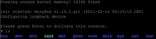
Linux up and running

Installing Linux on the Atlys board
The standard OpenRISC Linux kernel port contains enough to boot the kernel and present the user with a console prompt via the serial port. The following guide uses the Atlys development board as an example target for kernel configuration, compilation and download.
Atlys device tree setup
The Atlys FPGA design has a slightly different configuration than the simulator, which we need to tell the kernel about. Linux represents hardware as a device tree in a .dts file.
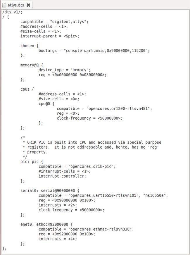
I've created a simple device tree for the Atlys board and put it in the: arch/openrisc/boot/dts/ directory.
 l
l
Compared to the or1ksim.dts, it sets the processor and USART clock speed to the correct 50MHz.
Kernel configuration
We will use the menuconfig tool to configure the kernel for our board.
make menuconfig
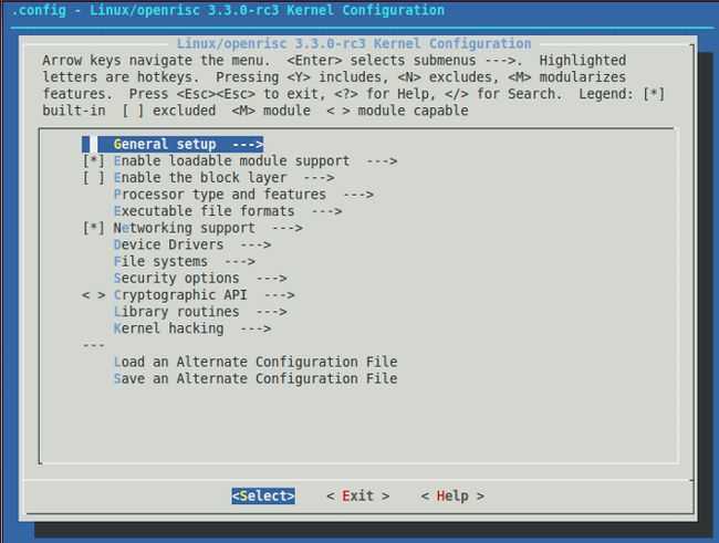
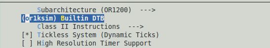
and change or1ksim to atlys.

Generate an downloadable linux image
Use this command to generate an image that can be downloaded from U-boot.
cd ......./orpsocv2/u-boot
./tools/mkimage -n 'Linux for OpenRISC' -A or1k -O linux -T kernel -C none -a 0 -e 0x100 -d /opt/home/svan/OpenRISC/linux/vmlinux.bin /tftpboot/uImage
Download the linux image
From U-boot use the following command to download the Linux image to the SDRAM:
tftp uImage
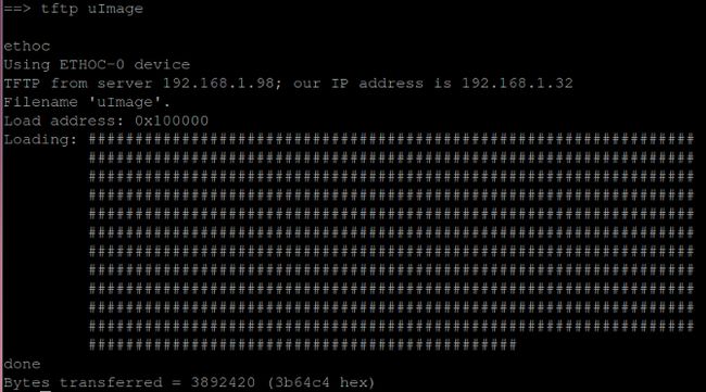
Boot Linux
We are ready to boot linux: bootm 100000
 l
l
A lot of text printed.
Linux version
# more version
Linux version 3.3.0-rc3-10289-g6096074-dirty (svan@Superdatorn) (gcc version 4.5.1-or32-1.0rc4 (OpenRISC 32-bit toolchain for or32-elf (built 20110410)) ) #7 Mon Mar 26 15:25:53 CEST 2012
12.Benchmarking OpenRISC 1200
Introduction
In computing, a benchmark is the act of running a computer program, a set of programs, or other operations, in order to assess the relative performance of an object, normally by running a number of standard tests and trials against it. The term 'benchmark' is also mostly utilized for the purposes of elaborately-designed benchmarking programs themselves.
Benchmarking is usually associated with assessing performance characteristics of computer hardware, for example, the floating point operation performance of a CPU, but there are circumstances when the technique is also applicable to software. Software benchmarks are, for example, run against compilers or database management systems.
CPU core benchmarking
Although it doesn’t reflect how you would use a processor in a real application, sometimes it’s important to isolate the CPU’s core from the other elements of the processor and focus on one key element. For example, you might want to have the ability to ignore memory and I/O effects and focus primarily on the pipeline operation. This is CoreMark’s domain. CoreMark is capable of testing a processor’s basic pipeline structure, as well as the ability to test basic read/write operations, integer operations, and control operations. Read more .
CoreMark
CoreMark is a benchmark that aims to measure the performance of central processing units (CPU) used in embedded systems. It was developed in 2009 by Shay Gal-On at EEMBC and is intended to become an industry standard, replacing the antiquated Dhrystone benchmark. The code is written in C code and contains implementations of the following algorithms: list processing (find and sort), Matrix (mathematics) manipulation (common matrix operations), state machine (determine if an input stream contains valid numbers), and CRC. Read more .
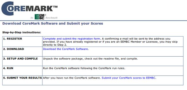
Downloading CoreMark
The test suite can be downloaded from www.coremark.org
After downloading and unpacking we have the following directory structure.
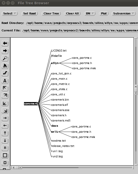
We will add two port directories called or1k and atlys. In these directories we put three files modified for our design. The files in the or1k directory will be used when compiling CoreMark for running in the simulator and the files in the atlys directory will be used when compiling for the Atlys board.
Compiler optimization
Without any optimization option, the compiler's goal is to reduce the cost of compilation and to make debugging produce the expected results. Statements are independent: if you stop the program with a breakpoint between statements, you can then assign a new value to any variable or change the program counter to any other statement in the function and get exactly the results you would expect from the source code.
Turning on optimization flags makes the compiler attempt to improve the performance and/or code size at the expense of compilation time and possibly the ability to debug the program. The compiler performs optimization based on the knowledge it has of the program. Compiling multiple files at once to a single output file mode allows the compiler to use information gained from all of the files when compiling each of them. Here is a link to a page describing possible optimization options. Depending on the compiler options we choose the benchmark result may vary. When comparing different processors it is important we use the same compiler options to get reliable results.
The port directory
The port directory contains three files that are modified for the processor we are going to benchmark:
core_portme.c
core_portme.h
core_portme.mak
New GNU toolchain
The first thing I had to do was asking Julius for an updated GNU toolchain. The 1.0rc1 precompiled version I had didn't let me compile and run the CoreMark benchmark. Julius compiled a new toolchain from the OpenCores SVN repository revision 789. He promised to put it on the OpenCores FTP site. Here is a link to download the latest version.
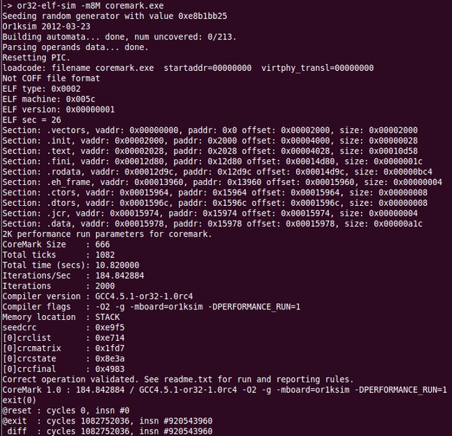
Compiling for the simulator
The following commands are used to compile the benchmark for running in the OR1K simulator:
cd ..../coremark
make PORT_DIR=or1k ITERATIONS=2000
When changing number of iterations use the following command:
make PORT_DIR=or1k ITERATIONS=4000 REBUILD=1

Use this command to start the simulator:
or32-elf-sim -m8M coremark.exe
Compiling for the board
The following commands are used to compile the benchmark for running on the Atlys board:
cd ..../coremark
make PORT_DIR=atlys ITERATIONS=2000
Create a bare metal boot image
To create a u-boot image from a baremetal program in bin format, the u-boot tool <mkimage> is used. It is available in u-boot's tools/ directory and the following command can be used to create a not compressed bare metal image called 'coremark' with load address 0 and entry point at 0x100:
or32-elf-objcopy -O binary coremark.exe coremark.bin
mkimage -A or1k -T standalone -C none -a 0 -e 0x100 -n coremark -d coremark.bin /tftpboot/coremark.ub
Benchmark conditions
Here are the conditions during the benchmark.
| Condition | Value |
| Development board | Digilent Atlys Xilinx University Program |
| FPGA | Xilinx Spartan-6 XC6LX45CSG324C |
| Processor clock | 50 MHz |
| Instruction cache | 32 KB |
| Data cache | 32 KB |
| MMU | Yes |
| Hardware multiply | Yes |
| Hardware divide | Yes |
| Floating point | Single precision |
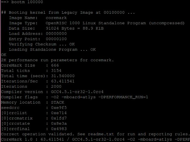
Running on the board
Here is the result from running CoreMark on the Atlys board. Observe that no compiler optimization (except for -O2) has been used.
tftp coremark.ub
bootm 100000
Optimization experiments
Here are the results from trying to optimize the compilation phase. Without any optimization at all :
0.35 CoreMark/MHz
| Compiler Option | -O2 | -O3 |
| No extra | 1.27 | 1.31 |
| -mhard-div -mhard-mul | 1.27 | 1.31 |
| -funroll-loops | 1.39 | 1.36 |
| -fgcse-sm | 1.28 | 1.32 |
| -msoft-float | 1.27 | 1.31 |
| -funroll-all-loops | 1.41 | 1.38 |
| All | 1.41 | 1.38 |
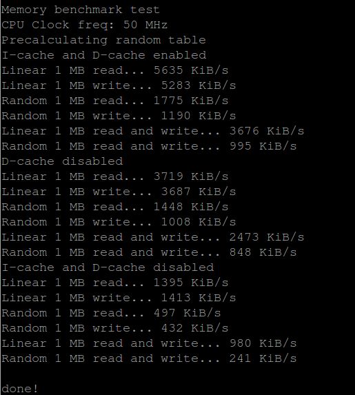
Memory system benchmark
The CoreMark benchmark is setup to mainly test the processor part of our system. Stefan Kristiansson has written a testbench to test the efficiency of the memory system which can be downloaded from his GIT repository using the following command:
git clone git://git.chokladfabriken.org/membenchmark
After downloading the files (main.c and makefile) we use the following command to compile and make a bin file for loading into our system.
make BOARD=atlys
Here is the result from running the program on our Atlys board.
13.Debugging the OpenRISC 1200
Introduction
There are different ways of performing debugging depending on the "target" (the actual representation of the OpenRISC processor and platform.) Two main categories of target exist; physical targets such as FPGA or ASIC OpenRISC implementations, and simulated targets such as a low-level event-driven simulations of RTL models (using a simulator such as Icarus Verilog) or models with greater abstraction such as the OR1ksim architectural simulator.
We will focus on debugging with the GNU debugger , GDB, as the primary user interface. The "targets" that GDB connects to will somehow support GDB with a "stub" or a component that can understand and translate GDB commands into the appropriate commands for the target. Here is some more information about using gdb for software debugging.
The four currently supported targets for debugging are:
- Physical target (FPGA or ASIC)
- Event-driven simulation
- Cycle-accurate model simulation
- Architectural simulator
Debugging a physical target
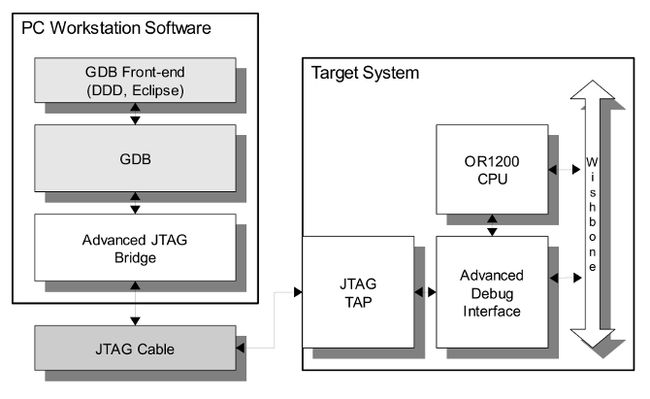
Physical implementations of OpenRISC systems can be debugged using a set of tools made available at OpenCores.org . Whether simply poking registers in IP cores or debugging complex software executing on the processor, these tools provide a useful debugging capability. The following block diagram gives a simplistic representation of the of the components involved in debugging a physical target.
JTAG TAP
The implementation of the Test Access Port (TAP) is fully IEEE 1149.1 compliant. It includes a TAP controller, a 4-bit instruction register and three test data registers: idcode register, bypass register and boundary scan register.
SoC debug interface
The Debug Interface is used for development purposes (debugging). It is an interface between the CPU(s), peripheral cores and any commercial debugger/emulator. The external debugger or BS tester connects to the core via JTAG port that is fully IEEE 1149.1 compatible. For that reason JTAG TAP needs to be used together with this core.
The GNU debugger
The GNU debugger, GDB, is a popular tool that is capable of debugging many architectures from many platforms. The OpenRISC port of GDB (or32-elf-gdb), is used as the primary debugging tool for all OpenRISC targets. It functions as, among other things, the actual user interface when debugging.
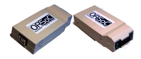
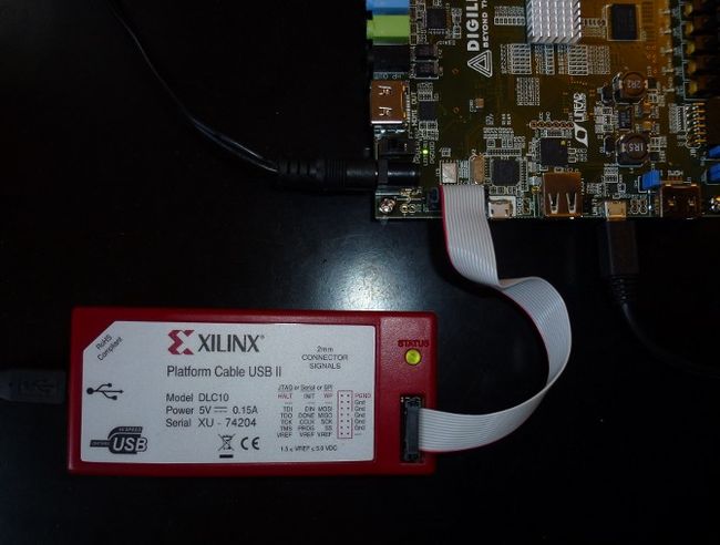
Using the ORSoC USB to JTAG debugger
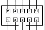
ORSoC has developed an USB to JTAG debugger , aimed at debugging OpenRISC based systems. One or more OpenRISC processors can be controlled over a JTAG interface. Additionally the debugger could be used to handle a serial connection for a console. Signal level on the JTAG is user configurable by use of an external voltage. The debugger is USB 1.1 compatible for easy connection to a host. A local proxy server handles the USB connection and offers a TCP connection to a software debugger. The GNU debugger with optional graphical user interface, such as DDD, is supported. It connects to the board under test with a ribbon cable. The cable has a 2×5 pin header with 0,1″ spacing using the following pinout:
| Pin | Connects To | Description |
| 1 | JTAG TCK | JTAG Test Clock |
| 2 | GND | Ground |
| 3 | JTAG TDO | JTAG Test Data Out |
| 4 | VCCIO JTAG | External Reference Voltage JTAG Port |
| 5 | JTAG TMS | JTAG Test Mode Select |
| 6 | VCCIO UART | External Reference Voltage UART |
| 7 | UART RX | UART Receive |
| 8 | UART TX | UART Transmitt |
| 9 | JTAG TDI | JTAG Test Data Input |
| 10 | GND | Ground |
Contact pin numbering
Connecting to the Atlys board
We will use the available Pmod connector on the Atlys board to connect the USB-JTAG debugger cable.The Pmod connector is a 2x6 right-angle, 100-mil female connector that mates with standard 2x6 pin headers available from a variety of catalog distributors. The 12-pin Pmod connector provides two VCC signals (pins 6 and 12), two Ground signals (pins 5 and 11), and eight logic signals. VCC and Ground pins can deliver up to 1A of current. Jumper JP12 selects the Pmod Vcc voltage (3.3V or 2.5V) in addition to selecting the VHDC voltage. Pmod data signals are not matched pairs, and they are routed using best-available tracks without impedance control or delay matching.
From the schematics.
Connecting the JTAG port to the Pmod connector
To physically connect the JTAG module input and output pins to the Pmod connector we will modify the atlys.ucf file. From the file orsoc_top.v we can find out the port names of the JTAG module.

Here is the modified atlys.ucf file. We put the TCK clock on a clock input pin (JA-CLK-P).
Reduild the design
We will rerun the complete design flow after the changes we have made. See: Using ORPSoC. Just remember to run: <make clean> before the new make commands.
Pmod to FPGA to JTAG debugger
The Pmod connector is connected to the follow pins on the Spartan-6 FPGA and the JTAG debugger.
| Pmod Connector | FPGA pin | JTAG Debugger |
| JA1 | T3 | 3 TDO |
| JA2 | R3 | 5 TMS |
| JA3 | P6 | 9 TDI |
| JA4 | N5 | |
| JA5 GND | 2 GND | |
| JA6 VCC | 4 VCC | |
| JA7 | V9 | |
| JA8 | T9 | 1 TCK |
| JA9 | V4 | |
| JA10 | T4 | |
| JA11 GND | ||
| JA12 VCC |
Building a connection board
We need to build a small board to connect the USB-JTAG ribbon cable to the Pmod contact. It looks like this:
The debug proxy
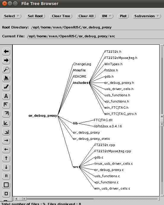
The debug proxy controls the link between GDB and the physical target. It implements a GDB stub, and provides support for most GDB commands. Physical connection to the board is made with the use of a USB debug cable. The ORSoC USB Debug Cable is one supported USB cable but there are other solutions. The proxy first establishes a connection with the target and stalls the processor. Next it waits for a connection with GDB via network sockets, and then begins translating received GDB commands into JTAG transactions with the debug interface via the USB cable. Transactions such as reading and writing registers, or downloading executables to memory are done through this interface. The OpenRISC Debug Proxy (or_debug_proxy) can be downloaded from the OpenRISC project's subversion repository using the following command:
svn co http://opencores.org/ocsvn/openrisc/openrisc/trunk/or_debug_proxy
The README included with the source provides detailed installation and usage instructions but a brief step-by-step guide for installation and compilation under Linux.
We can use a simple make to compile the program (or_debug_proxy). Before we compile the program we have to make sure the lftd2xx library is available. For more information read the README file.
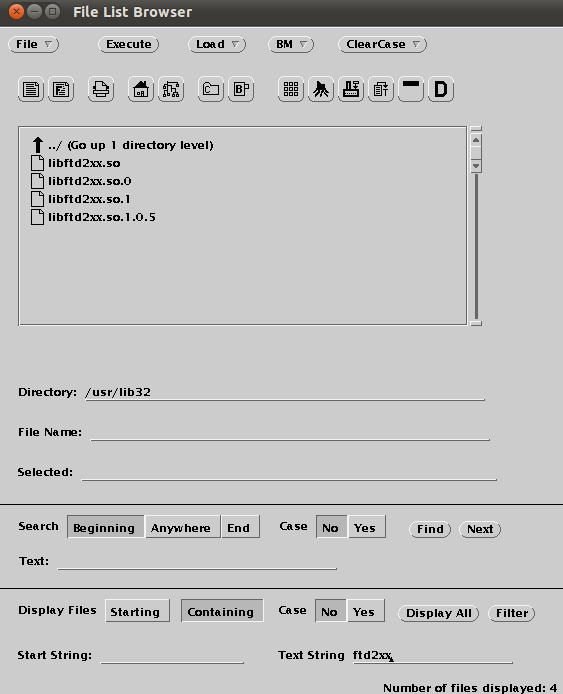
Downloading FTD2xx library
After failing to connect to the board I found out that the new version FTD2XX (1.0.5) did not work together with the or_debug_proxy. We have to download the old library (0.4.16) from the FTDI web page.
Compiling OpenRISC Debug Proxy
There are two ways to compile the proxy - one linked to the dynamic library, and one linked to the static library. There is no difference in performance or functionality, it is a little easier to compile against the static library as there are more steps involved to install the dynamic library. To compile the proxy application against the static library, simply go into the source directory and run a "make static", note that this requires the static driver library is located in the lib/ directory in the proxy source code.
Here are all the files involved.
Installation
The OR debug proxy application runs on multiple platforms only requiring slightly different driver configurations on each. Currently, Cygwin Windows, several Linux distros and Mac OS X (10.4 and above) are supported. Use with the ORSoC debug cable requires installation of some form of the FTDI Chip FTD2XX driver. It is required that the Linux distribution have a version 2.4 kernel, or above. This is due to the USB driver libraries by FTDI Chip used to interface with the USB debug device..
These USB to serial devices typically trigger the loading of another FTDI driver when they're attached to the system. This is the ftdi_sio driver and now comes standard in newer kernels. This is of use to us, as one of the two serial devices will remain is a standard UART under /dev/ttyUSBx. However, to enable a high-speed JTAG interface with our hardware we require newer, specialised drivers from FTDI called the D2XX drivers. As seen above they are already installed in our system.
ORSoC USB debug cable device permissions
To avoid having to run the proxy with sudo or as root user, permissions on the USB should be set permitting regular users access to the device. An example of setting the permissions on recent udev systems (almost all 2.6 kernel distributions use udev) is presented here. The ORSoC USB debug cable is identified from its USB vendor and product IDs (0x0403 and 0x6010, respectively) by the system when it is connected. Use the command lsusb to locate the connected USB-JTAG Debugger (Bus 005 Device 015).
We can insert a rule which allows user read and write permissions on this device when it is connected.This rule should be inserted in a file in the udev rules directory, /etc/udev/rules.d. It is easiest to create a new file, called 90-permissions.rules in the udev rules directory, which should contain the following:

Test this rule by unplugging and reconnecting the USB debug cable, and looking at the permissions of the two /dev/ttyUSB devices. The permissions should look like the following when listed with ls -l:
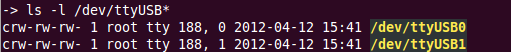
If the permissions do not have rw- in the final three characters, then the user is not able to access it. It is possible the rules file was not setup properly. Check the README for solutions to setting permissions on the cable for other platforms.
The final setup
Here is what the debug solution looks like.

Connecting to the target
Once the tools are setup, a connection to the system must be established. This connection occurs in two steps. The first step is to establish the connection between the proxy and the JTAG tap controller via the USB debug cable. Next, GDB connects to the proxy, and the debugging session can begin.
Connecting the proxy to the target
Connecting the proxy to the target is the first step to setting up the debugging chain. The proxy attempts to create the connection automatically when it is run. When the proxy is launched it automatically performs some actions, these are: reading of the JTAG TAP controller ID and check it's sensible, set the TAP to debug mode, stall the CPU, read back a few registers (PC, NPC, GPR1), and finally open a socket for the connection from GDB. The port for GDB to connect to is specified on the command line when launching the proxy with the -r option. In the following example port 55555 is used.
./or_debug_proxy -r 55555
Because we haven't connect the JTAG debugger to the Atlys board we get the following error message:
We will figure out how to connect to the board and make the small connection board. Is is fixed now. We have a debug connection with the Atlys board.
Connecting GDB to target
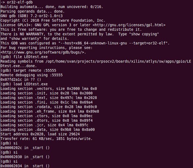
Once the proxy is running, the next step is connecting to the proxy from GNU Debugger GDB (or32-elf-gdb). Since GDB 6.8, communication between the proxy and GDB uses the remote serial protocol (RSP). The following commands show an example of starting GDB and connecting to the proxy. If the proxy is running on the same machine as GDB is being run on, then the following commands will work, otherwise substitute the IP of the machine running the proxy for localhost:
or32-elf-gdb
target remote localhost:55555
Compiling program for debugging
Use this command to compile the LEDtest.c program for debugging (-g option to generate debug information) :
or32-elf-gcc -g mboard=atlys LEDtest.c -o LEDtest.elf
Loading and running a program
Here are the commands to load and run a C-program (LEDtest.elf) from GDB.
file LEDtest.elf (Load symbol table)
load (Load program to target)
c (run program)

GDB connecting through RSP with target remote is connecting to a target which is already executing, but has stalled. Thus it is inappropriate to use the run command (which specifies a new program to run). Instead the continue and step commands are used. The load command will reset the program counter to the entry point of the program. So a subsequent continue will cause the newly loaded program to execute from its entry point.
Debugging OpenRISC with gdb
The document: "Debugging with gdb: the gnu Source-Level Debugger for gdb" can be read here.
The people at Embecosm Limited has written a manual called "Debugging the OpenRISC 1000 with GDB". This manual describes how to use GDB to debug C programs cross compiled for and running on processors using the OpenRISC 1000 architecture. In addition the info command is extended to allow inspection of OpenRISC 1000 Special Purpose registers, and a new command “spr” is added to set the value of a Special Purpose Register. See section OpenRISC 1000 Specific Commands.
All the normal GDB commands should work, although hardware watchpoints are not tested at present. The info registers command will show the 32 general purpose registers, while the info registers all command will add the program counter, supervision register and exception program counter registe For those who like their debugging graphical, the gdbtui command is available (or32-elf-gdbtui). GDB for OpenRISC 1000 can also be run under DDD as follows: ddd --debugger or32-elf-gdb
Debugging examples
Loading a program (LEDtest.exe) and single stepping the code:
Displaying all the CPU's special purpose registers: info spr sys
Using Data Display Debugger DDD
DDD is a graphical front-end for command-line debuggers such as GDB, DBX, WDB, Ladebug, JDB, XDB, the Perl debugger, the bash debugger, or the Python debugger. DDD displays data structures as graphs and plots.Here is the User's Manual.
OpenOCD
OpenOCD is a program that we can use to talk to our debug interface on our hardware via JTAG, over a variety of cables, in a realtively flexible manner. We can script up things in TCL to control the system, or we can run a GDB RSP server and do things from GDB. OpenOCD will replace or_debug_proxy as the future debug interface.
The OpenOCD code with basic OpenRISC 1000 support is found on the openrisc.net git tree: git clone git://openrisc.net/julius/openocd
Using the advanced debug interface
There is also another solution available for debugging our board. It is called the advanced debug interface. To use this interface we have to modify our SOC design.
Connecting to the Atlys board
I don't have a solution today. If someone can provide me with one I would be more than happy. Can we use this box together with the Advanced Debug System?
We will find out next week. While we are waiting we can study the document " Debugging System for OpenRISC 1000-based Systems" written by Nathan Yawn.
14.Using orbuild
Introduction
The OpenRISC project has grown and is now made up of many different components that need to be separately downloaded, configured and built. To many people, all these manual steps are a hassle, they just want to use the processor in their FPGA designs and have no interest in the supporting tools and technologies.
Orbuild is designed to automate this initial setup steps. It has been put together by R. Diez and can be downloaded from the GIT hub: https://github.com/rdiez/orbuild .
Orbuild is not meant to be mandatory, it is just a helping hand which only performs standard downloads and software builds. Users and developers are or course free to ignore it and manually perform the installation and test steps. In the OpenRISC development community there is also the need to run a daily build with many possible component configurations, in order to alert the developers early when something has broken. This is in fact the main reason why orbuild was developed, and the first task it was actually used for. The daily build can also take on the job of generating software releases, as manual release procedures often result in human error.
Prerequisites
orbuild runs on Unix-like systems as well as in the Cygwin environment on Microsoft Windows. However, the most thoroughly tested platform is Linux. Each orbuild project has its own prerequisites. For the OpenRISC project, look at the file: Scripts/Projects/OpenRISC/README.pod.
For Ubuntu/Debian systems, the following commands installs all prerequisites:
sudo apt-get install autoconf
sudo apt-get install bison
sudo apt-get install curl
sudo apt-get install dejagnu
sudo apt-get install flex
sudo apt-get install gcc
sudo apt-get install g++
sudo apt-get install git
sudo apt-get install git-core
sudo apt-get install gperf
sudo apt-get install gxmessage
sudo apt-get install iverilog
sudo apt-get install libmpfr-dev
sudo apt-get install libmpc-dev
sudo apt-get install libncurses-dev
sudo apt-get install libnotify-bin
sudo apt-get install libtool
sudo apt-get install libxml-parser-perl
sudo apt-get install libzip-dev
sudo apt-get install make
sudo apt-get install patch
sudo apt-get install perl
sudo apt-get install subversion
sudo apt-get install tcl-dev
sudo apt-get install texinfo
sudo apt-get install texlive
sudo apt-get install tk-dev
sudo apt-get install verilator
sudo apt-get install xdg-utils
Getting help
Here is the README file.
Trying it out
I think this is a great way to simplify the build and installation of the software needed to use the OpenRISC processor. Let's give it a try. We will download and install the script environment in our Ubuntu 64 bit Linux.
Download from the GIT repository
Use this command to download all the scripts from the GIT repository:
git clone git://github.com/rdiez/orbuild.git

Edit the config file

Starting the build process
Use the command ./orbuild to start the build. During the build we have to enter username and password to the OpenCores repository. When the build process runs successfully this is the result. We have a complete toolchain running on Ubuntu 10.04 64 bit. I have also installed the GNU toolchain in Ubuntu 12.04 32bit without problems.

Installation report
When the installation has finished we get this nice report in html format.

Using the toolchain
We will start by adding the Atlys board to the board library.
Adding bin directory to PATH
Add the the bin directory to the PATH variable.
PATH=/opt/home/svan/OpenRISC/orbuild_12_04/Builds/build-2012-04-16/ToolchainOr32/bin:$PATH
Compiling a c-program
Use this command to compile the LEDtest program.
or32-elf-gcc -mboard=atlys LEDtest.c -o LEDtest.exe
Thanks to Ruben
You have done a great job in simplifying the installation process.
15.eCos real time operating system
Introduction
eCos (embedded configurable operating system) is a free and open source real-time operating system intended for embedded systems and applications which need only one process with multiple threads. It is designed to be customizable to precise application requirements of run-time performance and hardware needs. It is implemented in C/C++ and has compatibility layers and APIs for POSIX and µITRON.
Can we use eCos in our system? Let's find out. We will start by studying the eCos home page .
Information about eCos
Here are some links:
- eCosCentric
- eCos Porting Guide
- eCos Reference Manual
- Open Embedded Technologies
eCos on OpenRISC
OpenRISC is not mentioned on the eCos home page but I know about one company which has made a great effort in updating the eCos port for OpenRISC and that is Ant Micro. Here is what they say on their home page:
"We updated the port to eCos 3.0, fixed what was broken and run it on the OpenRISC development board when it became available to verify that it is functional. The port can now be grabbed from the OpenCores website, and Ant Micro is its official maintainer, with Piotr Skrzypek as the responsible person".
Getting eCos
eCos is hosted on OpenCores SVN. Use this command to download the complete package:
svn co http://opencores.org/ocsvn/openrisc/openrisc/trunk/rtos/ecos-3.0


Here are the installed files.

Installing eCos
eCos uses two tools to build and configure the system: configtool and ecosconfig. ecosconfig is a handy command line program that allows to select the desired eCos target and packages. configtool is a windowed application that provides a clear and intuitive environment to adjust all of the possible configuration options.
eCos configuration tools
The eCos configuration tools are maintained by eCosCentric and can be downloaded from their web page. The pre-built binary of configtool can be downloaded using the following command:
wget http://www.ecoscentric.com/snapshots/configtool-100305.bz2
Unpack and copy to /usr/local/bin directory.
bunzip2 configtool-100305.bz2
chmod 755 configtool-100305
sudo cp configtool-100305 /usr/local/bin/.
sudo ln -s /usr/local/bin/configtool-100305 /usr/local/bin/configtool
Building ecosconfig
ecosconfig needs to be built from scratch. In order to build ecosconfig, go to the ecos-3.0 directory downloaded from SVN. Execute the following command:
./host/configure
The execution stops after a few seconds showing this error messsage.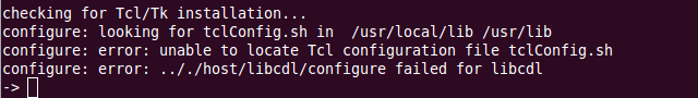
Fixing the tcl/tk installation
We will start by adding the following packages:
sudo apt-get install tcl8.4-dev
sudo apt-get install tk8.4-dev
The configure script looks for the tclConfig.sh and tkConfig.sh files in the directory /usr/local/lib. Let's copy the files to this directory and rerun the script.
sudo cp /usr/lib64/tcl8.4/tclConfig.sh /usr/local/lib/.
sudo cp /usr/lib64/tk8.4/tkConfig.sh /usr/local/lib/.
This time the configuration script finishes without errors. We are ready to build the ecosconfig tool.
make
sudo make install
Both ecosconfig and configtool require environmental variable ECOS_REPOSITORY. The variable must point to the packages directory, inside ecos-3.0 tree. We will add this line in our .bashrc file:
export ECOS_REPOSITORY=/opt/home/svan/OpenRISC/ecos/ecos-3.0/packages
Configuring eCos for OpenRISC
Create a directory to build the eCos library. First start with the default template:
ecosconfig new orpsoc
The default configuration fits the ORPSoC port for ordb2 reference platform. It assumes that hardware multiplication and division are implemented. Floating point variables are handled by software. System clock runs at 50 MHz. If we are using MinSoC, or ORPSoC with different configuation, we need to alter the settings:
configtool ecos.ecc

Let's take a look at the current setup.


We will not make any changes for the Atlys board so we can just save the ecc file. It is always a good idea to check for possible conflicts by running:
ecosconfig check

Building eCos with tests
ecosconfig tree
make
make tests
Writing programs with eCos
It is now possible to write programs linked with eCos. The most simple hello world program (hello.c) would look like this:
#include <stdio.h>
int main(void) {
printf("Hello, eCos world!\n");
return 0;
}
To compile the program, use gcc with the following flags:
or32-elf-gcc \
-g \
-O2 \
-nostdlib \
-install/include \
-Linstall/lib \
-Tinstall/lib/target.ld \
examples/hello.c -o hello.elf
Connecting a serial terminal
We are ready to load and run the Hello World program but before we do we have to connect a serial terminal to see the output from the program. For more information about connecting a serial terminal see this chapter in the blog. We use gtkterm with the following setup.
Running eCos on the Atlys board
The most convenient way is to run the program using GDB debugger. First, start or_debug_proxy:
./or_debug_proxy -r 50001

In another terminal start the GDB debugger.
or32-elf-gdb hello.elf
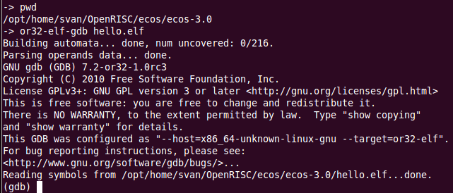
Connect to the target and load and run the program.
target remote :50001
load
c

Output on the serial terminal.

More examples
The Hello World program is not the most interesting program to run in a real time operating system. There are some more programs found in the examples directory.
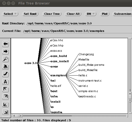
Here is a printout from the twothreads program.