linux下spi驱动分析
一、概述
基于子系统去开发驱动程序已经是linux内核中普遍的做法了。前面写过基于I2C子系统的驱动开发。本文介绍另外一种常用总线SPI的开发方法。SPI子系统的开发和I2C有很多的相似性,大家可以对比学习。
二、SPI总线协议简介
介绍驱动开发前,需要先熟悉下SPI通讯协议中的几个关键的地方,后面在编写驱动时,需要考虑相关因素。
SPI总线由MISO(串行数据输入)、MOSI(串行数据输出)、SCK(串行移位时钟)、CS(使能信号)4个信号线组成。如FS_S5PC100上的M25P10芯片接线为:
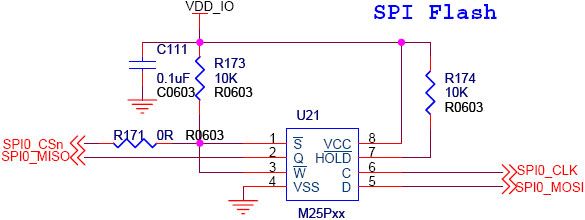
上图中M25P10的D脚为它的数据输入脚,Q为数据输出脚,C为时钟脚。
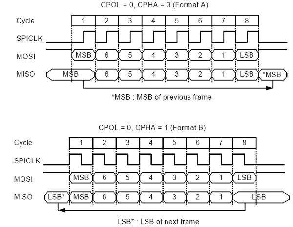
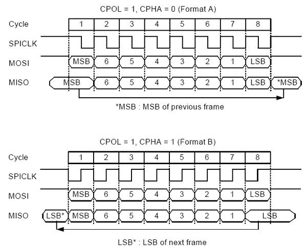
SPI常用四种数据传输模式,主要差别在于:输出串行同步时钟极性(CPOL)和相位(CPHA)可以进行配置。如果CPOL= 0,串行同步时钟的空闲状态为低电平;如果CPOL= 1,串行同步时钟的空闲状态为高电平。如果CPHA= 0,在串行同步时钟的前沿(上升或下降)数据被采样;如果CPHA = 1,在串行同步时钟的后沿(上升或下降)数据被采样。
三、linux下SPI驱动开发
首先明确SPI驱动层次,如下图:
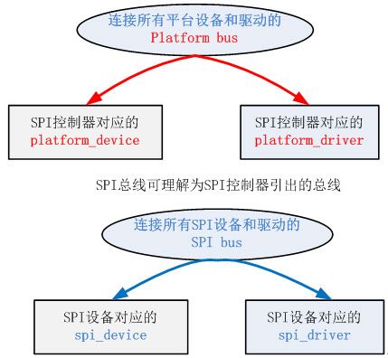
我们以上面的这个图为思路
1、 Platform bus
Platform bus对应的结构是platform_bus_type,这个内核开始就定义好的。我们不需要定义。在文件/include/linux/device.h中
2、Platform_device
SPI控制器对应platform_device的定义方式,platform_device与i2c总线使用的是同一个定义
struct platform_device {
const char * name;
int id;
struct device dev;
u32 num_resources;
struct resource * resource;
const struct platform_device_id *id_entry;
/* MFD cell pointer */
struct mfd_cell *mfd_cell;
/* arch specific additions */
struct pdev_archdata archdata;
};
和I2C类似,SPI也有一个描述控制器的对象叫spi_master。其主要成员是主机控制器的序号(系统中可能存在多个SPI主机控制器)、片选数量、SPI模式和时钟设置用到的函数、数据传输用到的函数等。
struct spi_master {
struct device dev;
s16 bus_num; //表示是SPI主机控制器的编号。由平台代码决定
u16 num_chipselect; //控制器支持的片选数量,即能支持多少个spi设备
int (*setup)(struct spi_device *spi); //针对设备设置SPI的工作时钟及数据传输模式等。在spi_add_device函数中调用。
int (*transfer)(struct spi_device *spi,
struct spi_message *mesg); //实现数据的双向传输,可能会睡眠
void (*cleanup)(struct spi_device *spi); //注销时调用
};
3、Platform_driver
再看platform_driver,参看drivers/spi/spi-omap2-mcspi.c文件
static struct platform_driver omap2_mcspi_driver = {
.driver = {
.name = "omap2_mcspi",
.owner = THIS_MODULE,
.pm = &omap2_mcspi_pm_ops
},
.remove = __exit_p(omap2_mcspi_remove),
};
platform_driver_probe(&omap2_mcspi_driver, omap2_mcspi_probe);;//注册omap2_mcspi_driver
和平台中注册的platform_device匹配后,调用omap2_mcspi_probe。然后根据传入的platform_device参数,构建一个用于描述SPI控制器的结构体spi_master,并注册。spi_register_master(master)。后续注册的spi_device需要选定自己的spi_master,并利用spi_master提供的传输功能传输spi数据。
4、Spi bus
Spi总线对应的总线类型为spi_bus_type,在内核的drivers/spi/spi.c中定义
struct bus_type spi_bus_type = {
.name = "spi",
.dev_attrs = spi_dev_attrs,
.match = spi_match_device,
.uevent = spi_uevent,
.suspend = spi_suspend,
.resume = spi_resume,
};
对应的匹配规则是(高版本中的匹配规则会稍有变化,引入了id_table,可以匹配多个spi设备名称)
static int spi_match_device(struct device *dev, struct device_driver *drv)
{
const struct spi_device *spi = to_spi_device(dev);
const struct spi_driver *sdrv = to_spi_driver(drv);
/* Attempt an OF style match */
if (of_driver_match_device(dev, drv))
return 1;
if (sdrv->id_table)
return !!spi_match_id(sdrv->id_table, spi);
return strcmp(spi->modalias, drv->name) == 0;
}
5、spi_device
下面该讲到spi_device的构建与注册了。spi_device对应的含义是挂接在spi总线上的一个设备,所以描述它的时候应该明确它自身的设备特性、传输要求、及挂接在哪个总线上。
static struct omap2_mcspi_device_config ads7846_mcspi_config = {
.turbo_mode = 0,
.single_channel = 1, /* 0: slave, 1: master */
};
static int ads7846_get_pendown_state(void)
{
return !gpio_get_value(PANDABOARD_TS_GPIO);
}
struct ads7846_platform_data ads7846_config = {
.x_max = 0xFFF,
.y_max = 0xFFF,
.x_plate_ohms = 180,
.pressure_max = 255,
.debounce_max = 10,
.debounce_tol = 3,
.debounce_rep = 1,
.get_pendown_state = ads7846_get_pendown_state,
.keep_vref_on = 1,
//.settle_delay_usecs = 150,
.wakeup = true,
};
struct spi_board_info pandaboard_spi_board_info[] = {
[0] = {
.modalias = "ads7846",
.bus_num = 1,
.chip_select = 0,
.max_speed_hz = 1500000,
.controller_data = &ads7846_mcspi_config,
.irq = OMAP_GPIO_IRQ(PANDABOARD_TS_GPIO),
.platform_data = &ads7846_config,
},
};
static void ads7846_dev_init(void)
{
printk("Initialize ads7846 touch screen controller\n");
if (gpio_request(PANDABOARD_TS_GPIO, "ADS7846 pendown") < 0)
printk(KERN_ERR "can't get ads7846 pen down GPIO\n");
gpio_direction_input(PANDABOARD_TS_GPIO);
gpio_set_debounce(PANDABOARD_TS_GPIO, 1);
}
spi_register_board_info(pandaboard_spi_board_info, ARRAY_SIZE(pandaboard_spi_board_info));//注册spi_board_info。这个代码会把spi_board_info注册要链表board_list上。
事实上上文提到的spi_master的注册会在spi_register_board_info之后,spi_master注册的过程中会调用scan_boardinfo扫描board_list,找到挂接在它上面的spi设备,然后创建并注册spi_device。
static void scan_boardinfo(struct spi_master *master)
{
struct boardinfo *bi;
mutex_lock(&board_lock);
list_for_each_entry(bi, &board_list, list) {
struct spi_board_info *chip = bi->board_info;
unsigned n;
for (n = bi->n_board_info; n > 0; n--, chip++) {
if (chip->bus_num != master->bus_num)
continue;
/* NOTE: this relies on spi_new_device to
* issue diagnostics when given bogus inputs
*/
(void) spi_new_device(master, chip); //创建并注册了spi_device
}
}
mutex_unlock(&board_lock);
}
6、spi_driver
以linux内核中的/driver/input/screen/ads7846.c驱动为参考。
static struct spi_driver ads7846_driver = {
.driver = {
.name = "ads7846",
.bus = &spi_bus_type,
.owner = THIS_MODULE,
.pm = &ads7846_pm,
},
.probe = ads7846_probe,
.remove = __devexit_p(ads7846_remove),
};
spi_register_driver(&ads7846_driver);//spi driver的注册
在有匹配的spi device时,会调用ads7846_probe
static int __devinit ads7846_probe(struct spi_device *spi)
{
struct ads7846 *ts;
struct ads7846_packet *packet;
struct input_dev *input_dev;
struct ads7846_platform_data *pdata = spi->dev.platform_data;
unsigned long irq_flags;
int err;
if (!spi->irq) {
dev_dbg(&spi->dev, "no IRQ?\n");
return -ENODEV;
}
if (!pdata) {
dev_dbg(&spi->dev, "no platform data?\n");
return -ENODEV;
}
/* don't exceed max specified sample rate */
if (spi->max_speed_hz > (125000 * SAMPLE_BITS)) {
dev_dbg(&spi->dev, "f(sample) %d KHz?\n",
(spi->max_speed_hz/SAMPLE_BITS)/1000);
return -EINVAL;
}
/* We'd set TX word size 8 bits and RX word size to 13 bits ... except
* that even if the hardware can do that, the SPI controller driver
* may not. So we stick to very-portable 8 bit words, both RX and TX.
*/
spi->bits_per_word = 8;
spi->mode = SPI_MODE_0;
err = spi_setup(spi);
if (err < 0)
return err;
ts = kzalloc(sizeof(struct ads7846), GFP_KERNEL);
packet = kzalloc(sizeof(struct ads7846_packet), GFP_KERNEL);
input_dev = input_allocate_device();
if (!ts || !packet || !input_dev) {
err = -ENOMEM;
goto err_free_mem;
}
dev_set_drvdata(&spi->dev, ts);
ts->packet = packet;
ts->spi = spi;
ts->input = input_dev;
ts->vref_mv = pdata->vref_mv;
ts->swap_xy = pdata->swap_xy;
mutex_init(&ts->lock);
init_waitqueue_head(&ts->wait);
ts->model = pdata->model ? : 7846;
ts->vref_delay_usecs = pdata->vref_delay_usecs ? : 100;
ts->x_plate_ohms = pdata->x_plate_ohms ? : 400;
ts->pressure_max = pdata->pressure_max ? : ~0;
if (pdata->filter != NULL) {
if (pdata->filter_init != NULL) {
err = pdata->filter_init(pdata, &ts->filter_data);
if (err < 0)
goto err_free_mem;
}
ts->filter = pdata->filter;
ts->filter_cleanup = pdata->filter_cleanup;
} else if (pdata->debounce_max) {
ts->debounce_max = pdata->debounce_max;
if (ts->debounce_max < 2)
ts->debounce_max = 2;
ts->debounce_tol = pdata->debounce_tol;
ts->debounce_rep = pdata->debounce_rep;
ts->filter = ads7846_debounce_filter;
ts->filter_data = ts;
} else {
ts->filter = ads7846_no_filter;
}
err = ads7846_setup_pendown(spi, ts);
if (err)
goto err_cleanup_filter;
if (pdata->penirq_recheck_delay_usecs)
ts->penirq_recheck_delay_usecs =
pdata->penirq_recheck_delay_usecs;
ts->wait_for_sync = pdata->wait_for_sync ? : null_wait_for_sync;
snprintf(ts->phys, sizeof(ts->phys), "%s/input0", dev_name(&spi->dev));
//snprintf(ts->name, sizeof(ts->name), "ADS%d Touchscreen", ts->model);
snprintf(ts->name, sizeof(ts->name), "ads7846", ts->model);
input_dev->name = ts->name;
input_dev->phys = ts->phys;
input_dev->dev.parent = &spi->dev;
input_dev->evbit[0] = BIT_MASK(EV_KEY) | BIT_MASK(EV_ABS);
input_dev->keybit[BIT_WORD(BTN_TOUCH)] = BIT_MASK(BTN_TOUCH);
input_set_abs_params(input_dev, ABS_X,
pdata->x_min ? : 0,
pdata->x_max ? : MAX_12BIT,
0, 0);
input_set_abs_params(input_dev, ABS_Y,
pdata->y_min ? : 0,
pdata->y_max ? : MAX_12BIT,
0, 0);
input_set_abs_params(input_dev, ABS_PRESSURE,
pdata->pressure_min, pdata->pressure_max, 0, 0);
ads7846_setup_spi_msg(ts, pdata);
ts->reg = regulator_get(&spi->dev, "vcc");
if (IS_ERR(ts->reg)) {
err = PTR_ERR(ts->reg);
dev_err(&spi->dev, "unable to get regulator: %d\n", err);
goto err_free_gpio;
}
err = regulator_enable(ts->reg);
if (err) {
dev_err(&spi->dev, "unable to enable regulator: %d\n", err);
goto err_put_regulator;
}
irq_flags = pdata->irq_flags ? : IRQF_TRIGGER_FALLING;
irq_flags |= IRQF_ONESHOT;
err = request_threaded_irq(spi->irq, ads7846_hard_irq, ads7846_irq,
irq_flags, spi->dev.driver->name, ts);
if (err && !pdata->irq_flags) {
dev_info(&spi->dev,
"trying pin change workaround on irq %d\n", spi->irq);
irq_flags |= IRQF_TRIGGER_RISING;
err = request_threaded_irq(spi->irq,
ads7846_hard_irq, ads7846_irq,
irq_flags, spi->dev.driver->name, ts);
}
if (err) {
dev_dbg(&spi->dev, "irq %d busy?\n", spi->irq);
goto err_disable_regulator;
}
err = ads784x_hwmon_register(spi, ts);
if (err)
goto err_free_irq;
dev_info(&spi->dev, "touchscreen, irq %d\n", spi->irq);
/*
* Take a first sample, leaving nPENIRQ active and vREF off; avoid
* the touchscreen, in case it's not connected.
*/
if (ts->model == 7845)
ads7845_read12_ser(&spi->dev, PWRDOWN);
else
(void) ads7846_read12_ser(&spi->dev, READ_12BIT_SER(vaux));
err = sysfs_create_group(&spi->dev.kobj, &ads784x_attr_group);
if (err)
goto err_remove_hwmon;
err = input_register_device(input_dev);
if (err)
goto err_remove_attr_group;
device_init_wakeup(&spi->dev, pdata->wakeup);
return 0;
err_remove_attr_group:
sysfs_remove_group(&spi->dev.kobj, &ads784x_attr_group);
err_remove_hwmon:
ads784x_hwmon_unregister(spi, ts);
err_free_irq:
free_irq(spi->irq, ts);
err_disable_regulator:
regulator_disable(ts->reg);
err_put_regulator:
regulator_put(ts->reg);
err_free_gpio:
if (!ts->get_pendown_state)
gpio_free(ts->gpio_pendown);
err_cleanup_filter:
if (ts->filter_cleanup)
ts->filter_cleanup(ts->filter_data);
err_free_mem:
input_free_device(input_dev);
kfree(packet);
kfree(ts);
return err;
}
根据传入的spi_device参数,可以找到对应的spi_master。接下来就可以利用spi子系统为我们完成数据交互了。可以参看ads7846_read_state函数。要完成传输,先理解下面几个结构的含义:(这两个结构的定义及详细注释参见include/linux/spi/spi.h)
7.linux SPI 通信基础
spi_transfer:多个spi_transfer够成一个spi_message
struct spi_transfer {
const void*tx_buf; //驱动提供的发送缓冲区dma,
void *rx_buf; //接收缓冲区
unsigned len;
dma_addr_ttx_dma; //发送dma,controller使用
dma_addr_t rx_dma; //接收dma
unsigned cs_change:1; //片选位
u8 bits_per_word; //每字长度
u16 delay_usecs; //延迟
u32 speed_hz; //速度
struct list_headtransfer_list; //transfer 链表
};
spi_message:描述一次完整的传输,即cs信号从高->底->高的传输
struct spi_message {
struct list_head transfers;
struct spi_device *spi;
unsigned is_dma_mapped:1;
void (*complete)(void*context);
void *context;
unsigned actual_length;
int status;
struct list_head queue;
void *state;
};
在SPI总线上是通过封装一系列的spi_transfer到一个spi_message中,然后将spi_message提交到SPI子系统去。
在每次使用spi_message可以使用函数:void spi_message_init(structspi_message *m);来初始化。
向spi_message添加transfers可以使用spi_message_add_tail()函数:void spi_message_add_tail(structspi_transfer *t, struct spi_message *m);
一旦准备好了spi_message,就可以使用spi_async()来向SPI系统提交了:int spi_async(struct spi_device *spi,struct spi_message *message);
因为是异步的,一提交就立马返回了,这也就是说需要同步机制(complete就是了)。确保不会睡眠,可安全的在中断handler或其他不可休眠的代码中调用,那就要用spi_async()。
使用spi_async()需要注意的是,在complete()未返回前不要轻易访问spi_transfer中的buffer。也不能释放SPI系统正在使用的buffer。一旦complete返回了,这些buffer才可以使用。。
使用完成回调机制稍显复杂,可以使用SPI系统提供的另一个同步版本:spi_sync():int spi_sync(struct spi_device *spi,struct spi_message *message);
因为是同步的,spi_sync提交完spi_message后不会立即返回,会一直等待其被处理。一旦返回就可以重新使用buffer了。spi_sync()在drivers/spi/spi.c中实现,其调用spi_async(),并休眠直至complete返回。
举例说明:ads7846的读过程如下图
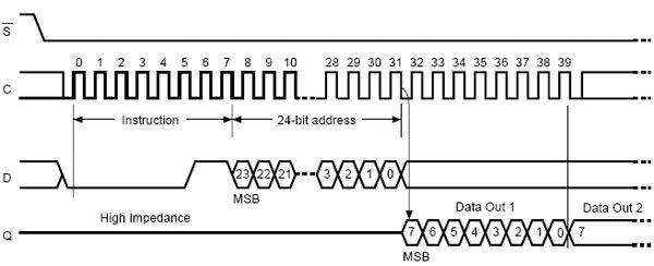
可以分解为两个spi_ transfer一个是写命令,另一个是读数据。具体实现参见ads7846.c中的ads7846_read_state函数。下面内容为此函数。
static void ads7846_read_state(struct ads7846 *ts){
struct ads7846_packet *packet = ts->packet;
struct spi_message *m;
int msg_idx = 0;
int val;
int action;
int error;
while (msg_idx < ts->msg_count) {
ts->wait_for_sync();
m = &ts->msg[msg_idx];
error = spi_sync(ts->spi, m); //调用spi_master发送spi_message ,spi_sync为同步方式发送,还可以用spi_async异步方式,那样的话,需要设置回调完成函数。
if (error) {
dev_err(&ts->spi->dev, "spi_async --> %d\n", error);
packet->tc.ignore = true;
return;
}
/*
* Last message is power down request, no need to convert
* or filter the value.
*/
if (msg_idx < ts->msg_count - 1) {
val = ads7846_get_value(ts, m);
action = ts->filter(ts->filter_data, msg_idx, &val);
switch (action) {
case ADS7846_FILTER_REPEAT:
continue;
case ADS7846_FILTER_IGNORE:
packet->tc.ignore = true;
msg_idx = ts->msg_count - 1;
continue;
case ADS7846_FILTER_OK:
ads7846_update_value(m, val);
packet->tc.ignore = false;
msg_idx++;
break;
default:
BUG();
}
} else {
msg_idx++;
}
}
}
另外也可以选择一些封装好的更容易使用的函数,这些函数可以在include/linux/spi/spi.h文件中找到,如:
extern int spi_write_then_read(struct spi_device *spi,const u8 *txbuf, unsigned n_tx,u8 *rxbuf, unsigned n_rx);