修改S3C2440的时钟工作频率
文章目录
- 修改S3C2440的时钟工作频率
- 时钟概览
- S3C2440A的时钟框图
- 时钟控制逻辑
- FCLK HCLK PCLK的频率比
- 设置MPLL的输出频率
- 写代码
修改S3C2440的时钟工作频率
之前写程序都没有设置过S3C2440的时钟,一上来就是设置寄存器和点灯,这和stm32的使用很不一样。在本文中将设置S3C2440的时钟频率,并用流水灯来看效果。设置的频率如下表。
| 时钟 | 频率 |
|---|---|
| FCLK | 400MHz |
| HCLK | 100MHz |
| PCLK | 50MHz |
时钟概览
打开S3C2440用户手册,查看第七章CLOCK & POWER MANAGEMENT。首先来看概览OVERVIEW的第二段:
The Clock control logic in S3C2440A can generate the required clock signals including FCLK for CPU, HCLK for the AHB bus peripherals, and PCLK for the APB bus peripherals. The S3C2440A has two Phase Locked Loops (PLLs): one for FCLK, CLK, and PCLK, and the other dedicated for USB block (48Mhz). The clock control logic can make slow clocks without PLL and connect/disconnect the clock to each peripheral lock by software, which will reduce the power consumption.
于是可以得到时钟用途表:
| 时钟 | 用途 |
|---|---|
| FCLK | CPU |
| HCLK | AHB |
| PCLK | APB |
S3C2440A拥有两个锁相环(PLL),MPLL用于产生上述三个时钟,UPLL用于产生USB时钟。PLL的原理不清楚,会用就行了。
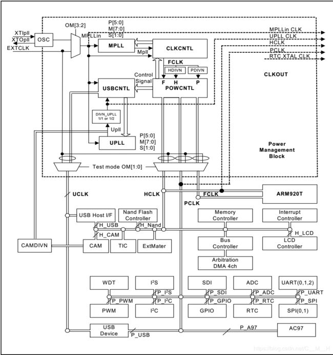
S3C2440A的时钟框图

从左上角看起。时钟源有两个选择:OSC(晶振)和EXTCLK(外部时钟源)。通过OM[3:2]来选择。开始以为OM[3:2]是寄存器OM的两个位,但是在S3C2440手册中,寄存器一般以CON结尾。再翻看一下手册,发现上面有一段话,以及一个表格。

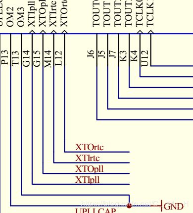
也就是说OM[3:2]其实是S3C2440A上的两个引脚。然后看到JZ2440原理图上对引脚的设置是这样的:

可以看到OM3与OM2引脚都接地,因此OM[3:2]=00B。因此看表格的第一行,选择的是晶振模式,即使用OSC作为时钟源,而OSC又来自XTlpll。然后来看看这个时钟源的频率是多少,在原理图上搜索XTIpll。

可以看到,晶振频率为12MHz。
继续看框图。经过OM[3:2]选择后,MPLL得到一个时钟频率,并且经过处理后输出一个时钟(FCLK),最后经过某个寄存器的配置,得到HCLK和PCLK。然后就可以为CPU、AHB和APB的工作提供时钟了。
现在可以清楚时钟的分配路线是
其中,CLKCNTL是CLOCK CONTROL LOGIC,将在后面介绍。
时钟控制逻辑
先来看两段原文描述。
The Clock Control Logic determines the clock source to be used, i.e., the PLL clock (Mpll) or the direct external clock (XTIpll or EXTCLK). When PLL is configured to a new frequency value, the clock control logic disables the FCLK until the PLL output is stabilized using the PLL locking time. The clock control logic is also activated at power-on reset and wakeup from power-down mode.
时钟控制逻辑描述了时钟源(PLL或外部时钟源)如何被使用。配置PLL为新的值时,FCLK将会被使能,直到PLL输出稳定。FCLK使能也即是CPU不工作了,因为FCLK是提供给CPU的,失能的时间长度由PLL锁定时间来决定。上电复位以及从掉电模式唤醒都会激活时钟控制逻辑。
Figure 7-4 shows the clock behavior during the power-on reset sequence. The crystal oscillator begins oscillation within several milliseconds. When nRESET is released after the stabilization of OSC (XTIpll) clock, the PLL starts to operate according to the default PLL configuration. However, PLL is commonly known to be unstable after power-on reset, so Fin is fed directly to FCLK instead of the Mpll (PLL output) before the software newly configures the PLLCON. Even if the user does not want to change the default value of PLLCON register after reset, the user should write the same value into PLLCON register by software. The PLL restarts the lockup sequence toward the new frequency only after the software configures the PLL with a new frequency. FCLK can be configured as PLL output (Mpll) immediately after lock time.
第二段话引起我注意的是加粗那里,如果上电复位后不编程设定PLLCON,则FCLK直接使用Fin,Fin也就是晶振12MHz。然后来看表。

上电后,CPU并不是马上进入工作。
①电源稳定,此时复位引脚还是低,由nRESET前面的n知道是低电平有效,因此芯片被复位。另外,从OSC的波形来看,此时晶振的震动还不稳定,因此复位引脚延迟拉高是有道理的。
②复位引脚被拉高,此时CPU开始工作了。在JZ2440中复位引脚的拉高是由IMP811T芯片完成的。
③接下来CPU配置PLL的LOCKTIME。所谓LOCKTIME就是PLL此时在工作,CPU的工作停止,要持续LOCKTIME这么久时间,至于单位是什么我也不知道。一般LOCKTIME设置为最大即0XFFFFFFFF。
④此时LOCKTIME结束,可以看到最下面的文字说FCLK已经是新的频率了。
FCLK HCLK PCLK的频率比
继续往下翻手册,又看到一个表格。

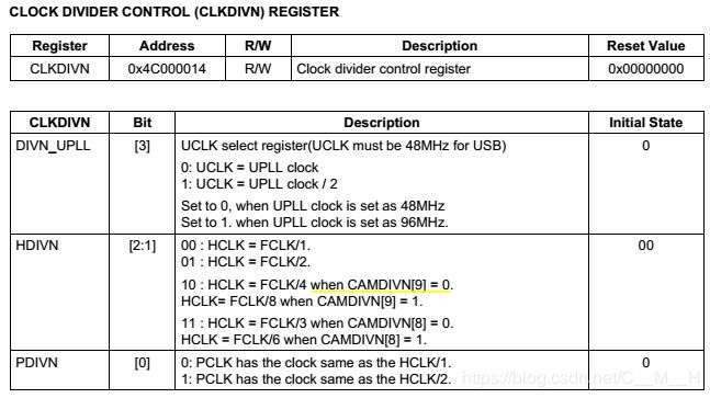
可以看到,这里又重申了时钟的用途。设置CLKDIVN的HDIVN、PDIVN能够决定FCLK HCLK PCLK的频率比。由于后面回设置PLL的输出频率为400MHz,因此特别关注倒数第三行。
CLKDIVN如下:

因此HDIVN[2:1]=10B PDIVN[0]=1,CAMDIVN[9]默认值为0不需理会。
最后,往CLKDIVN写入0X5即可。
紧接着,有一个NOTE,说明如下:
- CLKDIVN should be set carefully not to exceed the limit of HCLK and PCLK.
- If HDIVN is not 0, the CPU bus mode has to be changed from the fast bus mode to the asynchronous bus mode using following instructions(S3C2440 does not support synchronous bus mode).
 MMU_SetAsyncBusMode
 mrc p15,0,r0,c1,c0,0
 orr r0,r0,#R1_nF:OR:R1_iA
 mcr p15,0,r0,c1,c0,0
If HDIVN is not 0 and the CPU bus mode is the fast bus mode, the CPU will operate by the HCLK.This feature can be used to change the CPU frequency as a half or more without affecting the HCLK
and PCLK.
大概意思就是说当HCLK不为0时要加上三行汇编代码,使CPU进入进入异步模式。其中R1_nF:OR:R1_iA=0XC0000000。(这是协处理器指令,为什么是这样需要以后慢慢学习)。
设置MPLL的输出频率
本文的PLL是提供CPU时钟的,因此为Main PLL,即MPLL。上文已经提到了时钟源的选择、时钟控制逻辑和分频的配置。看一下时钟框图,发现还有MPLL的P[5:0] M[7:0] S[1:0]没有设置。原来是前面没有注意到。在时钟框图稍微往下面一点,有这段对PLL的描述:

大概意思是说MPLL的输出要设置M P S三个分频器的值,然后根据公式计算就能得到MPLL的输出。Fin是输入频率。顺便贴一下PLL的框图。

这里也没说P M S在哪个寄存器里,不过可以猜测是和MPLL有关的寄存器。
然后往下看,直到寄存器这一节。

猜测没错,是在MPLLCON里面控制。一般有这种复杂计算公式的,手册都会给出一些值的参考表(串口那一章的波特率设置就是这样)。然后就看到了下面这张表。

可以看到,输入是12MHz,要得到400MHz的FCLK,则MDIV=0X5C PDIV=1 SDIV=1
可设置
MPLLCON=((0x5c<<12)|(1<<4)|(1<<0))
就使得FCLK为400MHz。
写代码
所有源的文件如下:
| start.S | led.c | Makefile | s3c2440_soc.h |
|---|
主要编写的是start.S,led.c为跑马灯程序,s3c2440_soc.h定义的寄存器的地址。
start.S按顺序实现一下功能:
- 关闭看门狗
- 设置LOCKTIME
- 设置分频,FCLK:HCLK:PCLK=400MHz:100MHz:50MHz
- 设置CPU工作于异步模式
- 设置MPLLCON,用于配置MSP分频器的值,得到PLL的输出时钟
- 设置栈,自动判断是nand启动还是nor启动
- 跳转到main函数执行流水灯程序
- 惯例在最后会加上halt标签
特别注意第3步设置分频比不能写在第5步后面,否则nor模式下led不亮,原因不明。
下面为start.S的全部代码
.text
.global _start
_start:
	//close the watchdog
	//WTCON(0X53000000)
	ldr r0,=0x53000000
	ldr r1,=0
	str r1,[r0]

	//set LOCKTIME(0x4c000000) to 0xffffffff
	ldr r0,=0x4c000000
	ldr r1,=0xffffffff
	str r1,[r0]

	//set frequency divider, to make FCLK:HCLK:PCLK=400M:100M;50M
	//CLKDIVN(0X4C000014), HDIVN=10B, PDIVN=1B
	ldr r0,=0x4c000014
	ldr r1,=0x5
	str r1,[r0]

	//now HCLK!=0, we need to set cpu to run in asynchronous mode
	//the following code copy from S3C2440A manual page 7-9
	mrc p15,0,r0,c1,c0,0
	orr r0,r0,#0xc0000000 //R1_nF:OR:R1_iA
	mcr p15,0,r0,c1,c0,0

	//set MPLLCON(0x4c000004), then FCLK = 400MHz
	//input frequency is 12MHz, so MDIV=0X5C, PDIV=1, SDIV=1
	ldr r0,=0x4c000004
	ldr r1,=(0x5c<<12)|(1<<4)|(1<<0)
	str r1,[r0]

	//config mem sp address
	//the following code can judge the board started up with nand or nor
	//try to modify the data in address 0, I write 0 to this address
	//before writting, store [0]'s data to r0
	//after writting, read [0]'s data to r2, compare r2 and r1
	//if equal, the board is working with nand, else with nor
	mov r1,#0
	ldr r0,[r1]
	str r1,[r1]
	ldr r2,[r1]
	cmp r1,r2
	ldr sp,=0x40000000+4096
	moveq sp,#4096
	streq r0,[r1]

	//goto main
	bl main

halt:
	b halt
下面为led.c
#include "s3c2440_soc.h"
void delay(volatile int d){
	while (d--);
}

int main(void){
	int val = 0;  /* val: 0b000, 0b111 */
	int tmp;

	/* 设置GPFCON让GPF4/5/6配置为输出引脚 */
	GPFCON &= ~((3<<8) | (3<<10) | (3<<12));
	GPFCON |=  ((1<<8) | (1<<10) | (1<<12));

	/* 循环点亮 */
	while (1){
		tmp = ~val;
		tmp &= 7;
		GPFDAT &= ~(7<<4);
		GPFDAT |= (tmp<<4);
		delay(100000);
		val++;
		if (val == 8)
			val =0;
	}
	return 0;
}
下面为Makefile
all:
	arm-linux-gcc -c -o start.o start.S
	arm-linux-gcc -c -o led.o led.c
	arm-linux-ld -Ttext 0 start.o led.o -o led.elf
	arm-linux-objcopy -O binary -S led.elf led.bin
	arm-linux-objdump -D led.elf > led.dis

clean:
	rm *.o *.elf *.bin *.dis