相机标定+鸟瞰图生成(VS2017+OpenCV)
一、要求:
1.用自己的手机采集棋盘板定标数据;
2.实现或调用 角点检测、局部特征提取、局部特征匹配算法,标定自己手机的内参;
3.改变外参,生成不同视角的新图像。
二、实验过程:
1.实验前准备:
- 棋盘准备。
- 拍摄图片。用自己的手机多角度拍摄已经准备好的棋盘,共12张图片。放入pic文件夹,按序号命名:testxx.jpg。
- 测量数据。
A.标定板上每个棋盘格的大小:30mmx30mm
B.棋盘角点的行数和列数:9x6
- 安装好OpenCV,在VS2017中建立一个新的VC++空项目。
2.实验原理(查资料得):
(1)角点检测:
- 角点就是极值点,即在某方面属性特别突出的点。角点可以是两条线的交叉处,也可以是位于相邻的两个主要方向不同的事物上的点。
- 角点是图像很重要的特征,对图像图形的理解和分析有很重要的作用。角点在保留图像图形重要特征的同时,可以有效地减少信息的数据量,有利于图像的可靠匹配。
- 目前的角点检测算法可归纳为3类:基于灰度图像的角点检测、基于二值图像的角点检测、基于轮廓曲线的角点检测。
- 本次实验中使用的是OpenCV提供的专用于棋盘相机标定的提取棋盘角点的API。但是角点检测函数返回的值是像素整数坐标,为了使得到的角点坐标更精确,还用到了基于灰度图像的亚像素化角点的API,可以得到浮点型坐标。
(2)相机标定:
- 为确定空间物体表面某点的三维几何位置与其在图像中对应点之间的相互关系,必须建立相机成像的几何模型,这些几何模型参数就是相机参数。在大多数条件下这些参数必须通过实验与计算才能得到,这个求解参数的过程就称之为相机标定(或摄像机标定)。
- 传统相机标定法需要使用尺寸已知的标定物,通过建立标定物上坐标已知的点与其图像点之间的对应,利用一定的算法获得相机模型的内外参数。平面型标定物比三维标定物制作简单,精度易保证,但标定时必须采用两幅或两幅以上的图像。本次实验选择棋盘,并采集2张以上图像。
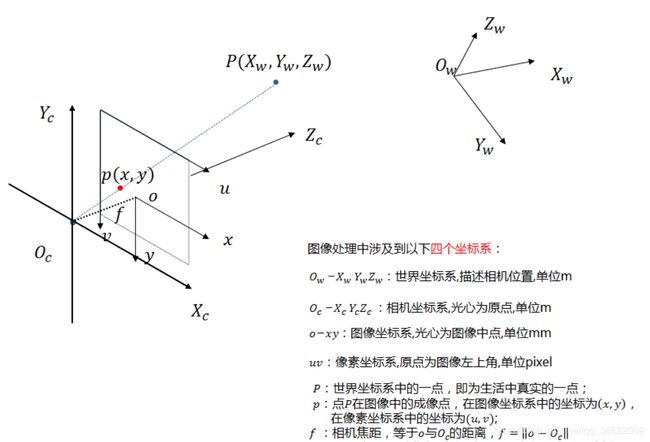
- 空间物体表面某点的三维几何位置与其在图像中对应点之间的关系:关于坐标系转换更详细的解释
(3)透镜畸变:
透镜由于制造精度以及组装工艺的偏差会引入畸变,导致原始图像的失真。镜头的畸变分为径向畸变和切向畸变两类。
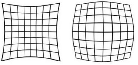
径向畸变就是沿着透镜半径方向分布的畸变,产生原因是光线在原理透镜中心的地方比靠近中心的地方更加弯曲。 成像仪光轴中心的畸变为0,沿着镜头半径方向向边缘移动,畸变越来越严重。畸变的数学模型可以用主点(principle point)周围的泰勒级数展开式的前几项进行描述,通常使用前两项,即k1和k2,对于畸变很大的镜头,可以增加使用第三项k3。
切向畸变是由于透镜本身与相机传感器平面(成像平面)或图像平面不平行而产生的,这种情况多是由于透镜被粘贴到镜头模组上的安装偏差导致。畸变模型可以用两个额外的参数p1和p2来描述:
(4)透视变换:
透视变换矩阵变换公式为:
![]()
这是一个从二维空间变换到三维空间的转换,因为图像在二维平面,故除以Z, (X';Y';Z')表示图像上的点:
![]()
令a33=1, 展开上面公式,得到一个点的情况:4个点可以得到8个方程,即可解出透视变换矩阵A。
(5)鸟瞰图生成原理:
- 摄像机斜视拍摄一物体后,形成的图像会发生变形,如果将图像映射到拍摄物体平面上,相当于将相机垂直于拍摄平面,这样就会得到图像的真实形状。由于这种映射相当于将原图重新透视到另一个平面,这种称之为“重投影”。
- 鸟瞰图的本质就是将图像平面中的信息“重投影”到地平面上,所以,首先要获取两个平面间的投影变换关系H。在程序中,是通过在地平面上放置标定板图像,然后获得地平面上棋盘格图像上四个顶点的坐标(0,0),(widht-1,0),(0,height -1),(wdith-1,height-1);同时,在拍摄的图像平面提取角点,并获得与地平面上四个点对应的角点在图像空间中的坐标值,通过四个坐标点间的对应关系,基于getPerspectiveTransform()函数,获得地平面到图像平面间的投影变换关系H;最后,通过warpPerspective()函数对图像进行逆向映射到地平面空间中。
3.代码实现:点这里下载demo
(1)读取图片
| Mat imageInput = imread (addInexToName (image_index, "pic", ".jpg")); |
(2)准备相机标定参数
(1)图像的亚像素角点
A.提取角点
| Size board_size = Size (9, 6); //棋盘标定板上每行、列的角点数 vector<Point2f> image_corners; // 每幅图像上检测到的角点数组 vector<vector<Point2f>> all_corners; //所有图像角点数组 //提取角点 if (findChessboardCorners (imageInput, board_size, image_corners)==false) { cout << "can not find chessboard corners in "<< addInexToName (image_index, "pic", ".jpg") <<"!\n"; //找不到角点 exit (1); } |
API解析: bool findChessboardCorners( InputArray image, Size patternSize, OutputArray corners, int flags = CALIB_CB_ADAPTIVE_THRESH + CALIB_CB_NORMALIZE_IMAGE );
B.亚像素精确化
| Mat view_gray; cvtColor (imageInput, view_gray, CV_RGB2GRAY); //亚像素精确化 find4QuadCornerSubpix (view_gray, image_corners, board_size); all_corners.push_back (image_corners); |
API解析: bool find4QuadCornerSubpix(InputArray img, InputOutputArray corners, Size region_size );
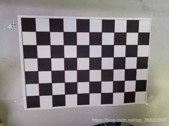
C.在图像上绘制角点,并显示图片,保存图片到新文件夹picOut。
| //在图像上显示角点位置 drawChessboardCorners (imageInput, board_size, image_corners, false); imshow ("Camera Calibration", imageInput); imwrite (addInexToName (image_index, "pic", "_a.jpg"), imageInput); cvWaitKey (500);//不加这句,imshow会显示灰屏 |
(2)标定板上角点的世界坐标
| vector<vector<Point3f>> object_points;// 标定板上角点的三维坐标数组 Size cell_size = Size (30.0, 30.0);//棋盘格的大小 //初始化标定板上角点的三维坐标 int i, j, t; for (t = 0; t { vector<Point3f> position; for (i = 0; i { for (j = 0; j { Point3f realPoint;//假设标定板放在世界坐标系中z=0的平面上 realPoint.x = (float)i*cell_size.width;//第一个点为原点 realPoint.y = (float)j*cell_size.height; realPoint.z = (float)0; position.push_back (realPoint); } } object_points.push_back (position); } |
(3)摄像机内参矩阵
| Mat cameraMatrix = Mat (3, 3, CV_32FC1, Scalar::all (0)); //摄像机内参数矩阵 |
(4)畸变系数
| Mat distCoeffs = Mat (1, 5, CV_32FC1, Scalar::all (0)); //摄像机的5个畸变系数:k1,k2,p1,p2,k3 |
(5)摄像机外参矩阵:图像的旋转向量、平移向量
| vector<Mat> tvecsMat; //图像的旋转向量数组 vector<Mat> rvecsMat;//图像的平移向量数组 |
(2)相机标定
| calibrateCamera (object_points, image_points_seq, image_size, cameraMatrix, distCoeffs, rvecsMat, tvecsMat, 0); |
API解析:double calibrateCamera( InputArrayOfArrays objectPoints, InputArrayOfArrays imagePoints, Size imageSize,InputOutputArray cameraMatrix, InputOutputArray distCoeffs, OutputArrayOfArrays rvecs, OutputArrayOfArrays tvecs, int flags = 0, TermCriteria criteria = TermCriteria(TermCriteria::COUNT + TermCriteria::EPS, 30, DBL_EPSILON) );
(3)输出并保存标定结果
| ofstream fout ("caliberation_result.txt"); // 保存标定结果的文件 Mat rotation_matrix = Mat (3, 3, CV_32FC1, Scalar::all (0)); //保存每幅图像的旋转矩阵 fout << "相机内参数矩阵:" << endl << cameraMatrix << endl << endl; fout << "畸变系数:\n" << distCoeffs << endl << endl << endl; …… |
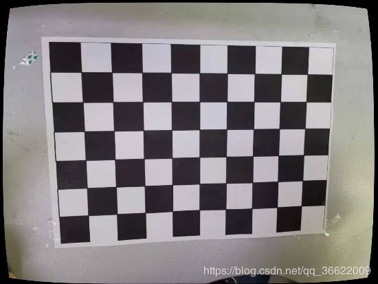
(4)根据标定结果矫正图像
| Mat mapx = Mat (image_size, CV_32FC1); Mat mapy = Mat (image_size, CV_32FC1); Mat R = Mat::eye (3, 3, CV_32F); for (int i = 0; i != image_index; i++) { initUndistortRectifyMap (cameraMatrix, distCoeffs, R, cameraMatrix, image_size, CV_32FC1, mapx, mapy); Mat imageInput = imread (addInexToName (i, "pic", ".jpg")); Mat imageCorrect = imageInput.clone (); remap (imageInput, imageCorrect, mapx, mapy, INTER_LINEAR); imwrite (addInexToName (i, "pic", "_b.jpg"), imageCorrect); } |
API解析:void initUndistortRectifyMap( InputArray cameraMatrix, InputArray distCoeffs, InputArray R, InputArray newCameraMatrix, Size size, int m1type, OutputArray map1, OutputArray map2 );
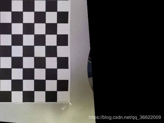
(5)利用透视变换生成鸟瞰图
| int board_w = board_size.width; int board_h = board_size.height; for (int i = 0; i != image_index; i++) { //找到单应矩阵 Mat h = Mat (3, 3, CV_32F, Scalar::all (0)); //选定的4对顶点 vector<Point2f> objPts (4); vector<Point2f> imgPts (4); //每对顶点在顶点数组中的index int indexArray[4] = { 0,//左上角(0,0) //0号 board_w - 1,//右上角(w-1,0)//8号 (board_h - 1)*board_w,//左下角(0,h-1) //5x9=45号 (board_h - 1)*board_w + board_w - 1//右上角(w-1,h-1) //5*9+8=53号 }; //给选定的4对顶点赋值:必须是point2f类型,所以objPts只取x,y坐标 for (int j = 0; j < 4; j++) { objPts[j].x = object_points[i][indexArray[j]].x; objPts[j].y = object_points[i][indexArray[j]].y; imgPts[j] = all_corners[i][indexArray[j]]; } h = getPerspectiveTransform (objPts, imgPts); Mat imageInput = imread (addInexToName (i, "pic", ".jpg")); Mat birdImage = imageInput.clone (); //使用单应矩阵来remap view warpPerspective (imageInput, birdImage, h, image_size, CV_INTER_LINEAR + CV_WARP_INVERSE_MAP + CV_WARP_FILL_OUTLIERS); imwrite (addInexToName (i, "pic", "_c.jpg"), birdImage); } |
API解析:void warpPerspective( InputArray src, OutputArray dst, InputArray M, Size dsize, int flags = INTER_LINEAR, int borderMode = BORDER_CONSTANT, const Scalar& borderValue = Scalar());
三、实验结果:
1.相机标定结果:
(1).手机相机内参数矩阵:
[ 1131.919218712814, 0, 718.6172385878981;
0, 1129.780874113626, 535.3320071414097;
0, 0, 1 ]
(2)畸变系数:
[ 0.127763220456286, -0.5685777233075194, -0.005590515977297709, 0.001382877514914913, 0.9134153599355778]
(3)外参矩阵:以第一幅图像为例:
[0.6591746377197488, 0.7502853398397391, 0.05060341696570259, -2.225831859624084;
-0.6968724853987804, 0.63476347331059, -0.3338324011308702, -2.202196499569492;
-0.2825907572465245, 0.1847897231239953, 0.9412731920896253, -0.2584972913496665
0, 0, 0, 1 ]
2.生成图像:
| Figure 1 原图 |
| Figure 2 标出角点的图像 |
| Figure 3 矫正畸变后的图像 |
| Figure 4 透视变换后的图像 |
