Verilog 按键消抖的一些分析和想法
最近在网上看了下 Verilog 按键消抖方面的设计,有一些个人的想法,做一些分析和记录;
电路板上,通常会提供若干按键,每个按键下赋予了不同的含义,按键的含义由具体的场景来定义;
打个比方,一组电路板上的按键定义如下所示:

在这个例子中,可以看到,硬件原理图中提供了 5 个信号:
KEY_UP
KEY_DOWN
KEY_LEFT
KEY_RIGHT
KEY_ENTER
当 S2~S6 没有被按下的时候,I/O 管脚被通过上拉电阻到 Vcc,即逻辑 1;
当 S2~S6 被按下的时候,这些 I/O 信号直接到 GND,即逻辑 0;
即,按下按键,读 I/O 状态为 0;否则为 1;
当然,这是理想情况,但是现实却很骨感,我们把这个简单的按键操作无限放大后,事实的真相是:按键的时候,可能会存在抖动因素,即需要判断是否是真的按下了按键?是否是因为抖动的因素,导致了误报?这就是按键去抖;

其实按键去抖比较常见,一个比较简易的判断抖动的算法是:如果发现按下了,那么间隔一个很短的时间,再去采集该 I/O 的状态,发现还是按下的状态,那么就认为是真的按键,否则认为是抖动;这里,间隔的这个很短的时间,一般情况可以取 20ms;那么在翻译一下,发现 I/O 状态改变后,隔 20ms,再次采样 I/O 状态,如果发现当前的状态与之前的状态一致,那么说明,I/O 状态改变是不争的事实!

对应的,如果在单片机上,发现有按键按下,那么可以起一个 20ms 的 Timer,到期后再次检测按键即可;
那么 FPGA 上,纯硬件逻辑应该如何应对呢?这就是本章需要了解的部分;
这里分析了几种实现方案:
方案一
具体实现上,有一些技巧,参考了一些设计,具体的实现如下所示(这里分了几个部分,每个部分逐步讲述):
1、定义一个 20ms 的计数器,不断的从 0 ~ 20ms 进行计数
2、20 ms 到期后,将 key 数据进行采样并缓存到 key 0,并在下一个时钟周期,将 key 0 同步到内部缓存的 key 1 中;
3、key 0 与 key 1 有一个时钟周期的差别,利用这一点,进行判断,是否 key 值变化了
Part 1
输入部分,有 4 个按键,分别控制 4 个 LED,按下其中一个,对应的 LED 亮,再次按下,LED 灭
输入时钟频率 25MHz,输入有复位;
首先实现的是 20ms 的计数器,这个不多说了,Verilog 逻辑如下:
module keyscan(
    input clk,
    input n_rst,
    input [3:0] key,
    output [3:0] led
    );

    // Input Clock is 25MHz, so in order to get 20ms
    // The Counter should be 500,000 - 1
    reg [19:0] cnt;
always @(posedge clk or negedge n_rst)
    if(!n_rst) cnt <= 20'd0;
    else if (cnt == 20'd499999) cnt <= 20'd0;
    else cnt <= cnt + 1'b1;
Part 2
当计数器到达 20ms 的时候,将按键的 I/O 信息进行采样,存储到内部 key_sample_new[3:0] 寄存器:
    // Sample Key input every 20ms
    reg [3:0] key_sample_new;
always @(posedge clk or negedge n_rst)
    if(!n_rst) key_sample_new <= 4'b0000;
    else if(cnt == 20'd499999) key_sample_new <= key;
Part 3
用时钟,同步新/旧的采样数据,并且通过新旧的按键对比出到底是哪个被按下了:
    // Sync the latest one to old one
    reg [3:0] key_sample_last;
always @(posedge clk or negedge n_rst)
    if(!n_rst) key_sample_last <= 4'b0000;
    else if(cnt == 20'd499999) key_sample_last <= key_sample_new;

    // latch one clock cycle and check which key have been press down
    wire [3:0] key_pressed = key_sample_last[3:0] & (~key_sample_new[3:0]);
我们按照时间顺序来进行流程分析:
1、首先,clk 的 20ms 的计数器到期了,会将当前的 key 的 I/O 状态进行采样到 key_sample_new[3:0],注意,此刻的 key_sample_last[3:0] 还是上一次的值,并没发生变化,因为此刻的数据刚刚打入 key_sample_new[3:0];
2、组合逻辑生效 key_pressed 信号会根据当前 20ms 拿到的最新的 I/O 状态 key_sample_new[3:0] 取反和上一次的 key_sample_last[3:0] 进行与操作,这里多说一下:
wire [3:0] key_pressed = key_sample_last[3:0] & (~key_sample_new[3:0]);
如果对应的 bit 之前为 1 (也就是 last 中为 1),新采样拿到的数据为 0(也就是 new 中为 0),那么 key_pressed 中对应的 bit 被置为 1,否则,其他任何情况,key_pressed 中对应的 bit 都为 0;换句话来说,只有检测到对应的 bit 由 1 -> 0 的过程,那么就说明被按下了,并将其记录到 key_pressed 中;
3、下一个 clk 的上升沿到来的时候,key_sample_new[3:0] 被同步到了 key_sample_last[3:0] 中,也就是说,如果有真实的按下按键的话,这两个内部寄存器的值,只有一个时钟周期是不一样的;利用这个时钟周期,将数据存储到了 key_pressed;数据完成了同步后,key_sample_last[3:0] 中就代表了上一次的采样数据了;
Part 4
既然按下按键的信息被存储到了 key_pressed 中,那么控制 LED 就靠它了:
reg [3:0] temp_led;
always @(posedge clk or negedge n_rst)
    if(!n_rst) temp_led <= 4'b1111;
    else begin
        if ( key_pressed[0] ) temp_led[0] <= ~temp_led[0];
        if ( key_pressed[1] ) temp_led[1] <= ~temp_led[1];
        if ( key_pressed[2] ) temp_led[2] <= ~temp_led[2];
        if ( key_pressed[3] ) temp_led[3] <= ~temp_led[3];
    end

    assign led[0] = temp_led[0];
    assign led[1] = temp_led[1];
    assign led[2] = temp_led[2];
    assign led[3] = temp_led[3];

endmodule
总的来说,这种方案就是将 20ms 前获取到的 key 值(key_sample_last[3:0]) 和 20ms 拿到的新的 key 值(key_sample_new[3:0]) 进行按位来对比,判断是否有被置位的情况;
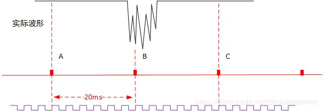
典型的情况是:

当然,还可能存在一些比较极限的情况,就是 20ms 到期的时候,保存最新的 key 值的时候,正好处于抖动期间;
极限的真实按下按键键的情况:
如果此次是真实的按键,而且正好采样时刻 B 位于抖动期间,如果采集到了 0,那么判断条件生效,将会认为有按键按下,如果采集到的是 1,那么相当于认为当前还是未按下的状态,并且会在 C 点判断出已经按键,显然,这种 Case 没有问题;

如果只有抖动,没有按键的情况,如果此次采集到的 key 是 1,那么相安无事,如果采集到的是 0,那么判断就会失效;所以方案一是存在失效风险的;
方案二
针对方案一的缺陷,可以设计成为采样 cnt 一直累加,但是一旦检测到 key 有下降沿的时候,立即重置 cnt 到 0,重新计数;
// Solution 2
    parameter SAMPLE_RATE=6'd10;
// ------------- Key negedge detect Logic Start -------------
    reg [3:0]key_0;
 always @(posedge clk or negedge n_rst)
    if(!n_rst) key_0 <= 4'b1111;
    else key_0 <= key;

    reg [3:0]key_1;
 always @(posedge clk or negedge n_rst)
    if(!n_rst) key_1 <= 4'b1111;
    else key_1 <= key_0;

    // Check key negedge
    wire [3:0]key_neg = key_1[3:0] & (~key_0[3:0]);
// ------------- Key negedge detect Logic End -------------

// ------------- 4 cnt Logic Start -------------
    reg [3:0] cnt_k0;
 always @(posedge clk or negedge n_rst)
    if(!n_rst) cnt_k0 <= 4'd0;
    else if(key_neg[0]) cnt_k0 <= 4'd0;
    else if(cnt_k0 == SAMPLE_RATE) cnt_k0 <= 4'd0;
    else cnt_k0 <= cnt_k0 + 1'b1;

    reg [3:0] cnt_k1;
 always @(posedge clk or negedge n_rst)
    if(!n_rst) cnt_k1 <= 4'd0;
    else if(key_neg[1]) cnt_k1 <= 4'd0;
    else if(cnt_k1 == SAMPLE_RATE) cnt_k1 <= 4'd0;
    else cnt_k1 <= cnt_k1 + 1'b1;

    reg [3:0] cnt_k2;
 always @(posedge clk or negedge n_rst)
    if(!n_rst) cnt_k2 <= 4'd0;
    else if(key_neg[2]) cnt_k2 <= 4'd0;
    else if(cnt_k2 == SAMPLE_RATE) cnt_k2 <= 4'd0;
    else cnt_k2 <= cnt_k2 + 1'b1;

    reg [3:0] cnt_k3;
 always @(posedge clk or negedge n_rst)
    if(!n_rst) cnt_k3 <= 4'd0;
    else if(key_neg[3]) cnt_k3 <= 4'd0;
    else if(cnt_k3 == SAMPLE_RATE) cnt_k3 <= 4'd0;
    else cnt_k3 <= cnt_k3 + 1'b1;
// ------------- 4 cnt Logic End -------------

    // Sample Key input every SAMPLE_RATE
    reg [3:0] key_sample_new;
always @(posedge clk or negedge n_rst)
    if(!n_rst) key_sample_new <= 4'b1111;
    else begin
        if(cnt_k0 == SAMPLE_RATE) key_sample_new[0] <= key[0];
        if(cnt_k1 == SAMPLE_RATE) key_sample_new[1] <= key[1];
        if(cnt_k2 == SAMPLE_RATE) key_sample_new[2] <= key[2];
        if(cnt_k3 == SAMPLE_RATE) key_sample_new[3] <= key[3];
    end

    // Sync the latest one to old one
    reg [3:0] key_sample_last;
always @(posedge clk or negedge n_rst)
    if(!n_rst) key_sample_last <= 4'b1111;
    else key_sample_last <= key_sample_new;

    // latch one clock cycle and check which key have been press down
    wire [3:0] key_pressed = key_sample_last[3:0] & (~key_sample_new[3:0]);

reg [3:0] temp_led;
always @(posedge clk or negedge n_rst)
    if(!n_rst) temp_led <= 4'b0000;
    else begin
        if ( key_pressed[0] ) temp_led[0] <= ~temp_led[0];
        if ( key_pressed[1] ) temp_led[1] <= ~temp_led[1];
        if ( key_pressed[2] ) temp_led[2] <= ~temp_led[2];
        if ( key_pressed[3] ) temp_led[3] <= ~temp_led[3];
    end

    assign led[0] = temp_led[0];
    assign led[1] = temp_led[1];
    assign led[2] = temp_led[2];
    assign led[3] = temp_led[3];
首先使用一个边缘检测电路,检测到 key 的下降沿,一旦发现下降沿,那么 cnt 立马置 0,这样就万无一失了吧?
这种方案的确是比方案一稳一些了,但是在还是有问题:
当 cnt 计数正好计数满的时候,此刻来下降沿了,此刻判断失效!
方案三
针对方案一和方案二的问题,那么是否可以这样设计,计数器开始就别工作了,等到下降沿检测好了,在开始进入工作状态,在计数的过程中如果发现有上升沿,那么重新计数,如果一直计数到满(20ms)为止,那么判定,此次是真的按下了!
上述想法可以使用状态机进行设计,刚刚开始,处于 IDLE 状态,通过边沿检测电路来检测 key 的下降沿;
当检测到 key 下降沿后,进入 SAMPLING 采样状态,一旦发现采样过程有上升沿,那么返回到 IDLE,如果计数器满足后,判定为真实按下,进入 DOWN 状态,并输出相应的输出!
这样就能够解决上面两个方案中遇到的问题啦,Verilog 如下(为了仿真,采样时间定在了 10 个 clk,并且只针对了一个 key):
`timescale 1ns / 1ps
//////////////////////////////////////////////////////////////////////////////////
// Company:
// Engineer:       StephenZhou
//
// Create Date:    10:02:46 11/25/2019
// Design Name:
// Module Name:    keyscan
// Project Name:
// Target Devices: SP6
// Tool versions:
// Description:
//
// Dependencies:
//
// Revision: 0.01
// Revision 0.01 - File Created
// Additional Comments:
//
//////////////////////////////////////////////////////////////////////////////////

module keyscan(
    input clk,
    input n_rst,
    input key,
    output reg led
    );

    // Key posedge and negedge detective logic
    reg key_in_0;
    reg key_in_1;
    always @(posedge clk or negedge n_rst)
    if(!n_rst) begin
        key_in_0 <= 1'b1;
        key_in_1 <= 1'b1;
    end
    else begin
        key_in_0 <= key;
        key_in_1 <= key_in_0;
    end

    wire key_posedge;
    wire key_negedge;

    assign key_posedge = key_in_0 & (~key_in_1);
    assign key_negedge = key_in_1 & (~key_in_0);

    // State Machine
    reg [2:0] state;
    parameter IDLE =     3'b001;
    parameter SAMPLING = 3'b010;
    parameter DOWN =     3'b100;

    reg en_cnt;
    reg led_pressed;

    always @(posedge clk or negedge n_rst)
    if(!n_rst) begin
        state  <= IDLE;
        en_cnt <= 1'b0;
        //led    <= 1'b0;
        led_pressed    <= 1'b0;
    end
    else begin
        case(state)
            IDLE : begin
                if(key_negedge) begin
                    state  <= SAMPLING;
                    en_cnt <= 1'b1;
                    //led    <= 1'b0;
                    led_pressed <= 1'b0;
                end
                else begin
                    state  <= IDLE;
                    en_cnt <= 1'b0;
                    //led    <= 1'b0;
                    led_pressed <= 1'b0;
                end
            end
            SAMPLING : begin
                if(key_posedge) begin
                    state  <= IDLE;
                    en_cnt <= 1'b0;
                    led_pressed <= 1'b0;
                end
                else begin
                    if(cnt_full) begin
                        state  <= DOWN;
                        en_cnt <= 1'b0;
                        led_pressed <= 1'b0;
                    end
                    else begin
                        state  <= SAMPLING;
                        en_cnt <= 1'b1;
                        led_pressed <= 1'b0;
                    end
                end
            end
            DOWN : begin
                state  <= IDLE;
                en_cnt <= 1'b0;
                led_pressed <= 1'b1;
            end
            default : begin
                state  <= IDLE;
                en_cnt <= 1'b0;
                led_pressed <= 1'b0;
            end
       endcase
    end

    // Counter
    reg [3:0] cnt;
    always @(posedge clk or negedge n_rst)
    if(!n_rst) cnt <= 4'b0000;
    else if (en_cnt) cnt <= cnt + 1'b1;
    else cnt <= 4'b0000;

    // Counter Full Logic
    reg cnt_full;
    parameter SAMP_CNT = 4'd10;
    always @(posedge clk or negedge n_rst)
    if(!n_rst) cnt_full <= 1'b0;
    else if(cnt == SAMP_CNT) cnt_full <= 1'b1;
    else cnt_full <= 1'b0;

    // Check posedge of led and keep output
    always @(posedge clk or negedge n_rst)
    if(!n_rst) led <= 1'b0;
    else if(led_pressed) led <= ~led;
    //else led <= 1'b0;

endmodule
代码中均有注释,还是来解释一下:
1、首先使用 key_in_0 和 key_in_1 进行下降沿和上升沿检测电路(Verilog 边沿检测电路)
2、定义状态机,独热码,三个状态 IDLE、SAMPLING、DOWN,检测下降沿状态为 IDLE,一旦有下降沿,则进入 SAMPLING,在此状态下,如果有上升沿,那么认为是抖动,返回 IDLE,继续检测下降沿,同时计数器停止计时
3、在 SAMPLING 状态下计时器到期,那么认为,稳定时间到,则认为有按键按下,并走到 DOWN 状态;
4、DOWN 状态,认为已经检测 OK,那么 led_pressed 赋值为高,led 亮
testbench 为:
`timescale 1ns / 1ps

////////////////////////////////////////////////////////////////////////////////
// Company:
// Engineer:    StephenZhou
//
// Create Date:   13:44:47 11/22/2019
// Design Name:   keyscan
// Module Name:   D:/Xlinx_ISE_Projects/keyscan/tb/key_scan_tb.v
// Project Name:  test
// Target Device:
// Tool versions:
// Description:
//
// Verilog Test Fixture created by ISE for module: keyscan
//
// Dependencies:
//
// Revision:
// Revision 0.01 - File Created
// Additional Comments:
//
////////////////////////////////////////////////////////////////////////////////

module key_scan_tb;

	// Inputs
	reg clk;
	reg n_rst;
	reg key;

	// Outputs
	wire led;

	// Instantiate the Unit Under Test (UUT)
	keyscan uut (
		.clk(clk),
		.n_rst(n_rst),
		.key(key),
		.led(led)
	);

    // Clock Generator freq @20
    always #5 clk = ~clk;

	initial begin
		// Initialize Inputs
		clk = 0;
		n_rst = 0;
		key = 1;

		// Wait 100 ns for global reset to finish
		#100;

		// Add stimulus here
        // Release Reset signal
        n_rst = 1;

        // Wait 100
        #100;

        // Key Input Signal Jitter
        #20 key = 1'b0;
        #15 key = 1'b1;
        #20 key = 1'b0;
        #5  key = 1'b1;
        #15 key = 1'b0;
        #15 key = 1'b1;
        #10 key = 1'b0;
        #5  key = 1'b1;

        #400;
        // Key Input Signal Jitter
        #18 key = 1'b0;
        //#30 key[0] = 1'b0;
        #15 key = 1'b1;
        #20 key = 1'b0;
        #5  key = 1'b1;
        #15 key = 1'b0;
        #15 key = 1'b1;
        #10 key = 1'b0;
        #5  key = 1'b1;


        // Real Push down
        #10 key = 1'b0;
        // Up key
        #200 key = 1'b1;
	end

endmodule
仿真波形全貌为:
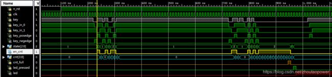
第一个抖动,并没有认为是按键,
放大第一个逻辑为:

第二个是的确按下了,所以逻辑正确,放大第二段逻辑:
