【CCNP路由】OSPF综合实验(一)
@[CCNP-Route]OSPF综合实验(一)
实验目的
- 熟悉 OSPF 的基本配置
- 熟悉 OSPF 网络类型的应用
- 理解不连续区域的网络环境及不连续区域对 OSPF 路由选择的影响
- 掌握 OSPF 不连续区域的几种解决方案
- 掌握 OSPF 区域间和外部路由的汇总
- 掌握 OSPF 默认路由的配置及控制
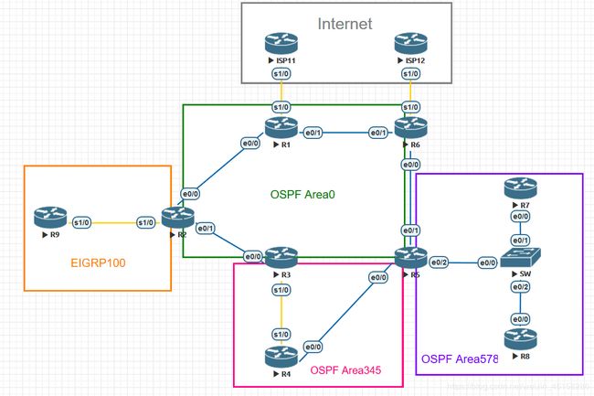
实验拓扑
实验需求及配置过程
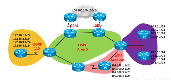
1) 参考拓扑,完成各路由器的基本配置,除图示地址标识外,设备间的地址自己规划,并分别在路由器 R1、R2、R3、R5 和 R6 上各起一个 loopback接口,地址为各路由器的编号,如 R1 的 loopback 地址就为 1.1.1.1,其他以此类推
a.参考实验拓扑,搭建实验环境,如下:
R4:
R4(config)#int lo 11
R4(config-if)#ip add 192.168.1.1 255.255.255.0
R4(config)#int lo 21
R4(config-if)#ip add 192.168.2.1 255.255.255.0
R4(config)#int lo 31
R4(config-if)#ip add 192.168.3.1 255.255.255.0
R4(config)#int lo 41
R4(config-if)#ip add 192.168.4.1 255.255.255.0
R7:
R7(config)#int lo 11
R7(config-if)#ip add 10.7.1.1 255.255.255.0
R7(config)#int lo 21
R7(config-if)#ip add 10.7.2.1 255.255.255.0
R7(config)#int lo 31
R7(config-if)#ip add 10.7.3.1 255.255.255.0
R7(config)#int lo 41
R7(config-if)#ip add 10.7.4.1 255.255.255.0
R8:
R8(config)#int lo 11
R8(config-if)#ip add 10.8.1.1 255.255.255.0
R8(config)#int lo 21
R8(config-if)#ip add 10.8.2.1 255.255.255.0
R8(config)#int lo 31
R8(config-if)#ip add 10.8.3.1 255.255.255.0
R8(config)#int lo 41
R8(config-if)#ip add 10.8.4.1 255.255.255.0
R9:
R9(config)#int lo 11
R9(config-if)#ip add 172.16.1.1 255.255.255.0
R9(config-if)#int lo 21
R9(config-if)#ip add 172.16.2.1 255.255.255.0
R9(config)#int lo 31
R9(config-if)#ip add 172.16.3.1 255.255.255.0
R9(config)#int lo 41
R9(config-if)#ip add 172.16.4.1 255.255.255.0
c.分别在路由器 R1、R2、R3、R5 和 R6 上各起一个 loopback接口,地址为各路由器的编号,如下:
R1:
R1(config)#int lo 1
R1(config-if)#ip add 1.1.1.1 255.255.255.0
R2:
R2(config)#int lo 2
R2(config-if)#ip add 2.2.2.2 255.255.255.0
R3:
R3(config)#int lo 3
R3(config-if)#ip add 3.3.3.3 255.255.255.0
R5:
R5(config)#int lo 5
R5(config-if)#ip add 5.5.5.5 255.255.255.0
R6:
R6(config)#int lo 6
R6(config-if)#ip add 6.6.6.6 255.255.255.0
d.规划设备间的地址,如下:
规划网段:
R1和R2之间的网段为192.168.12.0/24,
R2和R3之间的网段为192.168.23.0/24,
R3和R4之间的网段为192.168.34.0/24,
R4和R5之间的网段为192.168.45.0/24,
R5和R6之间的网段为192.168.56.0/24,
R1和R6之间的网段为192.168.16.0/24,
R2和R9之间的网段为192.168.29.0/24,
R1和ISP11之间的网段为192.168.11.0/24,
R6和ISP12之间的网段为192.168.12.0/24
配置IP地址:
R1:
R1(config-if)#int e0/1
R1(config-if)#ip add 192.168.16.1 255.255.255.0
R1(config-if)#no shutdown
R1(config)#int e0/0
R1(config-if)#ip add 192.168.12.1 255.255.255.0
R1(config-if)#no shutdown
R1(config)#int s1/0
R1(config-if)#ip add 192.168.11.1 255.255.255.0
R1(config-if)#no shutdown
R2:
R2(config-if)#int e0/0
R2(config-if)#ip add 192.168.12.2 255.255.255.0
R2(config-if)#no shutdown
R2(config)#int e0/1
R2(config-if)#ip add 192.168.23.1 255.255.255.0
R2(config-if)#no shutdown
R2(config)#int s1/0
R2(config-if)#ip add 192.168.29.1 255.255.255.0
R2(config-if)#no shutdown
R3:
R3(config)#int e0/0
R3(config-if)#ip add 192.168.23.2 255.255.255.0
R3(config-if)#no shutdown
R3(config)#int s1/0
R3(config-if)#ip add 192.168.34.1 255.255.255.0
R3(config-if)#no shutdown
R4:
R4(config)#int s1/0
R4(config-if)#ip add 192.168.34.2 255.255.255.0
R4(config-if)#no shutdown
R4(config)#int e0/0
R4(config-if)#ip add 192.168.45.1 255.255.255.0
R4(config-if)#no shutdown
R5:
R5(config)#int e0/0
R5(config-if)#ip add 192.168.45.2 255.255.255.0
R5(config-if)#no shutdown
R5(config)#int e0/1
R5(config-if)#ip add 192.168.56.1 255.255.255.0
R5(config-if)#no shutdown
R5(config)#int e0/2
R5(config-if)#ip add 192.168.5.1 255.255.255.0
R5(config-if)#no shutdown
R6:
R6(config)#int e0/0
R6(config-if)#ip add 192.168.56.2 255.255.255.0
R6(config-if)#no shutdown
R6(config)#int e0/1
R6(config-if)#ip add 192.168.16.2 255.255.255.0
R6(config-if)#no shutdown
R6(config)#int s1/0
R6(config-if)#ip add 192.168.12.1 255.255.255.0
R6(config-if)#no shutdown
R7:
R7(config)#int e0/0
R7(config-if)#ip add 192.168.5.2 255.255.255.0
R7(config-if)#no shutdown
R8:
R8(config)#int e0/0
R8(config-if)#ip add 192.168.5.3 255.255.255.0
R8(config-if)#no shutdown
R9:
R9(config)#int s1/0
R9(config-if)#ip add 192.168.29.2 255.255.255.0
R9(config-if)#no shutdown
ISP11:
ISP11(config)#int s1/0
ISP11(config-if)#ip add 192.168.11.2 255.255.255.0
ISP11(config-if)#no shutdown
ISP12:
ISP12(config)#int s1/0
ISP12(config-if)#ip add 192.168.12.2 255.255.255.0
ISP12(config-if)#no shutdown
2)除 ISP 区域外,全网启用 OSPF,并设置各路由器的 RID 为各路由器的编号,根据图示将各网段划分进相应的 OSPF 区域中,要求在 R5 上采用接口级命令将 R5 相应的接口加入到 OSPF 区域中,在其他路由器上采用合适的方式启用 OSPF,并在 R2 上进行 EIGRP 和 OSPF 的双向重分布
a.启用OSPF,具体过程:
a)设置各路由器的编号为RID
b)通告直连网段
i.在其他网段直接用进程级进行通告
ii.在R5上采用接口级进行通告
c)精确通告loopback口的地址
配置过程:
R1:
R1(config)#router ospf 100
R1(config-router)#router-id 1.1.1.1
R1(config-router)#network 192.168.12.0 0.0.0.255 area 0
R1(config-router)#network 192.168.16.0 0.0.0.255 area 0
R2:
R2(config)#router ospf 100
R2(config-router)#router-id 2.2.2.2
R2(config-router)#network 192.168.12.0 0.0.0.255 area 0
R2(config-router)#network 192.168.23.0 0.0.0.255 area 0
R3:
R3(config)#router ospf 100
R3(config-router)#router-id 3.3.3.3
R3(config-router)#network 192.168.23.0 0.0.0.255 area 0
R3(config-router)#network 192.168.34.0 0.0.0.255 area 345
R4:
R4(config)#router ospf 100
R4(config-router)#router-id 4.4.4.4
R4(config-router)#network 192.168.34.0 0.0.0.255 area 345
R4(config-router)#network 192.168.45.0 0.0.0.255 area 345
R4(config-router)#network 192.168.1.1 0.0.0.0 area 345
R4(config-router)#network 192.168.2.1 0.0.0.0 area 345
R4(config-router)#network 192.168.3.1 0.0.0.0 area 345
R4(config-router)#network 192.168.4.1 0.0.0.0 area 345
R5:
R5(config)#router ospf 100
R5(config-router)#router-id 5.5.5.5
R5(config-router)#int e0/0
R5(config-if)#ip ospf 1 area 345
R5(config-if)#int e0/1
R5(config-if)#ip ospf 100 area 0
R5(config-if)#int e0/2
R5(config-if)#ip ospf 100 area 578
R6:
R6(config)#router ospf 100
R6(config-router)#router-id 6.6.6.6
R6(config-router)#network 192.168.56.0 0.0.0.255 area 0
R6(config-router)#network 192.168.16.0 0.0.0.255 area 0
R7:
R7(config)#router ospf 100
R7(config-router)#router-id 7.7.7.7
R7(config-router)#network 192.168.5.0 0.0.0.255 area 578
R7(config-router)#network 10.7.1.1 0.0.0.0 area 578
R7(config-router)#network 10.7.2.1 0.0.0.0 area 578
R7(config-router)#network 10.7.3.1 0.0.0.0 area 578
R7(config-router)#network 10.7.4.1 0.0.0.0 area 578
R8:
R8(config)#router ospf 100
R8(config-router)#router-id 8.8.8.8
R8(config-router)#network 192.168.5.0 0.0.0.255 area 578
R8(config-router)#network 10.8.1.1 0.0.0.0 area 578
R8(config-router)#network 10.8.2.1 0.0.0.0 area 578
R8(config-router)#network 10.8.3.1 0.0.0.0 area 578
R8(config-router)#network 10.8.4.1 0.0.0.0 area 578
b.启用EIGRP,具体过程:
a)进入EIGRP进程,关闭自动汇总
b)通告直连网段
c)对loopback接口进行精确通告
配置过程:
R9:
R9(config)#router eigrp 100
R9(config-router)#no auto-summary
R9(config-router)#network 192.168.29.0
R9(config-router)#network 172.16.1.1 0.0.0.0
R9(config-router)#network 172.16.2.1 0.0.0.0
R9(config-router)#network 172.16.3.1 0.0.0.0
R9(config-router)#network 172.16.4.1 0.0.0.0
R2:
R2(config)#router eigrp 100
R2(config-router)#no auto-summary
R2(config-router)#network 192.168.29.0
此时观察R1的路由表,可以发现还没办法学习到R2和R9的相关路由条目,所以需要在R2上进行EIGRP和OSPF的双向重分布:

c.在R2上进行OSPF和EIGRP的双向重分布,具体过程:
a)在R2上进入OSPF进程
b)把EIGRP重分布进OSPF进程中
c)在R2上进入EIGRP进程
d)把OSPF重分布进EIGRP进程中
配置过程:
R2:
R2(config)#router ospf 100
R2(config-router)#redistribute eigrp 100 subnets
R2(config)#router eigrp 100
R2(config-router)#redistribute ospf 100 metric 1 1 1 1 1
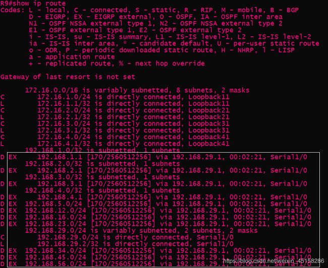
此时再查看R1的路由表,可以观察到学习到了EIGRP的路由条目。

且观察R9的路由表,可以观察到已学习了外部的路由条目:
3)采用合适的命令观察 OSPF 的邻居表、拓扑表和路由表,仔细观察路由表的各路由类型,并测试图示标注 loopback 接口网段间的连通性
a.以R1为例,查看OSPF的三张表
a)查看OSPF邻居表命令:show ip ospf neighbor

b)查看OSPF拓扑表命令:show ip ospf database

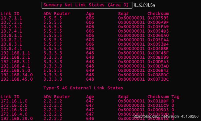
查看拓扑表发现只有四张LSA表,这是因为LSA4为LSA5服务,有4类肯定有5类,而有5类不一定有4类。
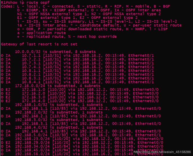
c)查看OSPF路由表命令:show ip route ospf
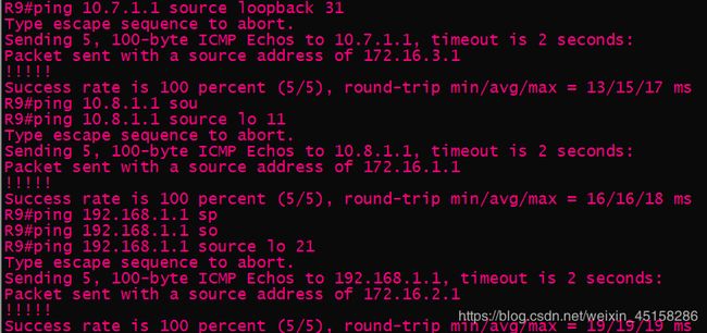
b.测试loopback接口网段间的连通性,如下:
如果无法ping通R7和R8上的loopback接口,确认交换机三个接口是否打开。
4)要求骨干区域能够快速收敛,并让 R5 成为区域 578 中的 DR
a.要使骨干区域(Area 0)能够快速收敛,即把Area 0里接口的网络类型都改成point-to-point,如下:
R1:
R1(config)#int range e0/0-1
R1(config-if-range)#ip ospf network point-to-point
R2:
R2(config)#int range e0/0-1
R2(config-if-range)#ip ospf network point-to-point
R3:
R3(config)#int e0/0
R3(config-if)#ip ospf network point-to-point
R5:
R5(config)#int e0/1
R5(config-if)#ip ospf network point-to-point
R6:
R6(config)#int range e0/0-1
R6(config-if-range)#ip ospf network point-to-point
b.使R5成为Area578中的DR,即进入R5的e0/2接口(在区域578内),更改其优先级(越大越优),如下:
R5:
R5(config)#int e0/2
R5(config-if)#ip ospf priority 10
5)采用合适的方案确保当骨干网络的任意链路中断的时候不会影响骨干网的连通性
首先在R9上用traceroute命令查看到10.7.1.1的路径,如下:

把R1的接口关闭模拟链路中断状态,此时发现不可达:

为保证骨干网的连通性,有两种方案:
a.区域链路(简单)
配置过程:
R3:
R3(config)#router ospf 100
R3(config-router)#area 345 virtual-link 5.5.5.5
R5:
R5(config)#router ospf 100
R5(config-router)#area 345 virtual-link 3.3.3.3
b.隧道(不能在特殊区域进行区域链路时使用)
配置过程:
R3:
R3(config)#int tunnel 1
R3(config-if)#tunnel source 192.168.34.1
R3(config-if)#tunnel destination 192.168.45.2
R3(config-if)#ip add 35.35.35.3 255.255.255.0
R3(config-if)#ip ospf 100 area 0
R5:
R5(config)#int tunnel 1
R5(config-if)#tunnel source 192.168.45.2
R5(config-if)#tunnel destination 192.168.34.1
R5(config-if)#ip add 35.35.35.5 255.255.255.0
R5(config-if)#ip ospf 100 area 0
此时发现traceroute后可以连通,走的是下半部分的链路:

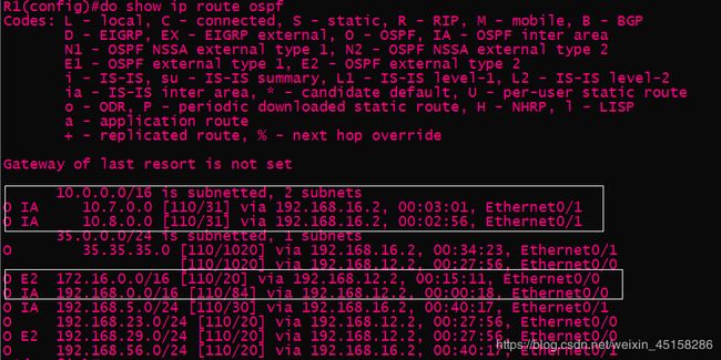
6)观察各路由器上的路由表信息,然后在合适的路由器上进行必要的路由汇总,对比汇总之后各路由器路由表的变化,并观察和测试明细路由与汇总路由之间的关系
a.在R2上汇总R9上4个loopback接口的路由,如下:
R2:
R2(config)#router ospf 100
R2(config-router)#summary-address 172.16.0.0 255.255.0.0
b.在R3和R5汇总R4上4个loop back接口的路由,如下:
R5:
R5(config)#router ospf 100
R5(config-router)#area 345 range 192.168.0.0 255.255.0.0
R3:
R3(config)# router ospf 100
R3(config-router)#area 345 range 192.168.0.0 255.255.0.0
c.在R5上汇总R7和R8上8个loopback接口的路由,如下:
R5:
R5(config)#router ospf 100
R5(config-router)#area 578 range 10.7.0.0 255.255.0.0
R5(config-router)#area 578 range 10.8.0.0 255.255.0.0
汇总后的路由表如下:
7)采用合适的方案,实现图示标注的 loopback 网段可以访问 ISP 上的主机100.100.100.100
使用NAT,具体过程:
a.先配置ISP11和ISP12的loopback接口地址为100.100.100.100/24
ISP11:
ISP11(config)#int lo 1
ISP11(config-if)#ip add 100.100.100.100 255.255.255.0
ISP12:
ISP12(config)#int lo 1
ISP12(config-if)#ip add 100.100.100.100 255.255.255.0
b.在R1和R6上配置允许的网段
R1(R6):
R1(config)#access-list 1 permit 192.168.0.0 0.0.255.255
R1(config)#access-list 1 permit 172.16.0.0 0.0.255.255
R1(config)#access-list 1 permit 10.7.0.0 0.0.255.255
R1(config)#access-list 1 permit 10.8.0.0 0.0.255.255
c.配置NAT
R1(R6):
R1(config)#ip nat inside source list 1 interface s1/0 overload
R1(config)#int range e0/0-1
R1(config-if-range)#ip nat inside
R1(config)#int s1/0
R1(config-if)#ip nat outside
d.配置边界路由指向外网,并下发
R1(R6):
R1(config)#ip route 0.0.0.0 0.0.0.0 s1/0
R1(config)#router ospf 100
R1(config-router)#default-information originate
此时发现可以ping通,如下:


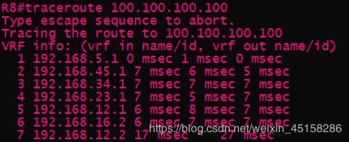
8)要求各链路正常情况下,内网优选 ISP1 的链路对外部网络进行访问,当与 ISP1 的链路出现故障的时候,自动切换到 ISP2 的链路对外部网络进行访问,使用tracert 观察验证该现象。
a.为使内网优先选ISP1的链路对外部网络进行访问,可以选择把R6的开销增大:
R6(config-router)#default-information originate metric 500
b.但有默认路由的存在,可能导致路径仍选择ISP12,此时有两种方法:
① 浮动路由
R6(config)#ip route 0.0.0.0 0.0.0.0 s1/0 150
② 更改OSPF开销
R5(config)#int e0/1
R5(config-if)#ip ospf cost 100
R6(config-router)#default-information originate metric 500
此时关闭R1的s1/0,模拟链路出故障,可以观察到链路都选择走ISP12的路径,如下:
