arduino教程-9. 串行外设接口(spi)
文章目录
- 相关资料
- 1. spi针脚
- Arduino 串行外设接口
- 串行外设接口简介
- 板的SPI引脚
- SPI.h 库
- SPI.h官方示例
- SPI为主机
- 例子
- SPI为从机
- 例子
相关资料
SPI library
SPI原文:http://wiki.dzsc.com/4328.html
《Arduino》SPI模块官方手册:https://www.arduino.cc/en/Tutorial/SPIEEPROM
《Arduino》SPI模块官方手册【翻译】:https://blog.csdn.net/xxxxxx91116/article/details/42620413
1. spi针脚
The following table display on which pins the SPI lines are broken out on the different Arduino boards:
| Arduino / Genuino Board | MOSI | MISO | SCK | SS (slave) | SS (master) | Level |
|---|---|---|---|---|---|---|
| Uno or Duemilanove | 11 or ICSP-4 | 12 or ICSP-1 | 13 or ICSP-3 | 10 | - | 5V |
| Mega1280 or Mega2560 | 51 or ICSP-4 | 50 or ICSP-1 | 52 or ICSP-3 | 53 | - | 5V |
| Leonardo | ICSP-4 | ICSP-1 | ICSP-3 | - | - | 5V |
| Due | ICSP-4 | ICSP-1 | ICSP-3 | - | 4, 10, 52 | 3,3V |
| Zero | ICSP-4 | ICSP-1 | ICSP-3 | - | - | 3,3V |
| 101 | 11 or ICSP-4 | 12 or ICSP-1 | 13 or ICSP-3 | 10 | 10 | 3,3V |
| MKR1000 | 8 | 10 | 9 | - | - | 3,3V |
Note that MISO, MOSI, and SCK are available in a consistent physical location on the ICSP header; this is useful, for example, in designing a shield that works on every board.
![]()
Arduino 串行外设接口
串行外设接口简介
串行外设接口(SPI)是微控制器使用的同步串行数据协议,用于在短距离内快速与一个或多个外围设备通信。它还可以用于两个微控制器之间的通信。
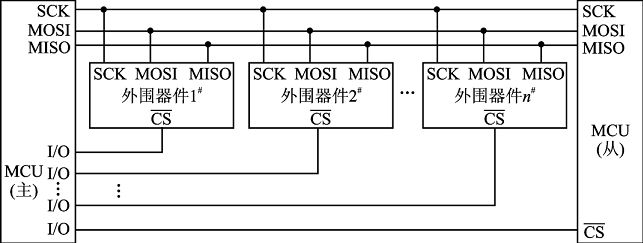
通过SPI连接,总有一个主设备(通常是微控制器)控制外围设备。通常,所有设备共有三条线路,
板的SPI引脚
SPI使用以下四条线:
- SCK - 这是由主机驱动的串行时钟。
- MOSI - 从主机向外设发送的数据线(Master Output, Slave Input)。
- MISO - 从外设向主机发送数据的线(Master Input, Slave Output)。
- SS : 外设选择线(Slave Select),指定要联机的外设,此线输入0,代表选取,1代表未选取。这条线也称为CS(Chip Select,芯片选择线或简称片选)。分配给所有的设备,用于enable/disable指定的设备,同时用于避免由于线路忙导致的错误传输。
Arduino的ATmega系列处理器内建SPI接口,位于数字10~13脚。SPI联机包含一个主机(Master)和一个或多个外设装置,每个SPI外设需要单独连接SS线,

SPI最大的问题在于它的标准太不严格了,这导致各个设备在实现它的时候都有一些不同,这就意味着当我们在编写接口代码的时候必须仔细阅读设备数据参数。通常来说有编号为0-3的3种传输模式(不是4种么?)这些模式控制数据是在时钟信号的高电平还是低电平传入或传出,以及在高或低电平时时钟无效。
所有的SPI设置都由Arduino SPI控制寄存器(SPCR)来决定。这个寄存器就是微控制器内存的一个字节,它是可读写的。寄存器提供的服务通常有3类:控制、数据和状态。
- 控制寄存器(SPCR)
编码设置控制多种微控制器的功能。通常控制寄存器中的一个位影响某个特定的设置,比如速度和极性(这个是啥?) - 数据寄存器(SPDR)
仅仅hold住了一个字节。比如,SPI数据寄存器hold住了要发往MOSI线的一个字节,或者这个数据是要从MISO线传入的。 - 状态寄存器(SPSR)
根据多种微控制器的条件改变其状态。比如,SPI状态寄存器(SPSR)的第七位被设置为1表示有数据从SPI传入或传出。
SPI控制寄存器(SPCR)共有8位,每一个都控制了一种特定的SPI设置。
SPCR
| 7 | 6 | 5 | 4 | 3 | 2 | 1 | 0 |
|---|---|---|---|---|---|---|---|
| SPIE | SPE | DORD | MSTR | CPOL | CPHA | SPR1 | SPR0 |
- SPIE:置为1时,表示enable SPI的中断
- SPE:置为1时,表示enable SPI
- DORD:发送数据时,设置为1表示最低有效位,0表示最高有效位。请各自脑补最低有效位和最高有效位。。。
- MSTR:设置为1表示Arduino为master模式,0为slave模式
- CPOL:设置为1时,数据时钟在高时无效,设置为0时,在低时无效
- CPHA:设置为1时,时钟低电平时是Samples data(样本数据?),0时时钟高电平是Sampledata
- SPR1和SPR0:设置SPI的速度,00是最快的(4MHz),11是最慢的(250KHz)
这些意味着当对一个新的SPI设备编码的时候,我们需要注意一些事情并根据如下设置SPCR:
- 数据传入是最高有效位(MSB)还是最低有效位(LSB)?
- 数据时钟无效是在高还是低?
- samples是在时钟脉冲上升沿还是下降沿?
- SPI 运行的速度是多少?
SPI.h 库
-
SPI.begin() - 通过将SCK,MOSI和SS设置为输出来初始化SPI总线,将SCK和MOSI拉低,将SS拉高。
-
SPI.setClockDivider(分频器) - 相对于系统时钟设置SPI时钟分频器。在基于AVR的板上,可用的分频器为2,4,8,16,32,64或128。默认设置为SPI_CLOCK_DIV4,它将SPI时钟设置为系统时钟的四分之一(对于20 MHz的电路板为5 Mhz)。
Divider - 它可以是(SPI_CLOCK_DIV2,SPI_CLOCK_DIV4,SPI_CLOCK_DIV8, SPI_CLOCK_DIV16,SPI_CLOCK_DIV32,SPI_CLOCK_DIV64,SPI_CLOCK_DIV128)。
-
SPI.transfer(val) - SPI传输基于同时发送和接收:接收的数据在receivedVal中返回。
-
SPI.beginTransaction(SPISettings(speedMaximum,dataOrder,dataMode))
speedMaximum是时钟,
dataOrder(MSBFIRST或LSBFIRST),
dataMode(SPI_MODE0,SPI_MODE1,SPI_MODE2或SPI_MODE3)。
SPI中有四种操作模式,如下所示:
- 模式0(默认值) - 时钟通常为低电平(CPOL = 0),数据在从低电平到高电平(前沿)(CPHA = 0)的转换时采样。
- 模式1 - 时钟通常为低电平(CPOL = 0),数据在从高电平到低电平(后沿)(CPHA = 1)的转换时采样。
- 模式2 - 时钟通常为高电平(CPOL = 1),数据在从高电平到低电平(前沿)(CPHA = 0)的转换时采样。
- 模式3 - 时钟通常为高电平(CPOL = 1),数据在从低电平到高电平(后沿)(CPHA = 1)的转换时采样。
- SPI.attachInterrupt(handler) - 当从设备从主设备接收数据时调用的函数。
SPI.h官方示例
-
http://arduino.cc/en/Tutorial/BarometricPressureSensor
-
http://arduino.cc/en/Tutorial/SPIDigitalPot
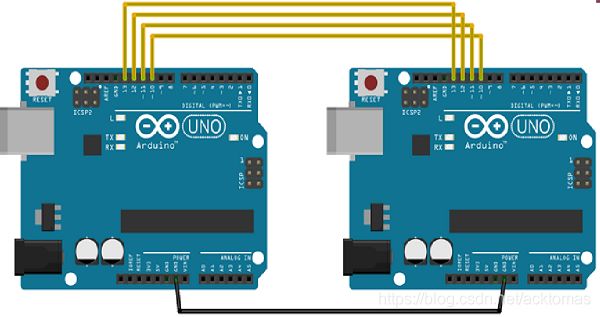
现在,我们将两个Arduino UNO板连接在一起;一个作为主机,另一个作为从机。 -
(SS):引脚10
-
(MOSI):引脚11
-
(MISO):引脚12
-
(SCK):引脚13
接地是常见的。以下是两个电路板之间的连接的图示:
SPI为主机
例子
#include

void setup (void) {
   Serial.begin(115200); //set baud rate to 115200 for usart
   digitalWrite(SS, HIGH); // disable Slave Select
   SPI.begin ();
   SPI.setClockDivider(SPI_CLOCK_DIV8);//divide the clock by 8
}

void loop (void) {
   char c;
   digitalWrite(SS, LOW); // enable Slave Select
   // send test string
   for (const char * p = "Hello, world!\r" ; c = *p; p++) {
      SPI.transfer (c);
      Serial.print(c);
   }
   digitalWrite(SS, HIGH); // disable Slave Select
   delay(2000);
}
SPI为从机
例子
#include Arduino开发板ICSP接口中MOSI, MISO,SCK为SPI接口,有的开发板D11,D12,D13管脚默认和SPI接口连接(如UNO PLUS),有的开发板默认不连接。Accessory Shield开发板中OLED则是通过SPI接口控制。但本章教程作为Arduino的入门教程,OLED的程序较为复杂,在这里不打算讲解OLED的程序。在这里一Arduino IDE自带的例程讲解如何使用Arduino的SPI接口。
点击File->Examples->SPI->DigitalPotControl打开工程。程序如下:
// inslude the SPI library:

#include
// set pin 10 as the slave select for the digital pot:
const int slaveSelectPin = 10;

void setup() {
  // set the slaveSelectPin as an output:
  pinMode (slaveSelectPin, OUTPUT);
  // initialize SPI:
  SPI.begin();
}

void loop() {
  // go through the six channels of the digital pot:
  for (int channel = 0; channel < 6; channel++) {
    // change the resistance on this channel from min to max:
    for (int level = 0; level < 255; level++) {
      digitalPotWrite(channel, level);
      delay(10);
    }
    // wait a second at the top:
    delay(100);
    // change the resistance on this channel from max to min:
    for (int level = 0; level < 255; level++) {
      digitalPotWrite(channel, 255 - level);
      delay(10);
    }
  }
}

void digitalPotWrite(int address, int value) {
	  // take the SS pin low to select the chip:
	  digitalWrite(slaveSelectPin, LOW);
	  //  send in the address and value via SPI:
	  SPI.transfer(address);
	  SPI.transfer(value);
	  // take the SS pin high to de-select the chip:
	  digitalWrite(slaveSelectPin, HIGH);
}
程序分析:
程序开始先引入SPI头文件SPI.h。SPI接口包含MOSI, MISO,SCK,CS四根线。其中MOSI, MISO,SCK已经固定引脚。而CS为片选引脚,可随意选择哪个引脚作为CS.程序中
const int slaveSelectPin = 10; //定义D10作为片选信号。
setup()函数中调用SPI.begin()初始化SPI接口。此处为默认设置。若要设置具体参数可使用如下语句初始化SPI.
SPI.beginTransaction(SPISettings(14000000, MSBFIRST, SPI_MODE0));
SPISettings()函数设置SPI传输模式,SPI.beginTransaction()函数根据SPISettings()初始化SPI.
此处为设置SPI速率为14MHZ,高位先传输,模式0。
digitalWrite(slaveSelectPin, LOW);
传输SPI前先拉低片选管脚,使能SPI设备。
SPI.transfer(val);
SPI传输函数,参数val为要发送的字节,函数返回值为接收到的数据。
digitalWrite(slaveSelectPin, HIGH);
SPI传输结束释放片选管脚。
