五分钟快速过完Verilog HDL基本概念(1)
Verilog既是一种行为描述的语言也是一种结构描述语言。Verilog模型可以是实际电路的不同级别的抽象。这些抽象的级别包括:
-
系统级(system):用高级语言结构实现设计模块的外部性能的模型。
-
算法级(algorithm):用高级语言结构实现设计算法的模型。
-
RTL级(Register Transfer Level):描述数据在寄存器之间流动和如何处理、控制这些数据流动的模型。
以上三种都属于行为描述,只有RTL级才与逻辑电路有明确的对应关系。
-
门级(gate-level):描述逻辑门以及逻辑门之间的连接的模型。
-
开关级(switch-level):描述器件中三极管和储存节点以及它们之间连接的模型。
Verilog HDL行为描述语言具有以下功能:
- 可描述顺序执行或并行执行的程序结构。
- 用延迟表达式或事件表达式来明确地控制过程的启动时间。
- 通过命名的事件来触发其它过程里的激活行为或停止行为。
- 提供了条件如if-else、case、循环程序结构。
- 提供了用于建立表达式的算术运算符、逻辑运算符、位运算符。
- Verilog HDL语言作为一种结构化的语言也非常适合于门级和开关级的模型设计。
1. Verilog HDL模块的模板
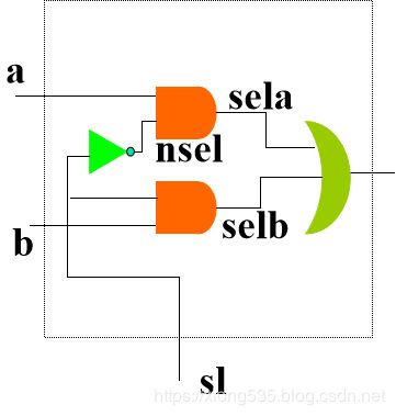
module twomux (out, a, b, sl);
  input a, b, sl;
  output out;
      not u1 (nsel, sl );
      and #1 u2 (sela, a, nsel);
      and #1 u3 (selb, b, sl);
      or  #2 u4 (out, sela, selb);
endmodule
  module muxtwo (out, a, b, sl);
    input a,b,sl;
    output out;
    reg out;
    always @(sl or a or b)
    if (! sl)  out = a;
    else out = b;
  endmodule
MUX(多路选择器)的行为可以描述为:只要信号a或b或sl发生变化,如果sl为0则选择a输出;否则选择b输出。
这个行为的描述并没有说明如果输入 a 或 b是三态的(高阻时)输出应该是什么,但有具体结构的真实电路是有一定的输出的。没有考虑延时问题
    module  adder ( count,sum,a,b,cin );
      input [2:0] a,b;
      input   cin;
      output  count;
      output [2:0] sum;
      assign {count,sum}=a+b+cin;
    endmodule
这个例子描述了一个三位的加法器。从例子中可以看出,整个Verilog HDL程序是位于module和endmodule声明语句之间的
  module   compare ( equal,a,b );
            output  equal;          //声明输出信号equal
            input [1:0] a,b;        //声明输入信号a,b
            assign  equal=(a==b)?1:0;
            /*如果两个输入信号相等则输出为1。否则输出为0*/
  endmodule
这个程序描述了一个比较器.在这个程中,/…/和//…表示注释部分,注释只是为了方便程序员理解程序,对编译是不起作用的。
module trist2(out,in,enable);
	output out;
	input in ,enable;
	bufil1 mybuf(out,in,enable);
endmodule
程序通过调用一个在Verilog语言提供的原语库中现存的三态驱动器元件bufil1来实现其逻辑功能。这个调用过程也称为库元件bufif1的实例化,在本模块中它被具体化为mybuf.
module <顶层模块名> (< 输入输出端口列表>) ;
output 输出端口列表;
input 输入端口列表;
//(1)使用assign语句定义逻辑功能
wire 结果信号名;
assign <结果信号名> = 表达式 ;
//(2)使用always块定义逻辑功能
always @(<敏感信号表达式>)
    begin
       //过程赋值语句
        //if语句
        // case语句
       // while,repeat,for循环语句
       // task,function调用
   end
