卡通渲染描边的另一种做法
在我之前的文章中有一遍的说描边的问题汇总的:
https://blog.csdn.net/llsansun/article/details/83744775
这里面也说了一些问题,最典型的问题是描边的菱角比较突出时,会导致描边出现断层,原因其实也很简单,我们描边都是朝法线方向扩充的,那么菱角的情况就是说明两个边接近90度或超过。那么法线外扩后其实很明显就会出现断层。
那么其实还有其他办法做描边,比如物体轮廓描边可以用卷积,然后用sobal算子做。
还有一个做外轮廓描边的方法是后处理的方法,但是后处理会有比较明显的性能问题,因为一般后处理我们用在onrenderimage上,他是会做全屏的拷贝的,那么相当于会有两个全屏rt在内存中,然后我们一般是在onrenderimage中做比较图片放大等来实现描边。
但今天我想介绍另一种方式的描边,他类似后处理而又不属于后处理。
主要思想是把采样每个像素附近的像素,叠加这些像素来达到描边效果。
步骤是:
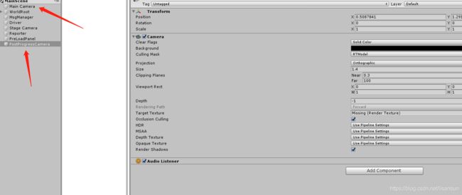
1.在scene里加多一个相机,并且相机和渲染角色的主相机的信息要保持一致。
2.在渲染角色的材质列表中加多一个材质(可以动态添加),这个材质的shader用描边的shader代替。并且maintexture给到角色的贴图信息(因为我是基于已经渲染出的角色的rt来做描边的)
//这里开始多添加一个材质并且设置shader为我们要做描边的shader
private void CreatePostProgressRenderTarget()
        {
            DestroyMats();
            if (mRenderTarget != null)
            {
                Material mat = new Material(Shader.Find("Transparent/Simple Outline"));
                mat.mainTexture = mRTPostProgress;
                mat.SetFloat("_Outline", 0.4f);
                var newMats = new Material[2];
                var mats = mRenderTarget.GetComponent().materials;
                newMats[0] = mats[0];
                newMats[1] = mat;
                mRenderTarget.GetComponent().materials = newMats;
            }
        }
//后处理的rt创建,并且用协程做update。当然大家可以用自己的mono来update
        void PostProgress()
        {
            if (mPostProgressCamera == null)
            {
                mPostProgressCamera = GameObject.Find("PostProgressCamera").GetComponent();
            }
            if (mRTPostProgress == null)
            {
                mRTPostProgress = RenderTexture.GetTemporary(Screen.width, Screen.height, 16, RenderTextureFormat.ARGB32, RenderTextureReadWrite.sRGB, 2);
                mRTPostProgress.wrapMode = TextureWrapMode.Clamp;
                mRTPostProgress.filterMode = FilterMode.Bilinear;
                mRTPostProgress.anisoLevel = 2;
                mPostProgressCamera.targetTexture = mRTPostProgress;
            }
            CreatePostProgressRenderTarget();
            Coroutines.Stop(PostUpdate());
            Coroutines.Run(PostUpdate());
        }
//设置相机的信息一致
        IEnumerator PostUpdate()
        {
            while (true)
            {
                mPostProgressCamera.transform.localPosition = mCamera.transform.localPosition;
                mPostProgressCamera.transform.localRotation = mCamera.transform.localRotation;
                mPostProgressCamera.transform.localScale = mCamera.transform.localScale;
                mPostProgressCamera.orthographic = mCamera.orthographic;
                mPostProgressCamera.fieldOfView = mCamera.fieldOfView;
                yield return null;
            }
        }
当然要记得不需要时要销毁创建的东西。
3.材质已经加上了,剩下最后一步也就是最关键的一步就是outline的shader编写
// Shader targeted for low end devices. Single Pass Forward Rendering.
Shader "Transparent/Simple Outline"
{
    // Keep properties of StandardSpecular shader for upgrade reasons.
    Properties
    {
		_MainTex ("Base (RGB)", 2D) = "white" {}
		_OutlineColor("Outline Color", Color) = (0,0,0,1)
		_Outline("Outline width", Range(0.000, 10)) = 0.015
    }

    SubShader
    {
        Tags { "Queue" = "Transparent-50" "IgnoreProjector"="True" "RenderType"="Transparent" }
        LOD 300

		Cull Off
		Lighting Off
		Fog { Mode Off }

		ZWrite Off
		AlphaTest Off
		Blend SrcAlpha OneMinusSrcAlpha
		Pass
		{

			Name "OUTLINE"

			CGPROGRAM

				#include "UnityCG.cginc"
				#pragma target 3.0
				#pragma multi_compile_fwdbase
				#pragma vertex vert
				#pragma fragment frag

				CBUFFER_START(UnityPerMaterial)

				uniform sampler2D _MainTex;
				uniform half4 _MainTex_ST;
				half _Outline;
				fixed4 _OutlineColor;
				CBUFFER_END

				struct V2F
				{
					float4 pos:SV_POSITION;
					half2 uv : TEXCOORD0;//一级纹理坐标(右上)
					half2 uv20 : TEXCOORD1;
					half2 uv21 : TEXCOORD2;
					half2 uv22 : TEXCOORD3;
					half2 uv23 : TEXCOORD4;
					half2 uv24 : TEXCOORD5;
					half2 uv25 : TEXCOORD6;
					half2 uv26 : TEXCOORD7;
					half2 uv27 : TEXCOORD8;
				};

				V2F vert(appdata_full v)
				{
					V2F o;
					//v.vertex.x *= (1 + _Outline);
					//v.vertex.y *= (1 + 0.5 * _Outline);
					o.pos = UnityObjectToClipPos (v.vertex);
					o.uv = TRANSFORM_TEX(v.texcoord, _MainTex);

					half h = 0.005h;

					o.uv20 = v.texcoord + _MainTex_ST.xy * half2(_Outline * h, _Outline * h);
					o.uv21 = v.texcoord + _MainTex_ST.xy * half2(-_Outline * h, -_Outline * h);
					o.uv22 = v.texcoord + _MainTex_ST.xy * half2(_Outline * h, -_Outline * h);
					o.uv23 = v.texcoord + _MainTex_ST.xy * half2(-_Outline * h, _Outline * h);
					o.uv24 = v.texcoord + _MainTex_ST.xy * half2(_Outline, 1);
					o.uv25 = v.texcoord + _MainTex_ST.xy * half2(-_Outline, 1);
					o.uv26 = v.texcoord + _MainTex_ST.xy * half2(1, -_Outline);
					o.uv27 = v.texcoord + _MainTex_ST.xy * half2(1, _Outline);
					return o;
				}

				fixed4 frag(V2F i) :COLOR
				{
					half4 texcol = tex2D( _MainTex, i.uv );
					texcol += tex2D(_MainTex, i.uv20);
					texcol += tex2D(_MainTex, i.uv21);
					texcol += tex2D(_MainTex, i.uv22);
					texcol += tex2D(_MainTex, i.uv23);
					texcol += tex2D(_MainTex, i.uv24);
					texcol += tex2D(_MainTex, i.uv25);
					texcol += tex2D(_MainTex, i.uv26);
					texcol += tex2D(_MainTex, i.uv27);
					texcol.rgb = _OutlineColor.rgb;
					return texcol;
				}
			ENDCG
		}

    }
Fallback Off
}
主要思路是采样附近8个方向的文理,然后叠加起来,达到我们想要的效果。
这种方式效果是很明显的,没有断层的问题
性能分析:
1.首先drawcall上会增加一个,但我想说无论你用法线扩充也会多一个pass。后处理也是。
2.我们有9次采样,gpu的运算肯定会大点(肯定比法线扩充会大多),但真机跑起来并不会有严重的掉帧,并且比法线扩充好多了。
3.内存上增加了一个材质,基本可以忽略。
所以综合来看这个方式还是不错的可以达到设计想要的效果。


