03 UGW6.1.1 uboot分析
/*****************************************************************************************************************
Document Author : ELvins Fu
Digtal technology park, A3 -06 , shenzhen, China
*************************************************************************************************************
Module : Unversion Gateway Application
Software Version : 6.1.1
Date : 2015-2016
Description: the document include the uboot programm modifiled by special needs.
********************************************************************************************************************/
论述
下列给出了从uboot根据硬件的需求,更改软件的具体过程:
驱动环境uboot说明
Version :0.1
篇 一
篇一介绍的内容为Uboot的分析,有这些基础对uboot的启动过程,有着一定的参考意义,这文档中的内容分析的只是一部分内容,具体的uboot代码不算很多,但是分析起来比较麻烦,故而选取重要的部分进行介绍。
一:uboot的环境介绍
UGW 6.1.1编译之后的uboot的目录如下:
u-boot-2010.06及以后版本常用目录分析
\
├── api 存放uboot提供的接口函数
├── arch 与体系结构相关的代码,uboot的重头戏
├── board 根据不同开发板定制的代码,代码也不少
├── common 通用的代码,涵盖各个方面,已命令行处理为主
├── disk 磁盘分区相关代码
├── doc 文档,一堆README开头的文件
├── drivers 驱动,很丰富,每种类型的设备驱动占用一个子目录
├── examples 示例程序
├── fs 文件系统,支持嵌入式开发板常见的文件系统
├── include 头文件,已通用的头文件为主
├── lib 通用库文件
├── nand_spl NAND存储器相关代码
├── net 网络相关代码,小型的协议栈
├── onenand_ipl
├── post 加电自检程序
└── tools 辅助程序,用于编译和检查uboot目标文件
移植工作涉及的目录情况
从uboot代码根目录,可以看出其已经非常庞大,功能也很丰富。
移植工作最主要的是看对应的处理器和开发板代码,2010.06版本以后处理器相关的代码集中在arch、board目录。(以前版本主要在cpu和board目录)
先看一下arch目录:
arch
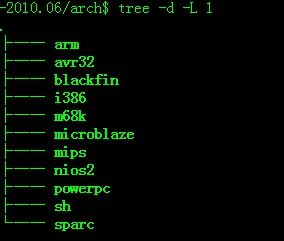
arch目录内容比以前的版本干净,每个子目录代表一个处理器类型,子目录名称就是处理器的类型名称。
我们移植的是mips的处理器,所以参考一下arch/mips目录:
arch/mips
├── cpu
├── include
└── lib
arch/mips目录下有三个目录,其他的处理器目录下也是这个结构:
cpu子目录对应一种处理器的不同产品型号或者系列;
include子目录是处理器用到的头文件;
lib目录对应用到处理器公用的代码;
下面看看cpu下的内容,arch/mips/cpu目录下的内容:
arch/mips/cpu/vr9
目前最新版本(2011.6版本开始)中cpu目录中建立mips32目录,把u-boot.lds是ld程序也就是连接器的脚本文件,这个文件描述了如何连接目标文件,ld程序会根据这个文件的指示按照需求把不同的目标文件连接在一起生成供烧写到开发板的程序。该文件放在board对应的目录中。
注意:如果公司需要升级U-Boot,则源代码下载地址
免费下载地址在 http://linux.linuxidc.com/
用户名与密码都是www.linuxidc.com
具体下载目录在 /pub/u-boot/
或 http://linux.linuxidc.com/pub/u-boot/
用户名与密码都是www.linuxidc.com
所有版本的u-boot源代码压缩包都可以在ftp://ftp.denx.de/pub/u-boot/下载。
关于u-boot源代码的信息,看http://www.denx.de/wiki/U-Boot/SourceCode码下载
二:uboot参考修改
大麦盒子用的uboot用的是vr9的标准板,其实不用更改,如果想要自己参考vr9的信息,我们可以做出一款自己的标准板,如(dm1),
$ cd board/vr9/
$ cp ../vr9 ../dm1 –a
$cd dm1
$ mv vr9.c dm1.c
$ vim Makefile
****************************
24 include $(TOPDIR)/config.mk
25
26 LIB = $(obj)lib$(BOARD).a
28 COBJS = $(BOARD).o
29 SOBJS = lowlevel_init.o
************************************
查看config.mk
********************************
24 -include $(TOPDIR)/.config
25
26 TEXT_BASE = $(CONFIG_RAM_TEXT_BASE)
***********************************
查看Kconfig
*********************************
把VR9的字符全都换成md1
********************************
修改u-boot顶层目录下的Makefile,按照vr9的内容添加md1的内容
*****************************
3423 vr9_config: unconfig
3424 @$(MKCONFIG) $(@:_config=) mips mips vr9
3425 @ln -s -f vr9_cfg.h include/configs/lq_cfg.h
3426 @ln -s -f vr9_cfg.h include/configs/ifx_cfg.h
****************************
在这后面添加同样的信息,把vr9改为md1
修改编译器 u-boot顶层目录下的Makefile
*************************************
191
192 # set default to nothing for native builds
193 ifeq ($(HOSTARCH),$(ARCH))
194 CROSS_COMPILE ?= (添加你所用到的编译器)
****************************
编译u-boot-2010.06 u-boot顶层目录
***************************
$ make distclean
$ make md1_config
$ make
***************************
这个时候我们就可以得到一个u-boot.bin也就是我们的目标文件,但是这个文件通常情况下是不能够正常工作的,我们还需要对u-boot源代码进行进一步的修改。
注意:下面的修改我只提供具体的修改办法,因为这个我没有继续修改下去,不过这个方法是验证过的。
1、u-boot源码中的中断屏蔽位的修改
问题:在md1中的子中断屏蔽位是否和vr9相同?
如果不同,则将arch/mips/cpu/vr9/start.S修改
- 修改配置文件include/configs/vr9.h
- 命令行提示符的修改:
**********************
112 #define CONFIG_SYS_LONGHELP /* undef to save memory */
113 #define CONFIG_SYS_PROMPT "VR9 # " /* Monitor Command Prompt */
114 #define CONFIG_SYS_CBSIZE 1024 /* Console I/O Buffer Size */
115 #define CONFIG_SYS_PBSIZE (CONFIG_SYS_CBSIZE+sizeof(CONFIG_SYS_PROMPT)+16) /* Print Buffer Size *
*********************
vr9# 改为md1#
- 网络参数设置
Ip地址、启动参数、延迟等
- 内核加载地址的修改
这个就很简单了 load_addr 在哪,改你想要的
- Nand功能添加
对照include/config_cmd_default.h和include/config_cmd_all.h添加我们需要的相应功能。
- 同时支持nand、nor和spi启动
/include/configs/vr9.h
265 #ifdef CONFIG_BOOT_FROM_NOR
266 #define IFX_CFG_FLASH_DDR_CFG_START_ADDR 0xB000FFE0
267 #define IFX_CFG_FLASH_DDR_CFG_SIZE 32
268 #define IFX_CFG_FLASH_DDR_CFG_END_ADDR 0xb000ffff
269 #elif defined(CONFIG_BOOT_FROM_SPI)
270 #define IFX_CFG_FLASH_DDR_CFG_START_ADDR 0x0000FFE0
271 #define IFX_CFG_FLASH_DDR_CFG_SIZE 32 //32字节的启动
这个十分关键,如果第二次启动失败,则是这里的问题。
272 #define IFX_CFG_FLASH_DDR_CFG_END_ADDR 0x0000ffff
- 环境变量保存位置
ENV变量是否正确
- USB功能的添加
这个我没做,有必要可以做。
********************
#define CONFIG_CMD_FAT ???????????????/* FAT support*/
#define CONFIG_CMD_USB ????????????????/* USB support*/
#if defined(CONFIG_CMD_USB)
#define CONFIG_DOS_PARTITION
#define CONFIG_USB_OHCI
#define CONFIG_USB_STORAGE
#define CONFIG_SUPPORT_VFAT
#define LITTLEENDIAN
#endif
Ping命令的添加
#define CONFIG_CMD_PING ????????????????/* ping support*/
***************************
再给出一些参考的信息,这是我调试的一部分,具体验证根据各平台的不同验证。
/*********************设计 MIPS GRX390****************/
/****************************/
3、添加Nand启动功能 start.S
u-boot默认情况下是nand启动,这里我们添加nand启动的内容:
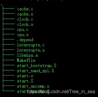
iq_xrx200_vrx288_gw_he_vdsl_lte/u-boot-2010.06/arch/mips/cpu/ar10$ ls
cache.c interrupts.c start_nand_spl.S
clock.c Makefile start.S
cpu.c start_bootstrap.S start_uncomp.S
1)添加头文件
26 #include
27 #include
28 #include
29 #include
30 #include
31 #include
32 #include
2)添加nand启动标志位
3)添加BWSCON寄存器的定义(加粗字体为添加内容)
4)添加启动模式判断Nor启动还是nand启动(加粗字体为添加内容)
5)添加NAND启动自搬移代码(在上一步代码下添加)
4、添加nand_read.c为nand启动做支持
5、修改board/ar10/?支持 nor flash芯片
x200_vrx288_gw_he_vdsl_lte/u-boot-2010.06/board/ar10$ ls
ar10.c ddr2_16bit.conf Kconfig sfddr_board.c
bootstrap.lds ddr2_8bit.cmm lowlevel_init.S start_sfddr.S
config.mk ddr2_8bit.conf Makefile stools.c
ddr1 ddr.h Makefile.lq u-boot.lds
ddr2 gphy_firmware.img nand_spl_board.c
6、修改common/env_flash.c,为nor flash保存环境变量做准备
7、修改common/env_nand.c添加nor flash环境变量烧写功能
8、修改SDRAM刷新周期:board/ar10/lowlevel_init.S
239 #if defined(CONFIG_AR10_PPE_FREQ_468M) || defined(CONFIG_GRX390_CPU_720M_
240 defined(CONFIG_GRX390_CPU_360M_RAM_360M) || defined (CONFIG_GRX390_CP
241 defined(CONFIG_GRX390_CPU_180M_RAM_180M) /* change for 720Mhz & PPE c
9、链接文件的修改/arch/mips/cpu/ar10/*************?/ u-boot.lds:
rx200_vrx288_gw_he_vdsl_lte/u-boot-2010.06/arch/mips/cpu/ar10$ ls
cache.c cpu.c Makefile start_nand_spl.S start_uncomp.S
clock.c interrupts.c start_bootstrap.S start.S
10、go命令的优化
3、重新编译
$ make distclean
$ make grx390_config
$ make
篇 二
篇二介绍了大麦盒子怎样根据大麦盒子的硬件需求,介绍了demo版默认的uboot从NAND Flash启动方式转变为SPI Flash启动的配置更改,具体的步骤在这里面会有详细的介绍,如果以后的开发和维护遇到相同的问题,可以尽可能的节约时间去研究这些内容。
一:菜单配置uboot选项
分析:我们的大麦盒子根据自己的spi Flash winbond的W25Q128芯片进行修改,我们修改的过程如下:
1、Make menuconfig打开界面选择Boot Loaders
Kernel modules --->
Benchmarks --->
Boot Loaders ---> uCI2 --->
2、在Boot Loaders下选择Configuration
gpon-uboot --->
--- open_uboot................. U-Boot for Lantiq SoC based platforms
Configuration --->
[ ] uboot-tqm8315........ U-Boot for Lantiq PowerQUICC II based boards
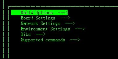
3、Configuration的菜单界面如下
我们的主要工作便是修改这个里面的东西,
1)在Build Options中
选择boot的启动方式,我们选择spi Flash ,
选择OS交叉编译的类型LZMA 。
2)在Board Setting中
- RAM Size(M) 根据RAM大小设定。
(115200) ASC BAUDRATE 串口波特率
---SPI FLASH SUPPORT
SPI Flash Size(M) (16M) ---> 选择spi flash的大小
[*] WINBOND SFLASH SUPPORT 选择spi flash芯片厂商
(3) SFLASH SPI MODE spi flash模式
[*] overlay fs support
CPU/DDR FREQUENCY ---> CPU的频率
[*] DDR tuning support DDR调整,与硬件的DQS关系密切
3)在Network Settings中
(192.168.2.62) IP address
(192.168.2.61) Server IP address
(00:E0:92:00:01:40) Ethernet Address
(eth0) Ethernet Interface
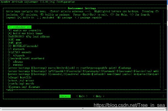
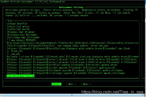
- 在Environment Setting中
这个通常根据硬件的不同修改的程度比较大,我修改的地方如下,而这个文件也是与U-boot-2010.06/include/configs/lq_cfg.h添加16Mflash 的分区表密切相关的。
- 在libs中选择
仅仅列出一些,根据需要勾选
[*]ZLIB [*]RBTREE [*]LZO
[*] LZMA
- 在Supported commands中选择需要的命令
仅仅列出一些,根据需要勾选
[*] echo
[*] httpd
[*] mem
[*] net
[ ] ubi 去掉这个选项
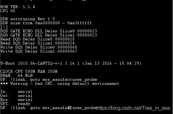
二:uboot的制造商的校验
分析:我们的大麦盒子用的不是demo上的spi flash的芯片,因此,编译后的uboot可能会产生制造商的校验错误,芯片是不会识别的。
这是error信息 "SF: !flash, goto err_manufacturer_probe”
在程序中grep -rn err_manufacturer_probe ./ 可以定位 /drivers/mtd/spi/winbond.c
170 default:
171 debug("SF: Unsupported manufacturer %02X\n", idcode[0]);
172 flash = NULL;
173 break;
174 }
175
176 if (!flash) {
177 printf("SF: !flash, goto err_manufacturer_probe\n");
178 goto err_manufacturer_probe;
179 }
我们用的spi flash 的芯片型号是w25q128 ,它的制造商为winbond,所以在改目录下的winbond.c中加上我们的信息,根据该芯片的datasheet的ID,页等等添加该芯片的信息。
定位SPI芯片 winbond.c W25Q128 16M
添加如下信息
18 #define CMD_W25_READ 0x03 /* Read Data Bytes */
30 #define WINBOND_ID_W25Q64 0x4017
31 #define WINBOND_ID_W25Q128 0x4018 datasheet 描述
89 {
90 .id = WINBOND_ID_W25Q128,
91 .l2_page_size = 8,
92 .pages_per_sector = 16,
93 .sectors_per_block = 16,
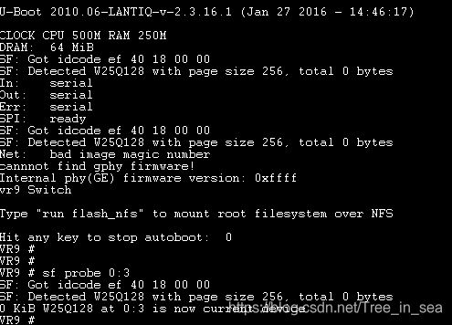
94 .nr_blocks = 256, 这个是他们的bug
95 .name = "W25Q128"
96 },
把common/cmd_sf.c中的函数
有关Probe 和winbond的函数调试信息打开
定位到了256 这个大小在uint8_t
nr_blocks; 只记到了255,没有记到256 ,因此打印为0. U
int8_t 改为 uint16_t
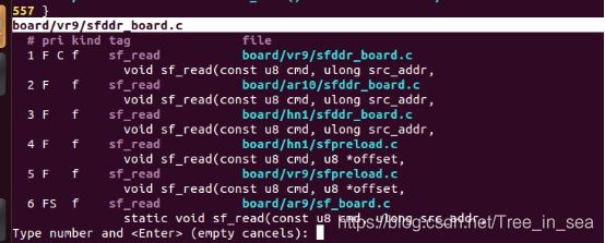
******定位到board/vrq/sfddr_board.c 你可以修改,也可以不修改,因为这个文件不起决定作用。
271 #define CMD_MX25L_READ 0x03
272 #define CMD_S25FLXX_READ 0x03
273 #define CMD_W25_READ 0x03 / 添加更好,不添加也不要紧、
494 int i;
495 u8 cmd = CMD_MX25L_READ; /修改 、 u8 cmd = CMD_W25_READ 修改更好,不添加也不要紧、
496 size_t addr_len = 3;
同时支持nand、nor和spi启动
/include/configs/vr9.h
265 #ifdef CONFIG_BOOT_FROM_NOR
266 #define IFX_CFG_FLASH_DDR_CFG_START_ADDR 0xB000FFE0
267 #define IFX_CFG_FLASH_DDR_CFG_SIZE 32
268 #define IFX_CFG_FLASH_DDR_CFG_END_ADDR 0xb000ffff
269 #elif defined(CONFIG_BOOT_FROM_SPI)
270 #define IFX_CFG_FLASH_DDR_CFG_START_ADDR 0x0003FFE0
271 #define IFX_CFG_FLASH_DDR_CFG_SIZE 32 //32字节的启动
这个十分关键,如果第二次启动失败,则是这里的问题。
272 #define IFX_CFG_FLASH_DDR_CFG_END_ADDR 0x0003ffff
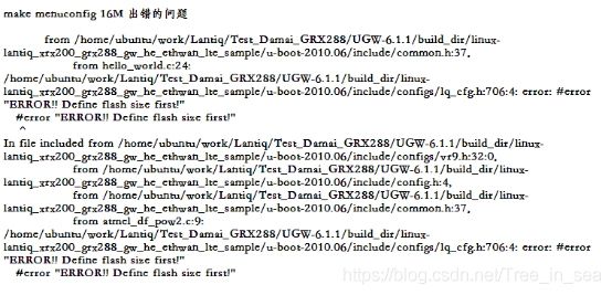
三:16M Flash添加的问题
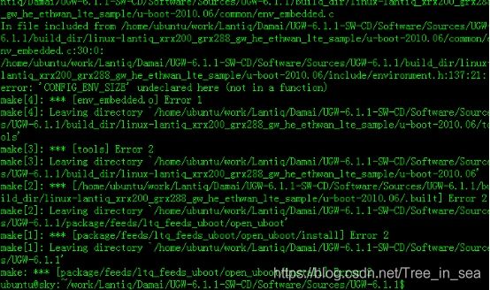
由于默认的u-boot-2010.06/include/configs/lq_cfg.h未添加16M SPI flash芯片的分区表,我们编译的时候会出现如下的error信息:
此刻,我们需要的是在
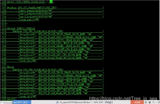
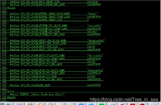
U-boot-2010.06/include/configs/lq_cfg.h添加16Mflash 的分区表
添加如下:
498 #elif CONFIG_SPI_FLASH_16M
499 #define IFX_CONFIG_FLASH_SIZE 16
添加info信息和part分区开始地址;
开始添加各个分区情况;
当然,在以下的地方也同样更改,对应着更改就行了。
1057 #elif (IFX_CONFIG_FLASH_SIZE == 16)
1058 #if !defined( CONFIG_VR9_GPHY_FW_EMBEDDED )
1059 #define IFX_CFG_FLASH_PARTITIONS_INFO \
1060 "part0_begin=0x00000000\0" \
1061 "part1_begin=0x00010000\0" \
1062 "part2_begin=0x00020000\0" \
1063 "part3_begin=0x000A0000\0" \
1064 "total_part=4\0"
1065 #else
1066 #define IFX_CFG_FLASH_PARTITIONS_INFO \
1067 "part0_begin=0x00000000\0" \
1068 "part1_begin=0x00020000\0" \
1069 "part2_begin=0x000A0000\0" \
1070 "total_part=3\0"
1071 #endif
..............................................
这时候编译uboot是成功的,但是还有一个问题,那么就是网络的问题,我们需要网络去下载镜像文件。
四:网口GPHY固件的问题
我们用的是CPU内置PHY进行调试的,而demo板使用的是独立出PHY进行调试的,所以我们需要的修改以下的地方。
1. 将UGW-6.1.1/bin/lantiq/vrx288_rt_el_vdsl/gphy_firmware.img内容另存为一个数组,放在一个h文件中。
你可以用bin2c工具来做,也可以用ultraedit或类似工具来手动改。
把这个数组命名为“xrx200_PHY_Firmware_FE_RC434.h”
- 将附件拷贝进文件夹UGW-6.1.1/build_dir/linux-lantiq_xrx200_vrx220_rt_el_vdsl/u-boot-2010.06/drivers/net
- 修改vr9_sw.c 文件的函数
vr9_sw_chip_init()
……
#include "xrx200_PHY_Firmware_FE_RC434.h"
fw_src_addr = (u32) xrx200_PHY_Firmware_FE_RC434;
if(get_gphy_firmware(fw_addr,fw_src_addr)){
printf("cannnot find gphy firmware!\n");
}
……
![]()
- 编译,下载,检查PHY firmware的版本号由0xffff变为0x8435
make package/feeds/ltq_feeds_uboot/open_uboot/install V=s
把uboot中的NAND中的支持命令的[]ubi的命令给去掉
xrx200_ddr2_197_CAS4_config.conf (board/vr9/)
./scripts_platform/gct xrx200_ddr2_197_CAS4_config.conf u-boot.srec u-boot.asc
注意:制作uboot.asc把这些信息添加进去,如果需要烧录的uboot.ltq,则把这些信息屏蔽掉,再次编译生成uboot.ltq。
篇 三
对uboot的调试其实并不难,主要注意的问题是在以下几个地方。
硬件上:你的板子上是哪一款芯片,大小多少,ID多少,页与块的设置。
软件上:uboot的环境参数的配置,uboot的分区表,uboot软件上对硬件的支持。
Log信息如下:
VR9 # run update_uboot
Using vr9 Switch device
TFTP from server 192.168.2.61; our IP address is 192.168.2.62
Filename 'u-boot.ltq'.
Load address: 0x80800000
Loading: T ##############
done
Bytes transferred = 196134 (2fe26 hex)
16384 KiB W25Q128 at 0:3 is now current device
Erasing SPI flash...Erase: 20 00 00 00
Erase: 20 00 10 00
Erase: 20 00 20 00
Erase: 20 00 30 00
Erase: 20 00 40 00
Erase: 20 00 50 00
Erase: 20 00 60 00
Erase: 20 00 70 00
Erase: 20 00 80 00
Erase: 20 00 90 00
Erase: 20 00 a0 00
Erase: 20 00 b0 00
Erase: 20 00 c0 00
Erase: 20 00 d0 00
Erase: 20 00 e0 00
Erase: 20 00 f0 00
Erase: 20 01 00 00
Erase: 20 01 10 00
Erase: 20 01 20 00
Erase: 20 01 30 00
Erase: 20 01 40 00
Erase: 20 01 50 00
Erase: 20 01 60 00
Erase: 20 01 70 00
Erase: 20 01 80 00
Erase: 20 01 90 00
Erase: 20 01 a0 00
Erase: 20 01 b0 00
Erase: 20 01 c0 00
Erase: 20 01 d0 00
Erase: 20 01 e0 00
Erase: 20 01 f0 00
Erase: 20 02 00 00
Erase: 20 02 10 00
Erase: 20 02 20 00
Erase: 20 02 30 00
Erase: 20 02 40 00
Erase: 20 02 50 00
Erase: 20 02 60 00
Erase: 20 02 70 00
Erase: 20 02 80 00
Erase: 20 02 90 00
Erase: 20 02 a0 00
Erase: 20 02 b0 00
Erase: 20 02 c0 00
Erase: 20 02 d0 00
Erase: 20 02 e0 00
Erase: 20 02 f0 00
Erase: 20 03 00 00
Erase: 20 03 10 00
Erase: 20 03 20 00
Erase: 20 03 30 00
Erase: 20 03 40 00
Erase: 20 03 50 00
Erase: 20 03 60 00
Erase: 20 03 70 00
Erase: 20 03 80 00
Erase: 20 03 90 00
Erase: 20 03 a0 00
Erase: 20 03 b0 00
Erase: 20 03 c0 00
Erase: 20 03 d0 00
Erase: 20 03 e0 00
Erase: 20 03 f0 00
Done
Erase: 20 00 00 00
Erase: 20 00 10 00
Erase: 20 00 20 00
Erase: 20 00 30 00
Erase: 20 00 40 00
Erase: 20 00 50 00
Erase: 20 00 60 00
Erase: 20 00 70 00
Erase: 20 00 80 00
Erase: 20 00 90 00
Erase: 20 00 a0 00
Erase: 20 00 b0 00
Erase: 20 00 c0 00
Erase: 20 00 d0 00
Erase: 20 00 e0 00
Erase: 20 00 f0 00
Erase: 20 01 00 00
Erase: 20 01 10 00
Erase: 20 01 20 00
Erase: 20 01 30 00
Erase: 20 01 40 00
Erase: 20 01 50 00
Erase: 20 01 60 00
Erase: 20 01 70 00
Erase: 20 01 80 00
Erase: 20 01 90 00
Erase: 20 01 a0 00
Erase: 20 01 b0 00
Erase: 20 01 c0 00
Erase: 20 01 d0 00
Erase: 20 01 e0 00
Erase: 20 01 f0 00
Erase: 20 02 00 00
Erase: 20 02 10 00
Erase: 20 02 20 00
Erase: 20 02 30 00
Erase: 20 02 40 00
Erase: 20 02 50 00
Erase: 20 02 60 00
Erase: 20 02 70 00
Erase: 20 02 80 00
Erase: 20 02 90 00
Erase: 20 02 a0 00
Erase: 20 02 b0 00
Erase: 20 02 c0 00
Erase: 20 02 d0 00
Erase: 20 02 e0 00
Erase: 20 02 f0 00
16384 KiB W25Q128 at 0:3 is now current device
Erasing SPI flash...Erase: 20 fe c0 00
Erase: 20 fe d0 00
Erase: 20 fe e0 00
Erase: 20 fe f0 00
Erase: 20 ff 00 00
Erase: 20 ff 10 00
Erase: 20 ff 20 00
Erase: 20 ff 30 00
Erase: 20 ff 40 00
Erase: 20 ff 50 00
Erase: 20 ff 60 00
Erase: 20 ff 70 00
Erase: 20 ff 80 00
Erase: 20 ff 90 00
Erase: 20 ff a0 00
Erase: 20 ff b0 00
之后遇到这些问题
1、然后定位DDR tuning的文件u-boot-2010.06/board/vr9/sfddr_board.c
grep -rn “gphy_firmwate” ./
2、Uboot的大小copy 0x10000 改为 0x40000
3、注释gphy firmware 550行
Ok 现在已经是可以用的uboot了
那么我们去优化一些信息
4、把lantiq的主机名换成Centnet
在include/configs/lq_extra_env.h中添加
"hostname=Centnet\0" 这是linux系统起来后使用的主机名
5. bootargs后添加do_overlay
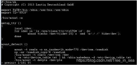
起来后,会执行脚本/etc/preinit,重新挂载文件系统。将data分区挂载到/overlay(非常规文件)目录下,所有修改的数据都会在data分区保存,可以在overlay目录下看到。
6. 分区表中添加data分区,系统起来后,以jffs2挂载data分区到/overlay目录下
注意:data分区的起始地址和长度必须是erase_size的整数倍否则使用flash_erase失败
build_dir/target-mips_r2_uClibc-0.9.33.2_grx288_gw_he_ethwan_lte_sample/mtd-utils-1.4.6/flash_erase.c文件中以字符设备方式打开data分区:
if ((fd = open(mtd_device, O_RDWR)) < 0)
return sys_errmsg("%s", mtd_device);
参照文章:http://blog.chinaunix.net/xmlrpc.php?r=blog/article&uid=29616823&id=4584240
7. 优化flash读写擦除操作的打印信息
drivers/mtd/spi/winbond.c
把擦除信息屏蔽掉,例如 需要添加头文件(如果想用这情形,则按照你想要的情况做出修改)
注释:uboot改变参数的时候
Sf probe 0:3
Sf erase (f_ubootconfig_addr) (f_ubootconfig_size)
Run update_uboot
对象:u-boot (UGW-6.1.1 )
版本:2010.06-LANTIQ-v-2.2.x
make menuconfig
Boot Loaders --->
open_uboot.........
configure --->
目标目录是在build_dir/linux-ifxcpe_platform_(platform)/u-boot-2010.06,最后的产品 u-boot.ltq 复制到 bin/ltqcpe/(platform) 目录。
在OpenWRT 中独立编译 u-boot
#make package/feeds/ifx_feeds_uboot/open_uboot-{clean,compile,install} V=99
编译u-boot目录((build_dir/linux-ifxcpe_platform_(platform)/u-boot-2010.06))
#make (platform)_config (platform could be danube/amazon_se/ar9/vr9)
#make menuconfig
#make clean all
通过make menuconfig 菜单系统配置u-boot
Boot Loaders --->
open_uboot.........
configure --->
Build Options --->
Board Settings --->
Networking Settings --->
Envrionment Settings --->
Supported commands --->
设置Boot模式
Build Options --->
Boot From --->
[] NOR Flash
[] SPI Flash
[] NAND Flash
[] ETHERNET
[] UART
[] NO Flash
boot 模块镜像
?NOR Flash: u-boot.lq 00001
?SPI Flash: u-boot.lq 00101
?NAND Flash: u-boot-nand.bin 00110
?UART: u-boot.asc 00100
?ETHERNET: u-boot.asc 10000
?NO FLASH: u-boot.asc (仅用于调试)
设置RAM大小
设置NOR Flash大小
选择SPI Flash NAND Flash NOR Flash 支持
Board Settings --->
(64)RAM Size(M)
(115200) ASC BAUFRATE x x
[ ] NOR FLASH SUPPORT x x
[ ] SPI FLASH SUPPORT x x
[ ] SPI EEPROM SUPPORT x x
--- NAND FLASH_SUPPORT x x
ECC MODE (SOFTWARE HAMMING) ---> x x
[ ] BAD NAND BLOCK SCAN x x
NAND Flash Size(M) (256M) ---> x x
(0x800) NAND flash page size(bytes in hex) x x
(0x40000) NAND flash erase block size(bytes in hex) x x
(0x5000) NAND SPL IMAGE SIZE(bytes in hex) x x
[*] nand mini loader x x
[ ] nand spl bbt support x x
[*] firmware in rootfs x x
[ ] overlay fs support x x
CPU/DDR FREQUENCY ---> x x
SWITCH OPTIONS ---> x x
[*] DDR tuning support x x
[*] ENABLE_DCDC x x
[*] POWER DOWN 2.5V REGULATOR x x
[ ] CHECK PLL2 LOCK x x
[ ] ON PALLADIUM
设置网络设定
Networking Settings --->
(192.168.1.1) IP address
(192.168.1.2) Server IP address
(00:E0:92:00:01:40) Ethernet Address
(eth0) Ethernet Interface
设置环境变量
Envrionment Settings --->
(0x4000) env size x x
x x [*] redundant env x x
x x [*] enable env overwrite x x
x x [*] build env block image x x
x x (0x80800000) tftp load address x x
x x (63M) mem x x
x x (64M) phym x x
x x (5) BOOTDELAY(seconds) x x
x x (/mnt/full_fs) rootpath x x
x x (ttyLTQ0) console x x
x x () tftppath x x
x x (/dev/mtdblock3) rootfsmtd x x
x x (setenv bootargs ubi.mtd=system_sw root=/dev/nfs rw nfsroot=$(serverip):$(rootpath)) nfsargs x x
x x (setenv bootargs root=/dev/ram rw) ramargs x x
x x (setenv bootargs ubi.mtd=system_sw rootfsname=$(rootfsname) ro rootfstype=squashfs quiet) flashargs x x
x x (setenv bootargs $(bootargs) ip=$(ipaddr):$(serverip):$(gatewayip):$(netmask):$(hostname):$(netdev):on) addip x x
x x (setenv bootargs $(bootargs) console=$(console),$(baudrate) ethaddr=$(ethaddr) phym=$(phym) mem=$(mem) panic=1 $(mtdpartx x
x x (uImage) bootfile x x
x x (u-boot.ltq) u-boot x x
x x (rootfs.img) rootfs x x
x x (firmware.img) firmware x x
x x (fullimage.img) fullimage x x
x x (totalimage.img) totalimage x x
x x (nand0=ifx_nand) mtdids x x
x x [ ] use default MTDPARTS x x
x x (mtdparts=ifx_nand:1024k(uboot),256k(ubootconfigA),256k(ubootconfigB),256k(gphyfirmware),200m(system_sw),1m(calibration)x x
x x (tftp $(loadaddr) $(tftppath)$(bootfile); run ramargs addip addmisc; bootm) net_ram
启动Linux内核和根文件系统,u-boot需要做以下步骤:
?编写内核和文件系统映像到适当的位置。
?和解压内核映像复制到RAM。
?把适当的内核参数在相应位置,跳转到内核地址和执行内核代码。
?为了达到这个目的,u-boot编译和操作内核需要做一定的准备。
?用户需要修改(platform)_cfg.h改变内核的分区映射。
二 :更新镜像
在include/image.h的头文件下,定义了
开发板操作系统
开发板CPU架构
压缩类型
加载地址
入口
镜像名称
镜像时间戳
头部被一种特别的数字标记,头和镜像数据区需要CRC232校验
编译UGW的u-boot镜像
应用程序 “mkimage” u-boot/tools/ directory
作用: 添加文件镜像的特殊头部
使用方式
Usage: tools/mkimage -l image
?-l ==> list image header information
?tools/mkimage [-x] -A arch -O os -T type -C comp -a addr -e ep -n name -d data_file[:data_file...] image
?-A ==> set architecture to ‘arch’
?-O ==> set operating system to ‘os’
?-T ==> set image type to ‘type’
?-C ==> set compression type ‘comp’
?-a ==> set load address to ‘addr’ (hex)
?-e ==> set entry point to ‘ep’ (hex)
?-n ==> set image name to ‘name’
?-d ==> use image data from ‘datafile’
?-x ==> set XIP (execute in place)
生成UGW u-boot镜像的步骤如下
Table 1 Kernel Image
Image type kernel image
Image name ulmage
File needed vmlinux.lzma
Info needed kernel load address, kernel entry address
Command example mkimage -A mips -O linux -T kernel -a 0x80002000 -C
lzma -e 0xFFFFFFFF80319000 -n 'MIPS IFXCPE Linux-
2.6.20.19' -d vmlinux.lzma uImage
Table 2 Root File System
Image type root file system
Image name rootfs.img
File needed root.squashfs
Info needed None
Command example mkimage -A MIPS -O Linux -C lzma -T filesystem -e 0x00
-a 0x00 -n "IFXCPE RootFS" -d root.squashfs rootfs.img
Table 3 fullimage (kernel+rootfs)
Image type fullimage (kernel+rootfs)
Image name fullimage.img
File needed uImage, rootfs.img
Info needed None
Command example cat rootfs.img > fullimage.tmp
cat uImage > fullimage.tmp
mkimage -A MIPS -O Linux -C none -T multi -e 0x00 -a
0x00 -n "AR9 Fullimage" -d fullimage.tmp fullimage.img
Table 4 u-boot Image (for totalimage)
Image type u-boot image (for total image)
Image name u-bootimg.ifx
File needed u-boot.ifx
Info needed None
Command example mkimage -A mips -T uboot -C lzma -a 0x00 -e 0x00 -n 'UBoot
Img' -d u-boot.ifx u-bootimg.ifx
Table 5 totalimage (u-boot+rootfs_kernel)
Image type totalimage (u-boot+rootfs+kernel)
Image name totalimage.img
File needed u-boot.ifx rootfs.img uImage
Info needed None
Command example cat u-bootimg.ifx > totalimage.tmp
cat rootfs.img > totalimage.tmp
cat uImage > totalimage.tmp
mkimage -A MIPS -O Linux -C none -T multi -e 0x00 -a
0x00 -n "AR9 Fullimage" -d totalimage.tmp totalimage.img
使用控制台命令
?update_kernel = tftpboot $(loadaddr) $(bootfile); upgrade kernel $(loadaddr) $(filesize)
?update_rootfs = tftpboot $(loadaddr) $(rootfs); upgrade rootfs $(loadaddr) $(filesize)
?update_firmware = tftpboot $(loadaddr) $(firmware); upgrade firmware $(loadaddr) $(filesize)
升级功能被定义在ifx_cfg.h中,用户可以在编译的menuconfig系统中更改这些脚本
User can run these scripts in u-boot console by typing:
?#run update_kernel → update kernel image using “uImage”
?#run update_rootfs → update rootfile system using “rootfs.img”
?#run update_firmware → update firmware using “firmware.img”
?#run update_fullimage → update fullimage (rootfs+kernel (+firmware)) using “fullimage.img”
?#run update_totalimage → update totalimage (u-boot + rootfs + kernel (+firmware)) using “totalimage.img”
更新镜像的先决条件校验
这些信息携带不同的版本信息和名字主要是与硬件有关。启用此功能,用户需要选择。
Build Options --->
[]IFX EXTRA IMAGE CHECK
一旦启用了这个选项,“mkimage”功能程序能够接受新的参数如供应商名称,名称,版本,芯片的名字,芯片版本和软件版本和把它们放在镜像的头信息前面。
The additional options for “mkimage” are:
?Usage: tools/mkimage
–-B ==> set vendor name
–-V ==> set board name
–-b ==> set board version
–-c ==> set chip name
–-p ==> set chip version
–-s ==> set software version
Table 6 Examples of Sanity Check Status
From u-boot From Image to Upgrade
ih_vendor = “ABC” ih_vendor = “ABC”
ih_board = ”EASY50813” ih_board = ”EASY50813”
ih_boardVer = ”1.23” ih_boardVer = ”1.23” Sanity check status : Pass
ih_chip = ”ARX168” ih_chip = ”ARX168”
ih_chipVer = ”1.2” ih_chipVer = ”1.2”
ih_swVer = ”4.1.0” ih_swVer = ”4.1.0”
Table 8 Examples of Sanity Check Status
From u-boot From Image to Upgrade
ih_vendor = “ABC” ih_vendor = “ABC”
ih_board = ”EASY50813” ih_board = ”EASY50813”
ih_boardVer = ”1.23” ih_boardVer = ”1.20” Sanity check status : Fail
ih_chip = ”ARX168” ih_chip = ”ARX168”
ih_chipVer = ”1.2” ih_chipVer = ”1.2”
ih_swVer = ”4.2.0” ih_swVer = ”3.7.0
fullimage加额外头信息的例子
mkimage -A MIPS -O Linux -C none -T multi -e 0x00 -a 0x00 \
?-B 'LANTIQ' -V 'EASY50812' -b '1.23' -c 'ARX188' -p '1.2' -s '4.2.0' \
?-n "AR9 Fullimage" -d fullimage.tmp fullimage.img
然而,由于附加信息,标题大小改变。它将需要一个u-boot由选择额外的图像检查选项能够解码镜像与额外的头信息。否则,u-boot镜像不能识别。
使用串口更新升级镜像
有时,用户可能需要一个图像从UART接口下载flash镜像时损坏。这镜像将负责
?提供RAM配置ROM代码。
?提供一个ROM代码到u-boot镜像。
?提供的u-boot镜像的开始位置
两个文件必须需要:RAM配置文件,,另一个是u-boot.srec
RAM配置文件应写在(地址值)格式,参考以下
?0xbf800060 0xf
?0xbf800010 0x0
?0xbf800020 0x0
?0xbf800200 0x02
“值”将被一个接一个的ROM代码会写入“地址”。
用户将需要使用scripts_platform/下面的gct 结合RAM配置文件和u-boot.srec
UART下载镜像将生成如下
#./scripts_platform/gct ram.conf u-boot.srec u-boot.asc
u-boot.asc是UART下载图像。不同的平台有不同的RAM配置文件。
用户可能需要检查硬件规范知道应该写在RAM配置文件。有一些预先写好的RAM配置文件UGW u-boot目录了。用户可能需要他们的
?XWAY? DANUBE: (u-boot)/board/danube/danube_ref_ddr166.conf
?XWAY? AMAZON-SE: (u-boot)/board/amazon_se/ram.conf
?XWAY? ARX100: (u-boot)/board/amazon_s/ram.conf
?XWAY? VRX200:
–(u-boot)/board/vr9/xrx200_ddr1_197_config.conf (for ddr1)
–(u-boot)/board/vr9/xrx200_ddr2_197_CAS4_config.conf (for ddr2)
?XWAY? xRX300: (u-boot)/board/ar10/ddr2_16bit.conf
用户有必要改变配置文件根据用户的DDR规格。不同的DDR模型可能需要不同的配置文件时间参数,等等。
在编译镜像之后,用户需要把引导设置为“从UART引导”模式。开发板中下面的消息将会在控制台上打印:
ROM VER: 1.0.0
CFG 04
UART
Linux? to send the “asc” file to the console (assuming that the console is in /dev/ttyS0):
#cat u-boot.asc |xargs echo >/dev/ttyS0
发送此命令后,bootrom将打印的一系列“*”表示正在进行下载
使用网页升级镜像
用户还可以选择使用Web页面更新图像。u-boot所需的HTTP服务器的功能是使网页升级。要启用HTTP服务器
Supported commands --->
[ ] fpga x x
x x [*] httpd x x
x x [ ] i2c x x
x x [ ] ide x x
x x [ ] immap x x
x x [ ] itest
编译后,HTTP服务器嵌入u-boot图像。用户需要输入“# httpd”
u-boot控制台启动HTTP服务器。
打开Internet浏览器
输入“http://(ip address of the board)”
点击 Upload
点击 Update
点击 go back完成
使用串口升级镜像
用户可以使用串口下载镜像到开发板的RAM中,必须要使用loadb命令
Supported commands --->
[ ] fdc x x
x x [ ] libfdt x x
x x [*] loadb x x
x x [ ] loads
敲入“#loadb 80400000 115200”.
在超级终端中select Transfer → Send File.
选择“Kermit”作为传输协议
点击发送这个文件内核
传输之后,镜像位于0x80400000 这个位置,用户可以拷贝需要的镜像到flash区域
MTD分区挂载内核
The format of “mtdparts” can be obtained from the kernel file drivers/mtd/cmdlinepart.c.
Some default values for “mtdparts” are set in (u-boot dir)/scripts_platform/Kconfig.
用户根据自己的目的修改这些值,同时也要保证内核的配置参数
用户需要设定rootfsmtd(/dev/mtdblock1, etc)通知内核和根文件系统的MTD分区号
重要的内核参数
这些内核参数对于内核来说至关重要
?console → ttyS0/ttyS1 (ttyS0 for XWAY? AMAZON-SE and XWAY? VRX200, ttyS1 for XWAY? DANUBE and XWAY? xRX300).
?mem → The size of the RAM that will be used by Linux? kernel.
?phym → The actual size of physical RAM. Usually, will be slightly bigger than mem for VOIP firmware.
?rootpath → The network file system root path.
?tftppath → The tftp path in the tftp server.
DDR 对u-boot自动调整特性
Select Board Settings → DDR tuning support
x x [ ] overlay fs support x x
x x CPU/DDR FREQUENCY ---> x x
x x SWITCH OPTIONS ---> x x
x x [*] DDR tuning support x x
x x [*] ENABLE_DCDC
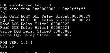
在板子第一次运行时,这个调整程序会最终找到正确的参数
一旦优化过程完成后,u-boot将照常启动和调整正确参数将存储在flash。可以删除在flash存储的DDR正确调整参数。
调优参数再次进入u-boot控制台,输入“运行reset_ddr_config”。
用户可以改变DDR在Flash中的配置位置,在include/configs/(platform).h中
?#define IFX_CFG_FLASH_DDR_CFG_START_ADDR - 0xB000FFE8
?#define IFX_CFG_FLASH_DDR_CFG_SIZE - 24
?#define IFX_CFG_FLASH_DDR_CFG_END_ADDR - 0xb000FFFF
u-boot env备份特性
select Environment Settings → redundant
x x (0x4000) env size x x
x x [*] redundant env x x
x x [*] enable env overwrite x x
x x [*] build env block image
u-boot env镜像单独编译在flash中
select Environment Settings → redundant
在系统建立之前将环境变量镜像写入flashes
x x (0x4000) env size x x
x x [*] redundant env x x
x x [*] enable env overwrite x x
x x [*] build env block image
这个镜像为“ubootenv”
UBI支持
这是IBM的新技术,受GPL许可保护
这是一个LVM(逻辑卷管理)在嵌入式设备上。UBI使用原始的flash设备在单一的flash设备中管理多个逻辑卷,并且分离通过flash芯片的输入、输出负载
For NOR models, we use squashfs in rootfs and firmware images
For NAND, we used JFFS2 images for managing bad blocks
By moving to UBI on NAND chips, still we can use squashfs images on UBI volumes,

