HDLbits答案更新系列17(3.2.5 Finite State Machines 3.2.5.24 Q3a: FSM等)
目录
前言
3.2.5 Finite State Machines
3.2.5.24 Q3a: FSM(Exams/2014 q3fsm)
3.2.5.25 Q3b: FSM(Exams/2014 q3bfsm)
3.2.5.26 Q3c: FSM logic(Exams/2014 q3c)
结语
HDLbits网站链接
前言
今天继续更新几道题目,这几道题目很有技巧性,其中又有状态机加计数器的组合题,下面就让我们一起看看解题思想吧。
3.2.5 Finite State Machines
3.2.5.24 Q3a: FSM(Exams/2014 q3fsm)
module top_module (
    input clk,
    input reset,   // Synchronous reset
    input s,
    input w,
    output z
);

    parameter A = 1'b0, B = 1'b1;
    reg	        current_state;
    reg	        next_state;

    always@(posedge clk)begin
        if(reset)begin
            current_state <= A;
        end
        else begin
            current_state <= next_state;
        end
    end

    always@(*)begin
        case(current_state)
            A:begin
                next_state = s ? B : A;
            end
            B:begin
                next_state = B;
            end
        endcase
    end

    reg	w_reg1;
    reg w_reg2;
    always@(posedge clk)begin
        if(reset)begin
            w_reg1 <= 1'b0;
            w_reg2 <= 1'b0;
        end
        else if(next_state == B)begin
            w_reg1 <= w;
            w_reg2 <= w_reg1;
        end
        else begin
            w_reg1 <= 1'b0;
            w_reg2 <= 1'b0;
        end
    end

    always@(posedge clk)begin
        if(reset)begin
            z <= 1'b0;
        end
        else if(current_state == B && counter == 2'd0)begin
            if(~w & w_reg1 & w_reg2 | w & ~w_reg1 & w_reg2 | w & w_reg1 & ~w_reg2)begin
                z <= 1'b1;
            end
            else begin
                z <= 1'b0;
            end
        end
        else begin
            z <= 1'b0;
        end
    end

    reg [1:0]	counter;
    always@(posedge clk)begin
        if(reset)begin
            counter <= 2'd0;
        end
        else if(counter == 2'd2)begin
            counter <= 2'd0;
        end
        else if(next_state == B)begin
            counter <= counter + 1'b1;
        end
    end

endmodule
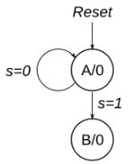
题意表明,当s为0时,进入B状态,然后会检查w的值,如果在接下来的三个周期中w值有两个周期都为1,那么z输出1,否则z输出0。注意,这里隐含的条件是不重叠检测,意味着每三个周期检查一次,周期与周期之间不重叠。
首先,我按照题目中给出的状态转移图写了基础的状态机模块;接着,用一个计数器进行计数,在状态B时,counter计数三次清零,然后循环;然后,我使用了类似边沿检测的方法,将w打了两拍,判定条件为三拍中两拍为高,如果满足条件,z输出1,否则输出0。
注意:这里counter的判定条件为counter == 2'd0,大家可以想一想,在next_state为B时counter加1,也就是current_state为A且s为1时counter就要等于1(三拍中的第一拍其实counter已经等于1了),而我们这里是将counter数三次然后清零,所以第三个周期是counter == 2'd0。
3.2.5.25 Q3b: FSM(Exams/2014 q3bfsm)
module top_module (
    input clk,
    input reset,   // Synchronous reset
    input x,
    output z
);

    parameter S0 = 3'd0, S1 = 3'd1, S2 = 3'd2;
    parameter S3 = 3'd3, S4 = 3'd4;

    reg	[2:0]	current_state;
    reg [2:0]	next_state;

    always@(posedge clk)begin
        if(reset)begin
            current_state <= S0;
        end
        else begin
            current_state <= next_state;
        end
    end

    always@(*)begin
        case(current_state)
            S0:begin
                next_state = x ? S1 : S0;
            end
            S1:begin
                next_state = x ? S4 : S1;
            end
            S2:begin
                next_state = x ? S1 : S2;
            end
            S3:begin
                next_state = x ? S2 : S1;
            end
            S4:begin
                next_state = x ? S4 : S3;
            end
            default:begin
                next_state = S0;
            end
        endcase
    end

    assign z = (current_state == S3 || current_state == S4);

endmodule
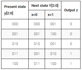
这道题目应该没有什么问题,大家看着状态转移表应该就可以完成。
3.2.5.26 Q3c: FSM logic(Exams/2014 q3c)
module top_module (
    input clk,
    input [2:0] y,
    input x,
    output Y0,
    output z
);

    assign Y0 = (x & y == 3'b000 || ~x & y == 3'b001 || x & y == 3'b010 || ~x & y == 3'b011 || ~x & y == 3'b100);
    assign z = (y == 3'b011 || y == 3'b100);

    /*
    //second way
    parameter S0 = 3'd0, S1 = 3'd1, S2 = 3'd2;
    parameter S3 = 3'd3, S4 = 3'd4;

    reg [2:0]	next_state;

    always@(*)begin
        case(y)
            S0:begin
                next_state = x ? S1 : S0;
            end
            S1:begin
                next_state = x ? S4 : S1;
            end
            S2:begin
                next_state = x ? S1 : S2;
            end
            S3:begin
                next_state = x ? S2 : S1;
            end
            S4:begin
                next_state = x ? S4 : S3;
            end
            default:begin
                next_state = S0;
            end
        endcase
    end

    assign Y0 = (next_state == S1 || next_state == S3);
    assign z = (y == S3 || y == S4);
*/

endmodule
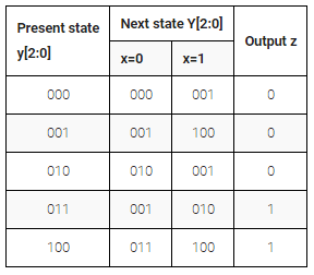
这道题目我没有用到clk,基本上算是为了做题而做题了,两种方法大家看一下吧。
结语
今天更新这几道题目吧,第一道题目需要重点去理解,又是涉及到了状态机和计数器的组合,这种组合在电路设计中用的非常广泛,比如SDRAM控制器,每一个状态之间都需要计数器等待,可以说状态机和计数器是电路设计的精髓了。最后还是那句话,如果哪里有错误,欢迎大家留言~
HDLbits网站链接
https://hdlbits.01xz.net/wiki/Main_Page


