Network-NAT 和 VRRP
NETWORK
- 1 NAT
- 1.1 NAT工作原理
- 1.1.1 NAT
- 1.2 静态转换
- 1.2.1 案例 私网ip访问外网IP
- 1.3 Easy IP
- 1.4 NAT技术
- 2 VRRP
- 2.1 虚拟路由冗余协议
- 2.3 案例: 通过两台三层交换机,一台路由器s3700,连通外网
1 NAT
1.1 NAT工作原理
1.1.1 NAT
- List item
网络地址转换(Network Address Translation)
通过将内部网络的私有IP地址翻译成全球唯一的公网IP地址,使内部网络可以连接到互联网等外部网络上
IPV4 32位 42亿 , IPV6 128位
A 1~127
B 128~191
C 192~223
D 224~239
E 240~254
- 私有地址范围
A 10.0.0.0 ~ 10.255.255.255
B 172.16.0.0 ~ 172.31.255.255
C 192.168.0.0 ~ 192.168.255.255 - NAT实现方式
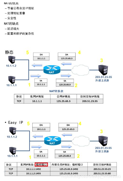
静态转换 一对一 通常用于服务器发布服务到外网
Easy IP 多对一 通常用于仅仅需要访问公网的时候使用,如办公室环境
1.2 静态转换
静态转换是将内部网络的私有地址转换为公有地址时,IP地址的对应关系是确定的
静态转换是一对一的转换 通常用于服务器发布服务到外网
静态转换是双向的
1.2.1 案例 私网ip访问外网IP
- PC1连接外网
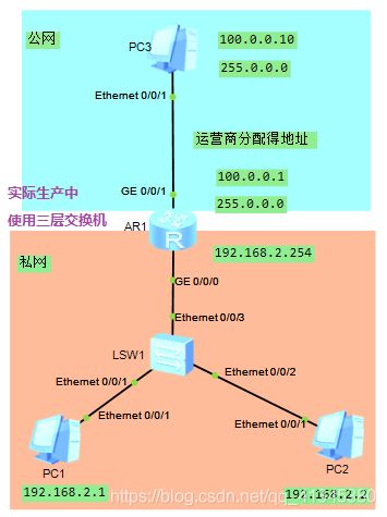
进入外网接口g0/0/1 → nat static global 100.0.0.2 inside 192.168.2.1
(使用Nat的静态转换,将内部的192.168.2.1在与外网互联时转换成公网地址 100.0.0.2)
→ 测试192.168.2.1 ping 外网 100.0.0.10
(192.168.2.1 一出门,将会转换为外网IP 100.0.0.2) - PC2连接外网
进入外网接口g0/0/1 → nat static global 100.0.0.3 inside 192.168.2.2
(使用Nat的静态转换,将内部的192.168.2.2在与外网互联时转换成公网地址 100.0.0.3)
→ 测试192.168.2.2 ping 外网 100.0.0.10
(192.168.2.2 一出门,将会转换为外网IP 100.0.0.3)
注意:需要配置三个运营商公网IP地址
1.3 Easy IP
允许将多个内部网址映射到网关出接口
删除静态转换的IP配置
system-view → in g0/0/1 → display this → undo 复制粘贴对应配置
(undo nat static global 100.0.0.3 inside 192.168.2.2 netmask 255.255.255.255)…
确定可以访问公网的设备
system-view → acl 2000 → rule permit source any
(或rule permit source 192.168.2.0 0.0.0.255)
配置easy ip
in g0/0/1 → nat outbound 2000
[Huawei-GigabitEthernet0/0/1]display this
[V200R003C00]
#
interface GigabitEthernet0/0/1
 ip address 100.0.0.1 255.0.0.0
#
return
[Huawei-GigabitEthernet0/0/1]quit
[Huawei]acl 2000                                //acl
[Huawei-acl-basic-2000]rule permit source any
[Huawei-acl-basic-2000]in g0/0/1
[Huawei-GigabitEthernet0/0/1]nat outbound 2000  //nat outbound  2000
[Huawei-GigabitEthernet0/0/1]display this
[V200R003C00]
#
interface GigabitEthernet0/0/1
 ip address 100.0.0.1 255.0.0.0
 nat outbound 2000
#
return
[Huawei-GigabitEthernet0/0/1]
1.4 NAT技术
2 VRRP
2.1 虚拟路由冗余协议
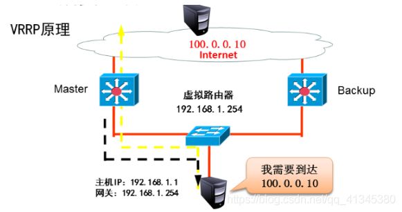
能够在不改变组网的情况下,将多台路由器虚拟成一个虚拟路由器,通过配置虚拟路由器的IP地址为默认网关,实现网关的备份。
2.3 案例: 通过两台三层交换机,一台路由器s3700,连通外网
配基础IP地址,PC1/PC2/三层交换机接口ip配置
三层交换机及路由器,配置动态路由

[sw1]ospf      //设置三层路由sw1的动态路由
[sw1-ospf-1]area 0
[sw1-ospf-1-area-0.0.0.0]network 192.168.1.0 0.0.0.255
[sw1-ospf-1-area-0.0.0.0]network 192.168.2.0 0.0.0.255
//设置sw2的动态路由
[sw2]ospf
[sw2-ospf-1]area 0
[sw2-ospf-1-area-0.0.0.0]network 192.168.1.0 0.0.0.255
[sw2-ospf-1-area-0.0.0.0]network 192.168.3.0 0.0.0.255
//设置AR1的动态路由
[AR1]ospf
[AR1-ospf-1]area 0
[AR1-ospf-1-area-0.0.0.0]network
[AR1-ospf-1-area-0.0.0.0]network 192.168.2.0 0.0.0.255
[AR1-ospf-1-area-0.0.0.0]network 192.168.4.0 0.0.0.255
[AR1-ospf-1-area-0.0.0.0]network 192.168.3.0 0.0.0.255
- VRRP配置
[sw1]in vlan 1
[sw1-Vlanif1]vrrp vrid ?
  INTEGER<1-255>  Virtual router identifier
[sw1-Vlanif1]vrrp vrid 1 virtual-ip 192.168.1.254

/
[sw2]in vlan 1
[sw2-Vlanif1]vrrp vrid 1 virtual-ip 192.168.1.254

///
[sw1-Vlanif1]display vrrp brief      //显示为主vrrp
VRID  State        Interface                Type     Virtual IP
----------------------------------------------------------------
1     Master       Vlanif1                  Normal   192.168.1.254
----------------------------------------------------------------
Total:1     Master:1     Backup:0     Non-active:0

[sw2-Vlanif1]display vrrp brief      //为备份vrrp
VRID  State        Interface                Type     Virtual IP
----------------------------------------------------------------
1     Backup       Vlanif1                  Normal   192.168.1.254
----------------------------------------------------------------
Total:1     Master:0     Backup:1     Non-active:0
测试 pc1 ping pc2
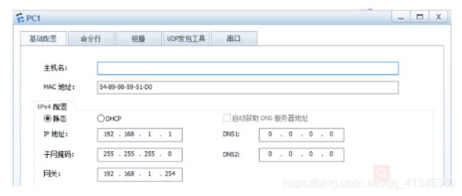
设置网关为虚拟ip 192.168.1.254

将sw1关机后,sw2 变为master, 后几秒中后可以ping通
display vrrp brief
VRID  State        Interface                Type     Virtual IP
----------------------------------------------------------------
1     Master       Vlanif1                  Normal   192.168.1.254
----------------------------------------------------------------
Total:1     Master:1     Backup:0     Non-active:0
优先级设置
指定备份设备(三层交换机)上设置 vrrp vrid 1 priority 105 (优先级默认值为100)
[sw1]in vlanif 1
[sw1-Vlanif1]display vrrp brief
VRID  State        Interface                Type     Virtual IP
----------------------------------------------------------------
1     Backup       Vlanif1                  Normal   192.168.1.254
----------------------------------------------------------------
Total:1     Master:0     Backup:1     Non-active:0

[sw1-Vlanif1]vrrp vrid 1 priority 105
[sw1-Vlanif1]display vrrp brief
VRID  State        Interface                Type     Virtual IP
----------------------------------------------------------------
1     Master       Vlanif1                  Normal   192.168.1.254
----------------------------------------------------------------
Total:1     Master:1     Backup:0     Non-active:0
案例 3 利用上图 ,删除路由器及pc2,实现vlan2的主机也实现vrrp
在s3700交换机创建vlan2,并且将e0/0/4口加入vlan2
[Huawei]vlan 2
[Huawei-vlan2]in e0/0/4
[Huawei-Ethernet0/0/4]port link-type access
[Huawei-Ethernet0/0/4]port default vlan 2
再将其他两个接口设置为trunk
[Huawei]port-group
[Huawei]port-group 1
[Huawei-port-group-1]group-member Ethernet 0/0/1 Ethernet 0/0/2
[Huawei-port-group-1]port link-type trunk
[Huawei-Ethernet0/0/1]port link-type trunk
[Huawei-Ethernet0/0/2]port link-type trunk
[Huawei-port-group-1]port trunk allow-pass vlan all
[Huawei-Ethernet0/0/1]port trunk allow-pass vlan all
[Huawei-Ethernet0/0/2]port trunk allow-pass vlan all
在三层交换机创建vlan2,并配置vlan2的ip,并将连接s3700的接口设置为trunk
[sw1-vlan2]in vlanif 2
[sw1-Vlanif2]ip address 192.168.2.252 24
[sw1-Vlanif2]in g0/0/1
[sw1-GigabitEthernet0/0/1]port link-type trunk
[sw1-GigabitEthernet0/0/1]port trunk allow-pass vlan all
//sw2
[sw2]vlan 2
[sw2-vlan2]in vlanif 2
[sw2-Vlanif2]ip address 192.168.2.253 24
[sw2-Vlanif2]in g0/0/1
[sw2-GigabitEthernet0/0/1]port link-type trunk
[sw2-GigabitEthernet0/0/1]port trunk allow-pass vlan all
VRRP设置,并设置sw2 为master
//进入sw1的vlanif2
[sw1]in vlanif 2
[sw1-Vlanif2]vrrp vrid 2 virtual-ip 192.168.2.254
[sw1-Vlanif2]display vrrp brief


VRID  State        Interface                Type     Virtual IP
----------------------------------------------------------------
1     Master       Vlanif1                  Normal   192.168.1.254
2     Backup       Vlanif2                  Normal   192.168.2.254
----------------------------------------------------------------
Total:2     Master:1     Backup:1     Non-active:0
/
//sw2的vlanif2设置vrrp
[sw2]in vlanif 2
[sw2-Vlanif2]vrrp vrid 2 virtual-ip 192.168.2.254
[sw2-Vlanif2]display vrrp brief
VRID  State        Interface                Type     Virtual IP
----------------------------------------------------------------
1     Backup       Vlanif1                  Normal   192.168.1.254
2     Backup       Vlanif2                  Normal   192.168.2.254
----------------------------------------------------------------
Total:2     Master:0     Backup:2     Non-active:0
[sw2-Vlanif2]vrrp vrid 2 priority 105   //设置sw2的vlanif2 为主
[sw2-Vlanif2]display vrrp brief
[sw2-Vlanif2]display vrrp brief
VRID  State        Interface                Type     Virtual IP
----------------------------------------------------------------
1     Backup       Vlanif1                  Normal   192.168.1.254
2     Master       Vlanif2                  Normal   192.168.2.254
----------------------------------------------------------------
Total:2     Master:1     Backup:1     Non-active:0


