MYIR-ZYNQ7000系列-zturn教程(13):用SPI接口对eeprom M95512进行读写
开发板环境:vivado 2017.1 ,开发板型号xc7z020clg400-1,这个工程是用spi接口对eeprom进行读写
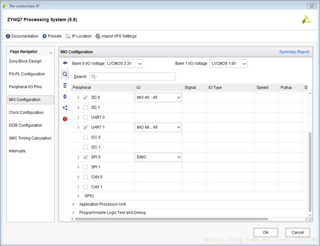
Step1 新建工程然后按照下面截图中进行配置(主要配置了DDR、SD,uart,SPI)
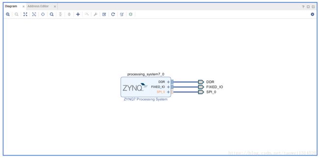
点击自动连线将这些引脚引出如下图所示
Step2 对工程进行综合
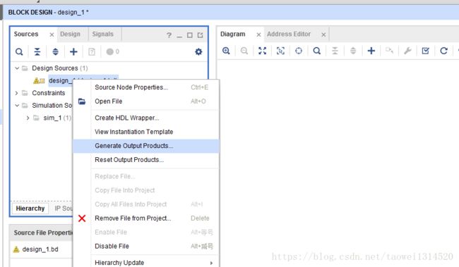
Step3 生成顶层文件
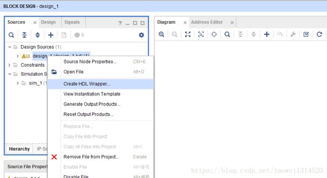
直接生成的顶层有多个IO口,所以我这里更改了顶层文件将用的几个管脚引出了
//Copyright 1986-2017 Xilinx, Inc. All Rights Reserved.
//--------------------------------------------------------------------------------
//Tool Version: Vivado v.2017.1 (win64) Build 1846317 Fri Apr 14 18:55:03 MDT 2017
//Date        : Thu Mar 29 18:40:14 2018
//Host        : taowei running 64-bit Service Pack 1  (build 7601)
//Command     : generate_target design_1_wrapper.bd
//Design      : design_1_wrapper
//Purpose     : IP block netlist
//--------------------------------------------------------------------------------
`timescale 1 ps / 1 ps

module design_1_wrapper
   (DDR_addr,
    DDR_ba,
    DDR_cas_n,
    DDR_ck_n,
    DDR_ck_p,
    DDR_cke,
    DDR_cs_n,
    DDR_dm,
    DDR_dq,
    DDR_dqs_n,
    DDR_dqs_p,
    DDR_odt,
    DDR_ras_n,
    DDR_reset_n,
    DDR_we_n,
    FIXED_IO_ddr_vrn,
    FIXED_IO_ddr_vrp,
    FIXED_IO_mio,
    FIXED_IO_ps_clk,
    FIXED_IO_ps_porb,
    FIXED_IO_ps_srstb,
    spi_0_io0_o,
    spi_0_io1_i,
    spi_0_sck_o,
    spi_0_ss_o
    );
  inout [14:0]DDR_addr;
  inout [2:0]DDR_ba;
  inout DDR_cas_n;
  inout DDR_ck_n;
  inout DDR_ck_p;
  inout DDR_cke;
  inout DDR_cs_n;
  inout [3:0]DDR_dm;
  inout [31:0]DDR_dq;
  inout [3:0]DDR_dqs_n;
  inout [3:0]DDR_dqs_p;
  inout DDR_odt;
  inout DDR_ras_n;
  inout DDR_reset_n;
  inout DDR_we_n;
  inout FIXED_IO_ddr_vrn;
  inout FIXED_IO_ddr_vrp;
  inout [53:0]FIXED_IO_mio;
  inout FIXED_IO_ps_clk;
  inout FIXED_IO_ps_porb;
  inout FIXED_IO_ps_srstb;
  output spi_0_io0_o;
  input spi_0_io1_i;
  output spi_0_sck_o;
  output spi_0_ss_o;

  wire [14:0]DDR_addr;
  wire [2:0]DDR_ba;
  wire DDR_cas_n;
  wire DDR_ck_n;
  wire DDR_ck_p;
  wire DDR_cke;
  wire DDR_cs_n;
  wire [3:0]DDR_dm;
  wire [31:0]DDR_dq;
  wire [3:0]DDR_dqs_n;
  wire [3:0]DDR_dqs_p;
  wire DDR_odt;
  wire DDR_ras_n;
  wire DDR_reset_n;
  wire DDR_we_n;
  wire FCLK_CLK0;
  wire FCLK_CLK1;
  wire FCLK_RESET0_N;
  wire FIXED_IO_ddr_vrn;
  wire FIXED_IO_ddr_vrp;
  wire [53:0]FIXED_IO_mio;
  wire FIXED_IO_ps_clk;
  wire FIXED_IO_ps_porb;
  wire FIXED_IO_ps_srstb;
  wire spi_0_io0_i;
  wire spi_0_io0_io;
  wire spi_0_io0_o;
  wire spi_0_io0_t;
  wire spi_0_io1_i;
  wire spi_0_io1_io;
  wire spi_0_io1_o;
  wire spi_0_io1_t;
  wire spi_0_sck_i;
  wire spi_0_sck_io;
  wire spi_0_sck_o;
  wire spi_0_sck_t;
  wire spi_0_ss1_o;
  wire spi_0_ss2_o;
  wire spi_0_ss_i;
  wire spi_0_ss_io;
  wire spi_0_ss_o;
  wire spi_0_ss_t;

  design_1 design_1_i
       (.DDR_addr(DDR_addr),
        .DDR_ba(DDR_ba),
        .DDR_cas_n(DDR_cas_n),
        .DDR_ck_n(DDR_ck_n),
        .DDR_ck_p(DDR_ck_p),
        .DDR_cke(DDR_cke),
        .DDR_cs_n(DDR_cs_n),
        .DDR_dm(DDR_dm),
        .DDR_dq(DDR_dq),
        .DDR_dqs_n(DDR_dqs_n),
        .DDR_dqs_p(DDR_dqs_p),
        .DDR_odt(DDR_odt),
        .DDR_ras_n(DDR_ras_n),
        .DDR_reset_n(DDR_reset_n),
        .DDR_we_n(DDR_we_n),
        .FIXED_IO_ddr_vrn(FIXED_IO_ddr_vrn),
        .FIXED_IO_ddr_vrp(FIXED_IO_ddr_vrp),
        .FIXED_IO_mio(FIXED_IO_mio),
        .FIXED_IO_ps_clk(FIXED_IO_ps_clk),
        .FIXED_IO_ps_porb(FIXED_IO_ps_porb),
        .FIXED_IO_ps_srstb(FIXED_IO_ps_srstb),
        .SPI_0_io0_i(spi_0_io0_i),
        .SPI_0_io0_o(spi_0_io0_o),
        .SPI_0_io0_t(spi_0_io0_t),
        .SPI_0_io1_i(spi_0_io1_i),
        .SPI_0_io1_o(spi_0_io1_o),
        .SPI_0_io1_t(spi_0_io1_t),
        .SPI_0_sck_i(spi_0_sck_i),
        .SPI_0_sck_o(spi_0_sck_o),
        .SPI_0_sck_t(spi_0_sck_t),
        .SPI_0_ss1_o(spi_0_ss1_o),
        .SPI_0_ss2_o(spi_0_ss2_o),
        .SPI_0_ss_i(spi_0_ss_i),
        .SPI_0_ss_o(spi_0_ss_o),
        .SPI_0_ss_t(spi_0_ss_t));
  IOBUF spi_0_io0_iobuf
       (.I(spi_0_io0_o),
        .IO(spi_0_io0_io),
        .O(spi_0_io0_i),
        .T(spi_0_io0_t));
  IOBUF spi_0_io1_iobuf
       (.I(spi_0_io1_o),
        .IO(spi_0_io1_io),
        .O(spi_0_io1_i),
        .T(spi_0_io1_t));
  IOBUF spi_0_sck_iobuf
       (.I(spi_0_sck_o),
        .IO(spi_0_sck_io),
        .O(spi_0_sck_i),
        .T(spi_0_sck_t));
  IOBUF spi_0_ss_iobuf
       (.I(spi_0_ss_o),
        .IO(spi_0_ss_io),
        .O(spi_0_ss_i),
        .T(spi_0_ss_t));
endmodule
XDC文件如下所示,这个xdc你可以根据自己的开发板设置不同的管脚
set_property PACKAGE_PIN T11 [get_ports spi_0_io1_i]
set_property PACKAGE_PIN T10 [get_ports spi_0_io0_o]
set_property PACKAGE_PIN T12 [get_ports spi_0_sck_o]
set_property PACKAGE_PIN U12 [get_ports spi_0_ss_o]
set_property IOSTANDARD LVCMOS33 [get_ports spi_0_io1_i]
set_property IOSTANDARD LVCMOS33 [get_ports spi_0_io0_o]
set_property IOSTANDARD LVCMOS33 [get_ports spi_0_sck_o]
set_property IOSTANDARD LVCMOS33 [get_ports spi_0_ss_o]
Step4 生成bit文件
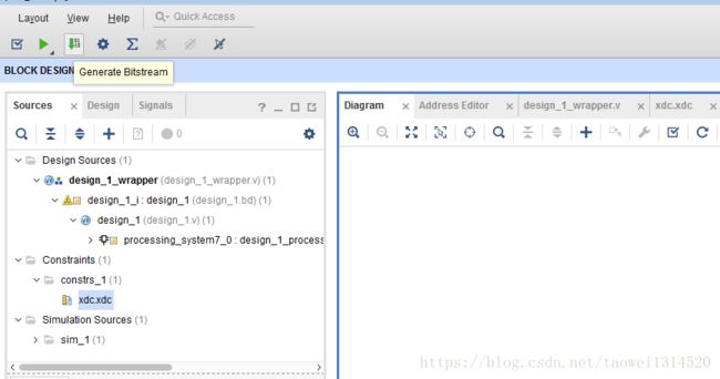
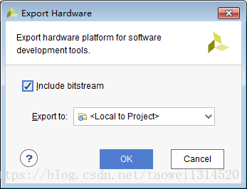
Step5 导出硬件配置
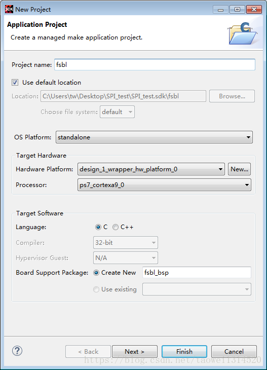
Step6 打开SDK,然后新建一个fsbl
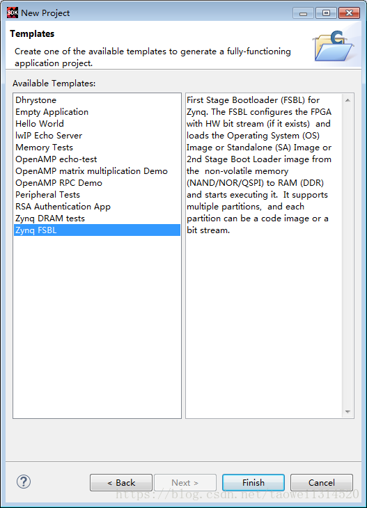
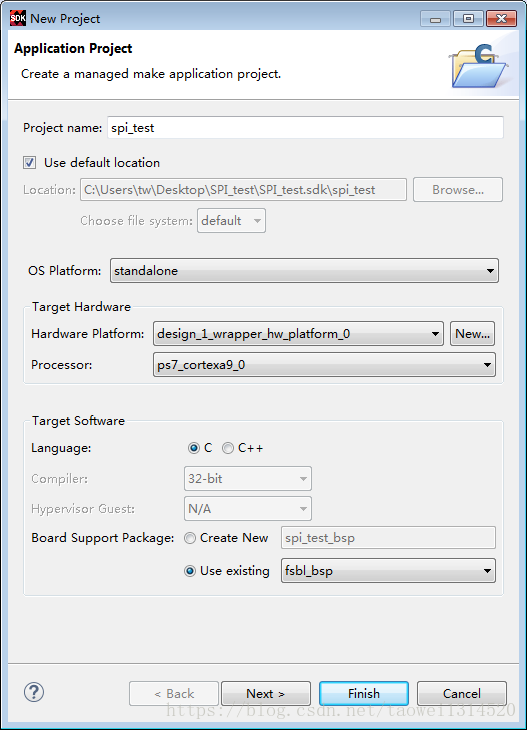
Step7 新建一个spi_test工程
选择一个空的模版

Step8 将xilinx提供的模版工程复制到这个spi_test工程下
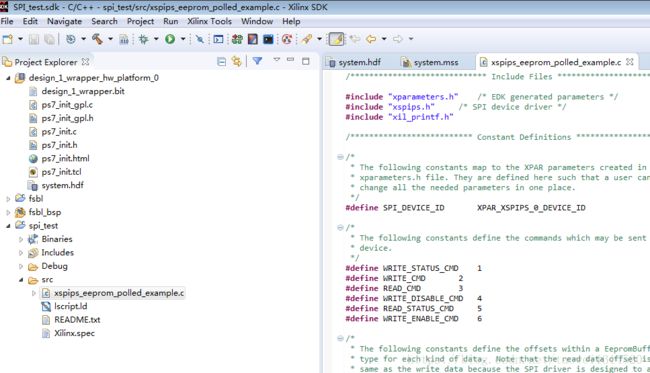
xilinx提供的这个例程基本不需要怎么改就可以用,我这里加了一个写buffer打印和一个读buffer打印并将程
序改了一点,将数据比较给去掉了如果想写其它数据直接改这个写buffer的数据就可以了
/******************************************************************************
*
* Copyright (C) 2010 - 2014 Xilinx, Inc. All rights reserved.
*
* Permission is hereby granted, free of charge, to any person obtaining a copy
* of this software and associated documentation files (the "Software"), to deal
* in the Software without restriction, including without limitation the rights
* to use, copy, modify, merge, publish, distribute, sublicense, and/or sell
* copies of the Software, and to permit persons to whom the Software is
* furnished to do so, subject to the following conditions:
*
* The above copyright notice and this permission notice shall be included in
* all copies or substantial portions of the Software.
*
* Use of the Software is limited solely to applications:
* (a) running on a Xilinx device, or
* (b) that interact with a Xilinx device through a bus or interconnect.
*
* THE SOFTWARE IS PROVIDED "AS IS", WITHOUT WARRANTY OF ANY KIND, EXPRESS OR
* IMPLIED, INCLUDING BUT NOT LIMITED TO THE WARRANTIES OF MERCHANTABILITY,
* FITNESS FOR A PARTICULAR PURPOSE AND NONINFRINGEMENT. IN NO EVENT SHALL
* XILINX BE LIABLE FOR ANY CLAIM, DAMAGES OR OTHER LIABILITY,
* WHETHER IN AN ACTION OF CONTRACT, TORT OR OTHERWISE, ARISING FROM, OUT OF
* OR IN CONNECTION WITH THE SOFTWARE OR THE USE OR OTHER DEALINGS IN THE
* SOFTWARE.
*
* Except as contained in this notice, the name of the Xilinx shall not be used
* in advertising or otherwise to promote the sale, use or other dealings in
* this Software without prior written authorization from Xilinx.
*
******************************************************************************/
/*****************************************************************************/
/**
* @file xspi_eeprom_polled_example.c
**
* This file contains a design example using the SPI driver (XSpiPs) in
* polled mode and hardware device with a serial EEPROM device. The
* hardware which this example runs on must have a serial EEPROM (Microchip
* 25XX320 or 25XX160) for it to run. This example has been tested with the
* SPI EEPROM on the EP4.5 ARM processor.
*
* @note
*
* None.
*
*
* MODIFICATION HISTORY:
*
* Ver Who Date Changes
* ----- ---- -------- -----------------------------------------------
* 1.00 sdm 03/09/10 First release
* 1.00 sdm 10/25/11 Updated the chip select to be used to second chip select
*
*
*
******************************************************************************/
/***************************** Include Files *********************************/
#include "xparameters.h" /* EDK generated parameters */
#include "xspips.h" /* SPI device driver */
#include "xil_printf.h"
/************************** Constant Definitions *****************************/
/*
* The following constants map to the XPAR parameters created in the
* xparameters.h file. They are defined here such that a user can easily
* change all the needed parameters in one place.
*/
#define SPI_DEVICE_ID XPAR_XSPIPS_0_DEVICE_ID
/*
* The following constants define the commands which may be sent to the EEPROM
* device.
*/
#define WRITE_STATUS_CMD 1
#define WRITE_CMD 2
#define READ_CMD 3
#define WRITE_DISABLE_CMD 4
#define READ_STATUS_CMD 5
#define WRITE_ENABLE_CMD 6
/*
* The following constants define the offsets within a EepromBuffer data
* type for each kind of data. Note that the read data offset is not the
* same as the write data because the SPI driver is designed to allow full
* duplex transfers such that the number of bytes received is the number
* sent and received.
*/
#define COMMAND_OFFSET 0 /* EEPROM instruction */
#define ADDRESS_MSB_OFFSET 1 /* MSB of address to read or write */
#define ADDRESS_LSB_OFFSET 2 /* LSB of address to read or write */
#define DATA_OFFSET 3
#define WRITE_DATA_OFFSET 3 /* Start of data to write to the EEPROM */
#define READ_DATA_OFFSET 6 /* Start of data read from the EEPROM */
/*
* The following constants specify the extra bytes which are sent to the
* EEPROM on the SPI interface, that are not data, but control information
* which includes the command and address
*/
#define OVERHEAD_SIZE 3
/*
* The following constants specify the page size and number of pages for the
* EEPROM. The page size specifies a max number of bytes that can be written
* to the EEPROM with a single transfer using the SPI driver.
*/
#define PAGE_SIZE 16
#define PAGE_COUNT 1
/*
* The following constants specify the max amount of data and the size of the
* the buffer required to hold the data and overhead to transfer the data to
* and from the EEPROM.
*/
#define MAX_DATA PAGE_COUNT * PAGE_SIZE
#define BUFFER_SIZE MAX_DATA + READ_DATA_OFFSET
/*
* The following constant defines the slave select signal that is used to
* to select the EEPROM device on the SPI bus, this signal is typically
* connected to the chip select of the device
*/
#define EEPROM_SPI_SELECT 0x00
/**************************** Type Definitions *******************************/
/*
* The following data type is used to send and receive data to the serial
* EEPROM device connected to the SPI interface. It is an array of bytes
* rather than a structure for portability avoiding packing issues. The
* application must setup the data to be written in this buffer and retrieve
* the data read from it.
*/
typedef u8 EepromBuffer[BUFFER_SIZE];
/***************** Macros (Inline Functions) Definitions *********************/
/************************** Function Prototypes ******************************/
void EepromRead(XSpiPs *SpiPtr, u16 Address, int ByteCount,
EepromBuffer Buffer);
void EepromWrite(XSpiPs *SpiPtr, u16 Address, u8 ByteCount,
EepromBuffer Buffer);
int SpiPsEepromPolledExample(XSpiPs *SpiInstancePtr, u16 SpiDeviceId);
/************************** Variable Definitions *****************************/
/*
* The instances to support the device drivers are global such that the
* are initialized to zero each time the program runs. They could be local
* but should at least be static so they are zeroed.
*/
static XSpiPs SpiInstance;
/*
* The following variable allows a test value to be added to the values that
* are written to the EEPROM such that unique values can be generated to
* guarantee the writes to the EEPROM were successful
*/
int Test;
/*
* The following variables are used to read and write to the eeprom and they
* are global to avoid having large buffers on the stack
*/
EepromBuffer ReadBuffer;
EepromBuffer WriteBuffer;
/*****************************************************************************/
/**
*
* Main function to call the Spi Eeprom example.
*
* @param None
*
* @return XST_SUCCESS if successful, otherwise XST_FAILURE.
*
* @note None
*
******************************************************************************/
int main(void)
{
int Status;
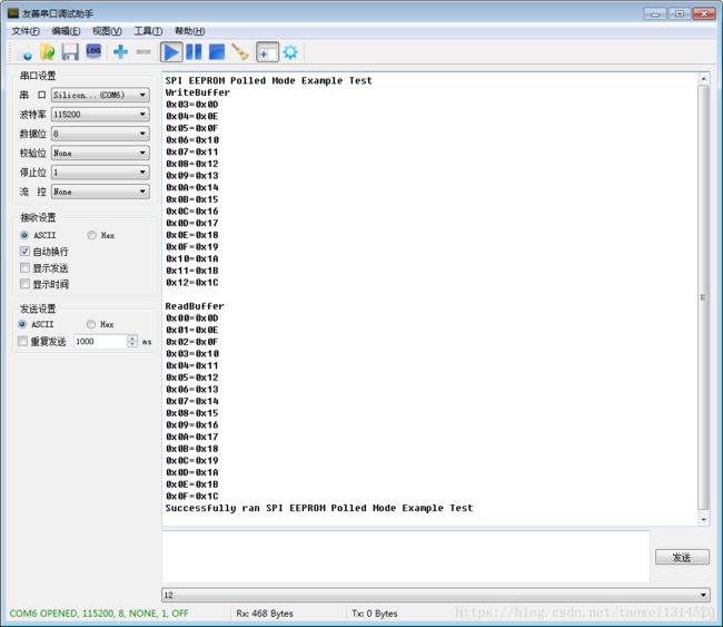
xil_printf("SPI EEPROM Polled Mode Example Test \r\n");
/*
* Run the Spi Interrupt example.
*/
Status = SpiPsEepromPolledExample(&SpiInstance, SPI_DEVICE_ID);
if (Status != XST_SUCCESS) {
xil_printf("SPI EEPROM Polled Mode Example Test Failed\r\n");
return XST_FAILURE;
}
xil_printf("Successfully ran SPI EEPROM Polled Mode Example Test\r\n");
return XST_SUCCESS;
}
/*****************************************************************************
*
* The purpose of this function is to illustrate how to use the XSpiPs
* device driver in polled mode. This test writes and reads data from a
* serial EEPROM. The serial EEPROM part must be present in the hardware
* to use this example.
*
* @param SpiInstancePtr is a pointer to the Spi Instance.
* @param SpiDeviceId is the Device Id of Spi.
*
* @return XST_SUCCESS if successful else XST_FAILURE.
*
* @note
*
* This function calls functions which contain loops that may be infinite
* if interrupts are not working such that it may not return. If the device
* slave select is not correct and the device is not responding on bus it will
* read a status of 0xFF for the status register as the bus is pulled up.
*
*****************************************************************************/
int SpiPsEepromPolledExample(XSpiPs *SpiInstancePtr, u16 SpiDeviceId)
{
int Status;
u8 *BufferPtr;
u8 UniqueValue;
int Count;
int Page;
int i;
XSpiPs_Config *SpiConfig;
/*
* Initialize the SPI driver so that it's ready to use
*/
SpiConfig = XSpiPs_LookupConfig(SpiDeviceId);
if (NULL == SpiConfig) {
return XST_FAILURE;
}
Status = XSpiPs_CfgInitialize(SpiInstancePtr, SpiConfig,
SpiConfig->BaseAddress);
if (Status != XST_SUCCESS) {
return XST_FAILURE;
}
/*
* Perform a self-test to check hardware build
*/
Status = XSpiPs_SelfTest(SpiInstancePtr);
if (Status != XST_SUCCESS) {
return XST_FAILURE;
}
/*
* Set the Spi device as a master. External loopback is required.
*/
XSpiPs_SetOptions(SpiInstancePtr, XSPIPS_MASTER_OPTION |
XSPIPS_FORCE_SSELECT_OPTION);
XSpiPs_SetClkPrescaler(SpiInstancePtr, XSPIPS_CLK_PRESCALE_128);
/*
* Initialize the write buffer for a pattern to write to the EEPROM
* and the read buffer to zero so it can be verified after the read, the
* test value that is added to the unique value allows the value to be
* changed in a debug environment to guarantee
*/
for (UniqueValue = 13, Count = 0; Count < MAX_DATA;
Count++, UniqueValue++) {
WriteBuffer[WRITE_DATA_OFFSET + Count] =
(u8)(UniqueValue + Test);
ReadBuffer[READ_DATA_OFFSET + Count] = 0xA5;
}
xil_printf("WriteBuffer\n");
for(i=0;i> 8);
Buffer[ADDRESS_LSB_OFFSET] = (u8)(Address & 0x00FF);
/*
* Send the read command to the EEPROM to read the specified number
* of bytes from the EEPROM, send the read command and address and
* receive the specified number of bytes of data in the data buffer
*/
XSpiPs_PolledTransfer(SpiPtr, Buffer, &Buffer[DATA_OFFSET],
ByteCount + OVERHEAD_SIZE);
}
/******************************************************************************
*
*
* This function writes to the serial EEPROM connected to the SPI interface.
* This function is not designed to be a driver to handle all
* the conditions of the EEPROM device. The EEPROM contains a 32 byte write
* buffer which can be filled and then a write is automatically performed by
* the device. All the data put into the buffer must be in the same page of
* the device with page boundaries being on 32 byte boundaries.
*
* @param SpiPtr is a pointer to the SPI driver instance to use.
* @param Address contains the address to write data to in the EEPROM.
* @param ByteCount contains the number of bytes to write.
* @param Buffer is a buffer of data to write from.
*
* @return None.
*
* @note None.
*
******************************************************************************/
void EepromWrite(XSpiPs *SpiPtr, u16 Address, u8 ByteCount,
EepromBuffer Buffer)
{
u8 WriteEnableCmd = { WRITE_ENABLE_CMD };
u8 ReadStatusCmd[] = { READ_STATUS_CMD, 0 }; /* must send 2 bytes */
u8 EepromStatus[2];
int DelayCount = 0;
/*
* Send the write enable command to the SEEPOM so that it can be
* written to, this needs to be sent as a seperate transfer before
* the write
*/
XSpiPs_PolledTransfer(SpiPtr, &WriteEnableCmd, NULL,
sizeof(WriteEnableCmd));
/*
* Setup the write command with the specified address and data for the
* EEPROM
*/
Buffer[COMMAND_OFFSET] = WRITE_CMD;
Buffer[ADDRESS_MSB_OFFSET] = (u8)((Address & 0xFF00) >> 8);
Buffer[ADDRESS_LSB_OFFSET] = (u8)(Address & 0x00FF);
/*
* Send the write command, address, and data to the EEPROM to be
* written, no receive buffer is specified since there is nothing to
* receive
*/
XSpiPs_PolledTransfer(SpiPtr, Buffer, NULL, ByteCount + OVERHEAD_SIZE);
/*
* Wait for a bit of time to allow the programming to occur as reading
* the status while programming causes it to fail because of noisy power
* on the board containing the EEPROM, this loop does not need to be
* very long but is longer to hopefully work for a faster processor
*/
while (DelayCount++ < 10000) {
}
/*
* Wait for the write command to the EEPROM to be completed, it takes
* some time for the data to be written
*/
while (1) {
/*
* Poll the status register of the device to determine when it
* completes by sending a read status command and receiving the
* status byte
*/
XSpiPs_PolledTransfer(SpiPtr, ReadStatusCmd, EepromStatus,
sizeof(ReadStatusCmd));
/*
* If the status indicates the write is done, then stop waiting,
* if a value of 0xFF in the status byte is read from the
* device and this loop never exits, the device slave select is
* possibly incorrect such that the device status is not being
* read
*/
if ((EepromStatus[1] & 0x03) == 0) {
break;
}
}
}
这个工程注意的地方:
#define EEPROM_SPI_SELECT 0x00这个宏定义是选择那个片选这里设置的是ss0这个管脚,根据手册可以看出一共可以引出三个ss片选
而且我这里的工程顶层也只是引出了ss0这个片选管脚

XSpiPs_SetClkPrescaler(SpiInstancePtr, XSPIPS_CLK_PRESCALE_128);
这个宏定义是设置spi的速率的,可以根据手册进行设置
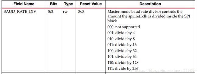
而且这里mio和emio的时钟是不一样,手册里面也提到了,mio时sclk为50M,emio时sclk为25M
• 50 MHz SCLK clock frequency when I/O signals are routed to the MIO pins
° 25 MHz SCLK when the I/O signals are routed via the EMIO interface to the PL pins
#define SPI_DEVICE_ID XPAR_XSPIPS_0_DEVICE_ID这个宏定义主要看你用的是spi0还是spi1不同的设备有不同的地址我这里选择的是spi0自己做工程时可以注意下
下面这个是开发板的连接,因这个M95512 的spi eeprom芯片没有做好的模块只有芯片卖,所以自己买了一个
芯片和一个线路板焊接的,不过这里主要是实现spi的读写已经达到预期的目标。
从串口调试助手中可以看出写入的和读出的是一样的