Xilinx-Verilog-学习笔记(14):Verilog基础语法演示(1)
Xilinx-Verilog-学习笔记(14):Verilog基础语法演示(1)
一、module、always、wire、reg型变量使用
1、触发器
1.1 design文件
//此处为模块与接口定义
module ex_trigger(
	input wire			sclk,
	input wire			rst_n,
	input wire	[7:0]	d,
	output wire	[7:0]	q
);
//声明一个寄存器型用于always中
reg		[7:0]	q_r;
//always块
always @(posedge sclk or negedge rst_n)
	if(rst_n == 1'b0)
		q_r <= 8'h00;
	else
		q_r <= d;

assign	q = q_r;

endmodule
注意事项:
(1)模块声明的时候,输入必须是wire 变量,输出可以是 wire 变量也可以是 reg。在always块内被赋值的每一个信号都必须定义成reg型。
wire型变量通常用来表示用以assign关键字指定的组合逻辑信号。reg型数据常用来表示always块内的指定信号,常代表触发器。
(2)wire型生成的RTL其实就是一根线,reg型生成的RTL其实是一个D触发器。
(3)敏感列表可以包括电平触发或者沿触发。
(4)沿触发的逻辑里边一定要用<=非阻塞赋值。
(5)wire变量一定用assign连续赋值语句赋值,而且必须用阻塞赋值。
(6)赋值时:二进制整数(b或B)、十进制整数(d或D)、十六进制整数(h或H)、八进制(o或O)。 如上述代码:8’h00其中8表示占用bit位数,h表示基数,00表示值。
1.2 testbench文件
`timescale 1ns/1ns

module tb_ex_trigger;
	reg tb_sclk,tb_rst_n;
	reg		[7:0]	tb_d;
	wire	[7:0]	tb_q;

	initial
	begin
		tb_sclk <= 0;
		tb_rst_n <= 0;
		#50
		tb_d <= 1;
		#50
		tb_rst_n <= 1;
	end


always #10 tb_sclk <= ~tb_sclk;

ex_trigger ex_trigger_inst(
	.sclk		(tb_sclk),
	.rst_n		(tb_rst_n),
	.d			(tb_d),
	.q			(tb_q)
);

endmodule
注意事项:
(1)timescale是用来限制时间精度的。
(2)initial语句上电只执行一次。
(3)实例化过程中,.内部端口 (外部端口)。
(4)例化模块的时候如果原始模块是输出信号,那么括号内必须是wire变量。
(5)寄存器reg的赋值方法是:时钟低电平时将数据加载到寄存器d端,当上升沿来临时把d端的数据打到q端。
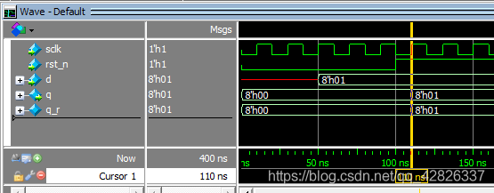
1.3 仿真波形

解析:从波形可以看出,当50ns时,d信号被置为1,当100ns时,rst_n信号被拉高,在下一个时钟上升沿到来时,q被赋予了d的值。
注意事项:
在数字电路中,x代表不定值,z代表高阻值。
2、计数器
2.1 design文件
module	ex_cnt(
	input	wire			sclk,
	input	wire			rst_n,
	output	wire	[3:0]	cnt
);


reg		[3:0]	cnt_r;

always @(posedge sclk or negedge rst_n)
	if(rst_n == 1'b0)
		cnt_r <= 4'd0;
	else
		cnt_r <= cnt_r + 1'b1;

assign cnt = cnt_r;


endmodule
2.2 testbench文件
`timescale 1ns/1ns

module	tb_ex_cnt;
	reg		tb_sclk,tb_rst_n;
	wire	[3:0]	tb_cnt;

	initial
	begin
		tb_sclk <= 0;
		tb_rst_n <= 0;
		#100
		tb_rst_n <= 1;
	end

always #10 tb_sclk <= ~tb_sclk;

ex_cnt	ex_cnt_inst(
	.sclk		(tb_sclk),
	.rst_n		(tb_rst_n),
	.cnt		(tb_cnt)
);

endmodule
2.3 仿真波形

解析:从波形可以看出,当100ns时,rst_n信号被拉高,在下一个时钟上升沿到来时,计数器开始加1,由于定义计数器变量时位宽定义为4,所以最大可记的值为15,再加1则重新回到0。
二、case、task语句使用
1、case跳转小练习
1.1 design文件
module ex_case(
	input	wire	sclk,
	input	wire	rst_n,
	output	reg		[7:0]	o_data,
	input	wire	[9:0]	i_data,
	input	wire	[7:0]	i_addr
);

reg		[2:0]	cnt_7;

always @(posedge sclk or negedge rst_n)
	if(rst_n == 1'b0)
		cnt_7 <= 3'd0;
	else
		cnt_7 <= cnt_7 + 1'b1;

always @(posedge sclk or negedge rst_n)
	if(rst_n == 1'b0)
		begin
			o_data <= 8'd0;
		end
	else
		begin
			case(cnt_7)
				3'd0:begin
						o_data <= 3'd7;
					 end
				3'd1:begin
						o_data <= 3'd0;
					 end
				3'd2:begin
						o_data <= 3'd5;
					 end
				default:begin
						o_data <= 3'd0;
					 end
			endcase
		end

endmodule
1.2 testbench文件
`timescale 1ns/1ns

module	tb_ex_case;
	reg		tb_sclk,tb_rst_n;
	reg		[9:0]	i_data;
	reg		[7:0]	i_addr;
	wire	[7:0]	o_data;

initial
	begin
		tb_sclk <= 0;
		tb_rst_n <= 0;
		#100
		tb_rst_n <= 1;
	end

initial
	begin
		i_data <= 0;
		i_addr <= 0;
		#200
		send_data(255);	//task的执行
	end

always #10 tb_sclk <= ~tb_sclk;

ex_case		ex_case_inst(
	.sclk				(tb_sclk),
	.rst_n				(tb_rst_n),
	.o_data				(o_data),
	.i_data				(i_data),
	.i_addr				(i_addr)
);

//任务的声明
task send_data(len);
	integer i;
	begin
		for(i=0;i;i=i+1)
			begin
				//按时钟节拍来
				@(posedge tb_sclk)
				i_addr<=i;
				i_data<=i;
/* 				case(i_addr)
					3'd0:begin
							i_data <= 8'h0xff;
						 end
					3'd1:begin
							i_data <= 8'h0x55;
						 end
					3'd2:begin
							i_data <= 8'h0x00;
						 end
					default:begin
							i_data <= 8'h0xff;
						 end
				endcase
*/
			end
				i_addr <= 0;
				i_data <= 0;
	end
endtask

endmodule
解析:首先是design文件中,随着cnt的数值加1,最多是3位宽所以数值范围为0~7,当cnt为0时,下一个时钟沿到来时o_data置7,其余同理(见左1线)。在testbench中,通过task实现for循环加1,for循环中i的值在每次时钟上升沿到来时赋给i_addr,当i_addr为0时,下一个时钟上升沿到来时i_data被赋为0xff,其余同理(见左2线)。
注意事项:
(1)不同功能的寄存器分开always块来写,使代码可读性强。
(2)对多条语句进行赋值时候要用begin end。
(3)case在电路中就相当于一个编解码器,在FPGA内是用LUT实现的,把输入数据输进去然后查表得到结果·。
(4)消除锁存器的方式:敏感列表写全,case条件,赋值语句的右边变量;所有条件分支写全。
(5)在task中,如果想使的代码按照时钟节拍走,则需要加 @(posedge sclk),其实该语句也是按顺序进行,只不过延时时间为0ns非常快。
2、同步有限状态机FSM
有限状态机是有寄存器组和组合逻辑构成的硬件时序电路。其状态的转换不但取决于各个输入值,还取决于当前状态。
下面用两段式实现:

2.1 design文件
module ex_fsm(
	input	wire	sclk,
	input	wire	rst_n,
	input	wire	A,
	output	reg		K1,
	output	reg		K2
);

parameter		IDLE 	= 4'b0001;
parameter		START	= 4'b0010;
parameter		STOP 	= 4'b0100;
parameter		CLEAR	= 4'b1000;

reg		[3:0]	state;

//第一段:描述状态变化
always @(posedge sclk or negedge rst_n)
	if(rst_n == 1'b0)
		state <= IDLE;
	else
		case(state)
			IDLE: if(A == 1'b1)
				state <= START;
			START: if(A == 1'b0)
				state <= STOP;
			STOP: if(A == 1'b1)
				state <= CLEAR;
			CLEAR:if(A == 1'b0)
				state <= IDLE;
			default:state <= IDLE;
		endcase

//第二段:描述输出过程
always @(posedge sclk or negedge rst_n)
	if(rst_n == 1'b0)
		K1 <= 1'b0;
	else if(state == IDLE && A == 1'b1)
		K1 <= 1'b0;
	else if(state == CLEAR && A == 1'b0)
		K1 <= 1'b1;

always @(posedge sclk or negedge rst_n)
	if(rst_n == 1'b0)
		K2 <= 1'b0;
	else if(state == STOP && A == 1'b1)
		K2 <= 1'b1;
	else if(state == CLEAR && A == 1'b0)
		K2 <= 1'b0;

endmodule
注意事项:
(1)二进制编码用的寄存器数量少,但是用的组合逻辑资源比较多。
2’b00 2’b01 2’b10 2’b11
(2)独热码用的寄存器数量多,但是用的组合逻辑资源比较少。
4’b0001 4’b0010 4’b0100 4’b1000
if(state == 4’b0001)会被优化成if(state[0] == 1’b1)
(3)parameter用来定义某个变量的,一般用作状态机中,有点类似于C语言的宏定义。
(4)两段式:第一段描述状态机的状态处理(时序逻辑);第二段描述状态机的输出(k1和k2最好分开写)。
2.2 testbench文件
`timescale 1ns/1ns

module	tb_ex_fsm;
	reg		tb_sclk,tb_rst_n;
	reg		in_A;
	wire	K1;
	wire	K2;

initial
	begin
		tb_sclk <= 0;
		tb_rst_n <= 0;
		#100
		tb_rst_n <= 1;
	end

initial
	begin
		#200
		in_data();
	end

always #10 tb_sclk <= ~tb_sclk;

ex_fsm	ex_fsm_inst(
	.sclk		(tb_sclk),
	.rst_n		(tb_rst_n),
	.A			(in_A),
	.K1			(K1),
	.K2			(K2)
);

task in_data();
	integer i;
	begin
		for(i=0;i<512;i=i+1)
			begin
				@(posedge tb_sclk);
				if(i<50)
					in_A <= 0;
				else if(i<150)
					in_A <= 1;
				else if(i<250)
					in_A <= 0;
				else if(i<350)
					in_A <= 1;
				else if(i<450)
					in_A <= 0;
			end
	end
endtask

endmodule
2.3 仿真波形

解析:首先看状态机切换,IDLE状态下A拉高->START状态,START状态下A拉低->STOP状态,STOP状态下A拉高->CLEAR状态,CLEAR状态下A拉低->IDLE状态。再看输出状态,STOP状态下A拉高->K2置1,CLEAR状态下A拉低->K1置1。
