视觉SLAM入门 -- 学习笔记 - Part5

2 ORB 特征点

原图见1.png 文件和2.png。

2.1 ORB 提取

ORB 即Oriented FAST 简称。它实际上是FAST 特征再加上一个旋转量。本习题将使用OpenCV 自带的FAST 提取算法,但是你要完成旋转部分的计算。旋转的计算过程描述如下:
在一个小图像块中,先计算质心。质心是指以图像块灰度值作为权重的中心。

  1. 在一个小的图像块B 中,定义图像块的矩为:
    视觉SLAM入门 -- 学习笔记 - Part5_第1张图片

  2. 通过矩可以找到图像块的质心:
    在这里插入图片描述

  3. 连接图像块的几何中心O 与质心C,得到一个方向向量 O C ⃗ \vec{OC} OC ,于是特征点的方向可以定义为:
    在这里插入图片描述
    实际上只需计算 m 01 m_{01} m01 m 10 m_{10} m10 即可。习题中取图像块大小为16x16,即对于任意点(u, v),图像块从(u - 8, v - 8) 取到(u + 7, v + 7) 即可。请在习题的computeAngle 中,为所有特征点计算这个旋转角。

提示:

  1. 由于要取图像16x16 块,所以位于边缘处的点(比如u < 8 的)对应的图像块可能会出界,此时 需要判断该点是否在边缘处,并跳过这些点。
  2. 由于矩的定义方式,在画图特征点之后,角度看起来总是指向图像中更亮的地方。
  3. std::atan 和std::atan2 会返回弧度制的旋转角,但OpenCV 中使用角度制,如使用std::atan 类函数,请转换一下。

作为验证,第一个图像的特征点如图1 所示。看不清可以放大看。

图1: 带有旋转的FAST
视觉SLAM入门 -- 学习笔记 - Part5_第2张图片

computeAngle()

/**
 * compute the angle for ORB descriptor
 * @param [in] image input image
 * @param [in|out] detected keypoints
 */
#define Rad_to_deg  45.0 / atan(1.0)
void computeAngle(const cv::Mat &img, vector<cv::KeyPoint> &keypoints) {
     
    int half_patch_size = 8;
    for (auto &kp : keypoints) {
     
        // START YOUR CODE HERE (~7 lines)


        if (kp.pt.x < half_patch_size || kp.pt.y < half_patch_size ||
            kp.pt.x >= img.cols - half_patch_size || kp.pt.y >= img.rows - half_patch_size) {
     
            
            //outside
//            bad_points++;
//            descriptors.push_back({});
            continue;
        }

        float m01 = 0, m10 = 0;
        for (int dx = -half_patch_size; dx < half_patch_size; ++dx) {
     
            for (int dy = -half_patch_size; dy < half_patch_size; ++dy) {
     
                uchar pixel = img.at<uchar>(kp.pt.y + dy, kp.pt.x + dx);
                m10 += dx * pixel;
                m01 += dy * pixel;
            }
        }

        // angle should be arc tan(m01/m10);
        kp.angle = atan(m01 / m10) * Rad_to_deg; // compute kp.angle
//        float m_sqrt = sqrt(m01 * m01 + m10 * m10) + 1e-08; // avoid divide by zero
//        float sin_theta = m01/m_sqrt;
//        float cos_theta = m10/m_sqrt;

        // END YOUR CODE HERE
    }
//    return;
}

2.2 ORB 描述

ORB 描述即带旋转的BRIEF 描述。所谓BRIEF 描述是指一个0-1 组成的字符串(可以取256 位或128 位),每一个bit 表示一次像素间的比较。算法流程如下:

  1. 给定图像I 和关键点(u,v),以及该点的转角 θ \theta θ。以256 位描述为例,那么最终描述子

在这里插入图片描述
2. 对任意i = 1, … , 256, d i d_{i} di 的计算如下。取(u, v) 附近任意两个点p, q,并按照 θ \theta θ 进行旋转:

在这里插入图片描述

推导可参考:
视觉SLAM入门 -- 学习笔记 - Part5_第3张图片
https://www.cnblogs.com/meteoric_cry/p/7987548.html

其中 u p u_{p} up, v p v_{p} vp 为p 的坐标,对q 亦然。记旋转后的p, q 为p′, q′,那么比较I(p′) 和I(q′),若前者大,记 d i d_{i} di = 0,反之记 d i d_{i} di = 1。(注意反过来记也可以,但是程序中要保持一致。)

这样我们就得到了ORB 的描述。我们在程序中用256 个bool 变量表达这个描述。(严格来说可以用32 个uchar 以节省空间,但是那样涉及到位运算,本习题只要求掌握算法)
请你完成compute-ORBDesc 函数,实现此处计算。注意,通常我们会固定p, q 的取法(称为ORB 的pattern),否则每次都重新随机选取,会使得描述不稳定。我们在全局变量ORB_pattern 中定义了p, q 的取法,格式为 u p u_{p} up, v p v_{p} vp, u q u_{q} uq, v q v_{q} vq。请你根据给定的pattern 完成ORB 描述的计算。

提示:

  1. p, q 同样要做边界检查,否则会跑出图像外。如果跑出图像外,就设这个描述子为空。
  2. 调用cos 和sin 时同样请注意弧度和角度的转换。

computeORBDesc()

/**
 * compute ORB descriptor
 * @param [in] image the input image
 * @param [in] keypoints detected keypoints
 * @param [out] desc descriptor
 */
typedef vector<bool> DescType;  // type of descriptor, 256 bools
void computeORBDesc(const cv::Mat &image, vector<cv::KeyPoint> &keypoints, vector<DescType> &desc) {
     
    for (auto &kp: keypoints) {
     
        DescType d(256, false);
        for (int i = 0; i < 256; i++) {
     
            // START YOUR CODE HERE (~7 lines)

            if (kp.pt.x < 16 || kp.pt.y < 16 ||
                kp.pt.x >= image.cols - 16 || kp.pt.y >= image.rows - 16) {
     
//                d[i] = 0;  // if kp goes outside, set d.clear()
                d.clear();
                break;
            }

            cv::Point2f p(ORB_pattern[i*4], ORB_pattern[i*4 + 1]);
            cv::Point2f q(ORB_pattern[i*4 + 2], ORB_pattern[i*4 + 3]);

            cv::Point2f pp = cv::Point2f(cos(kp.angle/180)*p.x - sin(kp.angle/180)*p.y,
                           sin(kp.angle/180)*p.x + cos(kp.angle/180)*p.y) + kp.pt;
            cv::Point2f qq = cv::Point2f(cos(kp.angle/180)*q.x - sin(kp.angle/180)*q.y,
                           sin(kp.angle/180)*q.x + cos(kp.angle/180)*q.y) + kp.pt;

            if(image.at<uchar>(pp.y, pp.x) < image.at<uchar>(qq.y, qq.x)){
     
                d[i] = true;
            }

            // END YOUR CODE HERE
        }
        desc.push_back(d);
    }

    int bad = 0;
    for (auto &d: desc) {
     
        if (d.empty()) bad++;
    }
    cout << "bad/total: " << bad << "/" << desc.size() << endl;
//    return;
}

代码输出:
视觉SLAM入门 -- 学习笔记 - Part5_第4张图片

2.3 暴力匹配

在提取描述之后,我们需要根据描述子进行匹配。暴力匹配是一种简单粗暴的匹配方法,在特征点不多时很有用。下面你将根据习题指导,书写暴力匹配算法。
所谓暴力匹配思路很简单。给定两组描述子P = [ p 1 p_{1} p1,…, p M p_{M} pM] 和Q = [ p 1 p_{1} p1,…, p N p_{N} pN]。那么,对P 中任意一个点,找到Q 中对应最小距离点,即算一次匹配。但是这样做会对每个特征点都找到一个匹配,所以我们通常还会限制一个距离阈值 d m a x d_{max} dmax,即认作匹配的特征点距离不应该大于 d m a x d_{max} dmax。下面请你根据上述描述,实现函数bfMatch,返回给定特征点的匹配情况。实践中取 d m a x d_{max} dmax = 50。

提示:

  1. 你需要按位计算两个描述子之间的汉明距离。
  2. OpenCV 的DMatch 结构,queryIdx 为第一图的特征ID,trainIdx 为第二个图的特征ID。
  3. 作为验证,匹配之后输出图像应如图2 所示。
    图2: 匹配图像

bfMatch()

/**
 * brute-force match two sets of descriptors
 * @param desc1 the first descriptor
 * @param desc2 the second descriptor
 * @param matches matches of two images
 */
void bfMatch(const vector<DescType> &desc1, const vector<DescType> &desc2, vector<cv::DMatch> &matches) {
     
    int d_max = 50;

    // START YOUR CODE HERE (~12 lines)
    // find matches between desc1 and desc2.
    for (int i1 = 0; i1 < desc1.size(); ++i1) {
     
        if(desc1[i1].empty()){
     continue;}
        cv::DMatch match(i1, 0, 256);

        for (int i2 = 0; i2 < desc2.size(); ++i2) {
     
            if(desc2[i2].empty()){
     continue;}

            int distance = 0;
            for (int j = 0; j < 256; ++j) {
     
                if(desc1[i1][j] != desc2[i2][j]){
     
                    distance++;
                }
            }

            if(distance < d_max && distance < match.distance){
     
                match.distance = distance;
                match.trainIdx = i2;
            }
        }

        if(match.distance < d_max){
     
            matches.push_back(match);
        }
    }


    // END YOUR CODE HERE

    for (auto &m: matches) {
     
        cout << m.queryIdx << ", " << m.trainIdx << ", " << m.distance << endl;
    }
//    return;
}

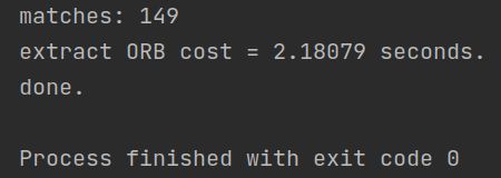
代码输出:

视觉SLAM入门 -- 学习笔记 - Part5_第5张图片
完整代码

最后,请结合实验,回答下面几个问题:
1. 为什么说ORB 是一种二进制特征?

答:因为ORB所用的Brief描述子采用的是0和1二进制表示。

2. 为什么在匹配时使用50 作为阈值,取更大或更小值会怎么样?

答:取更大值可能会有更多误匹配,取更小值则匹配得到的点会减少。

3. 暴力匹配在你的机器上表现如何?你能想到什么减少计算量的匹配方法吗?

答: VMware虚拟机用时: 2.18s, 可以通过限制match的范围来避免对keypoints2所有结果的多次遍历

3 从 E 恢复 R, t

我们在书中讲到了单目对极几何部分,可以通过本质矩阵E,得到旋转和平移R, t,但那时直接使用了OpenCV 提供的函数。本题中,请你根据数学原理,完成从E 到R, t 的计算。程序框架见code/E2Rt.cpp.

设Essential 矩阵E 的取值为(与书上实验数值相同):
视觉SLAM入门 -- 学习笔记 - Part5_第6张图片
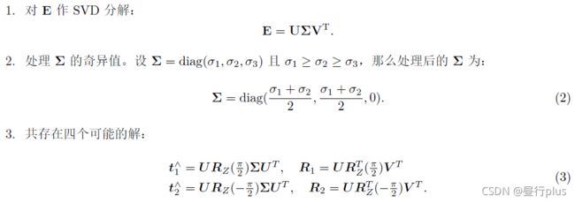
请计算对应的R; t,流程如下:
视觉SLAM入门 -- 学习笔记 - Part5_第7张图片

  • 其中U是n×n正交阵,V是p×p正交阵, Σ \Sigma Σ是n×p实正矩阵,其主对角线外为零;
  • Σ \Sigma Σ的对角线项称为E的奇异值,U和V分别称为E的左奇异向量和右奇异向量。
  • R Z ( π 2 ) R_{Z}(\frac{\pi }{2}) RZ(2π)表示沿Z 轴旋转90 度得到的旋转矩阵。

同时,由于-E 和E 等价,所以对任意一个t 或R 取负号,也会得到同样的结果。因此,从E 分解到t,R 时,一共存在四个可能的解。请打印这四个可能的R, t。

提示:用AngleAxis 或Sophus::SO3 计算 R Z ( π 2 ) R_{Z}(\frac{\pi }{2}) RZ(2π)

注:实际当中,可以利用深度值判断哪个解是真正的解,不过本题不作要求,只需打印四个可能的解即可。同时,你也可以验证t^R 应该与E只差一个乘法因子,并且与书上的实验结果亦只差一个乘法因子。

关于SVD的代码示例,可参考:http://eigen.tuxfamily.org/dox/classEigen_1_1JacobiSVD.html

E2Rt.cpp

//
// Created by daybeha on 2021/11/3.
// 本程序演示如何从Essential矩阵计算R,t
//

#include 
using namespace Eigen;

#include 
#include 

using namespace std;

int main(int argc, char **argv) {
     

    // 给定Essential矩阵
    Matrix3d E;
    E << -0.0203618550523477, -0.4007110038118445, -0.03324074249824097,
            0.3939270778216369, -0.03506401846698079, 0.5857110303721015,
            -0.006788487241438284, -0.5815434272915686, -0.01438258684486258;

    // 待计算的R,t
    Matrix3d R;
    Vector3d t;

    // SVD and fix sigular values
    // START YOUR CODE HERE
    JacobiSVD<MatrixXd> svd(E, ComputeThinU|ComputeThinV);

    // 计算U,V矩阵和sigma奇异值
    Matrix3d U = svd.matrixU();
    Matrix3d V = svd.matrixV();
    // compute SIGMA
    // compute by formula
    Matrix3d SIGMA = U.inverse()*E*V.transpose().inverse();
    //    处理奇异值
    VectorXd sigma_value = svd.singularValues();
    Vector3d sigma_value2={
     (sigma_value[0]+sigma_value[1])/2,(sigma_value[0]+sigma_value[1])/2,0};
    Matrix3d SIGMA2 = sigma_value2.asDiagonal(); // 转为对角阵
	//两种方式算的SIGMA是一样的
    cout<<"SIGMA=\n"<<SIGMA<<endl;
    cout<<"\nsigma_value=\n"<<sigma_value<<endl;
    cout<<"\nSIGMA2=\n"<<SIGMA<<endl;
    cout<<"\nsigma_value2=\n"<<sigma_value<<endl;


    // END YOUR CODE HERE

    // set t1, t2, R1, R2 
    // START YOUR CODE HERE
    Matrix3d RZ1 = AngleAxisd(M_PI/2, Vector3d(0,0,1)).toRotationMatrix();
    Matrix3d RZ2 = AngleAxisd(-M_PI/2, Vector3d(0,0,1)).toRotationMatrix();

    Matrix3d t_wedge1 = U * RZ1 * SIGMA2 * U.transpose();
    Matrix3d t_wedge2 = U * RZ2 * SIGMA2 * U.transpose();

    Matrix3d R1 = U * RZ1 * V.transpose();
    Matrix3d R2 = U * RZ2 * V.transpose();

    // END YOUR CODE HERE

    cout << "\nR1 = " << R1 << endl;
    cout << "\nR2 = " << R2 << endl;
    cout << "\nt1 = " << Sophus::SO3d::vee(t_wedge1) << endl;
    cout << "\nt2 = " << Sophus::SO3d::vee(t_wedge2) << endl;

    // check t^R=E up to scale
    Matrix3d tR = t_wedge1 * R1;
    cout << "t^R = " << tR << endl;

    return 0;
}

代码输出:
视觉SLAM入门 -- 学习笔记 - Part5_第8张图片

4 用G-N 实现Bundle Adjustment 中的位姿估计

Bundle Adjustment 并不神秘,它仅是一个目标函数为重投影误差的最小二乘。我们演示了Bundle Adjustment 可以由Ceres 和g2o 实现,并可用于PnP 当中的位姿估计。本题,你需要自己书写一个高斯牛顿法,实现用Bundle Adjustment 优化位姿的功能,求出相机位姿。严格来说,这是Bundle Adjustment的一部分,因为我们仅考虑了位姿,没有考虑点的更新。完整的BA 需要用到矩阵的稀疏性,我们留到第七节课介绍。
视觉SLAM入门 -- 学习笔记 - Part5_第9张图片
请你根据上述条件,用G-N 法求出最优位姿,初始估计为 T 0 T_{0} T0 = I。程序GN-BA.cpp 文件提供了大致的框架,请填写剩下的内容。

在书写程序过程中,回答下列问题:
1. 如何定义重投影误差?

答: e i = u i − 1 s i K e x p ( ξ ∧ ) P i e_{i} = u_{i} - \frac{1}{s_{i}} Kexp(\xi ^{\wedge})P_{i} ei=uisi1Kexp(ξ)Pi

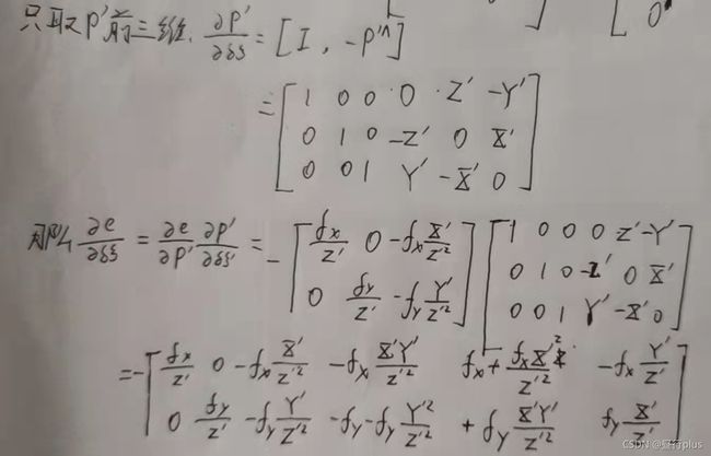
2. 该误差关于自变量的雅可比矩阵是什么?

视觉SLAM入门 -- 学习笔记 - Part5_第10张图片

至于公式②怎么来的,可以参考高博的《视觉SLAM十四讲》第二版,p85-86, SE(3)上的李代数求导

视觉SLAM入门 -- 学习笔记 - Part5_第11张图片
视觉SLAM入门 -- 学习笔记 - Part5_第12张图片
3. 解出更新量之后,如何更新至之前的估计上?

答:左乘exp(dx),扰动模型
对应代码:T_esti = Sophus::SE3d::exp(dx) * T_esti;

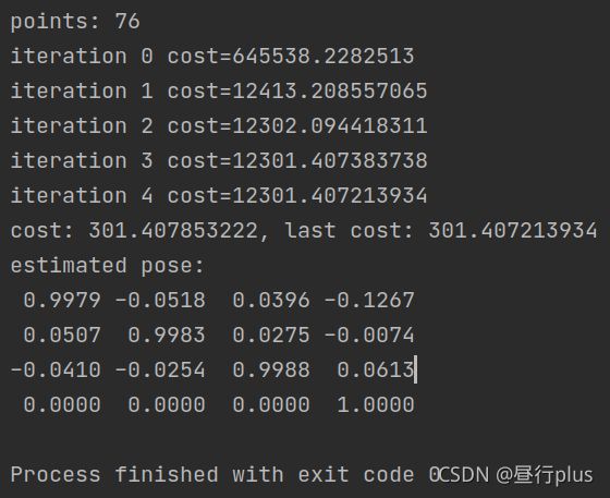
作为验证,最后估计得到的位姿应该接近:
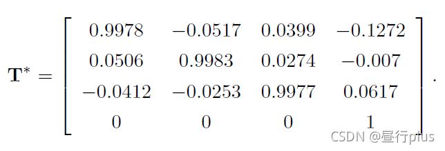
视觉SLAM入门 -- 学习笔记 - Part5_第13张图片
这和书中使用g2o 优化的结果很接近。
但是书中由于代码中错误地设置了depth scale(应该为5000,实际输入了1000),所以应该说和修正后结果相近。

高斯牛顿公式: J T J Δ x = − J T ∗ e J^{T}J\Delta x= -J^{T}*e JTJΔx=JTe

GN-BA.cpp

//
// Created by daybeha on 2021/11/3.
//

#include 
#include 

using namespace Eigen;

#include 
#include 
#include 
#include 

#include 

using namespace std;

typedef vector<Vector3d, Eigen::aligned_allocator<Vector3d>> VecVector3d;
typedef vector<Vector2d, Eigen::aligned_allocator<Vector3d>> VecVector2d;
typedef Matrix<double, 6, 1> Vector6d;

string p2d_file = "./p2d.txt";
string p3d_file = "./p3d.txt";


int main(int argc, char **argv) {
     

    VecVector2d p2d;
    VecVector3d p3d;
    Matrix3d K;
    double fx = 520.9, fy = 521.0, cx = 325.1, cy = 249.7;
    K << fx, 0, cx, 0, fy, cy, 0, 0, 1;

    // load points in to p3d and p2d 
    // START YOUR CODE HERE
    ifstream file_p2d(p2d_file);
    ifstream file_p3d(p3d_file);
    if(!file_p2d || !file_p3d){
     
        cout << "file not exist!" << endl;
    }
    while(!file_p2d.eof()){
     
        double x, y;
        file_p2d >> x >> y;
        Vector2d v(x,y);
        p2d.emplace_back(v);
    }
    while (!file_p3d.eof()){
     
        double x,y,z;
        file_p3d >> x >>y >>z;
        Vector3d v(x, y, z);
        p3d.emplace_back(v);
    }

    // END YOUR CODE HERE
    assert(p3d.size() == p2d.size());

    int iterations = 100;
    double cost = 0, lastCost = 0;
    int nPoints = p3d.size();
    cout << "points: " << nPoints << endl;

    Sophus::SE3d T_esti; // estimated pose

    for (int iter = 0; iter < iterations; iter++) {
     
        Matrix<double, 6, 6> H = Matrix<double, 6, 6>::Zero();
        Vector6d b = Vector6d::Zero();

        cost = 0;
        // compute cost
        for (int i = 0; i < nPoints; i++) {
     
            // compute cost for p3d[I] and p2d[I]
            // START YOUR CODE HERE
            double X = p3d[i][0];
            double Y = p3d[i][1];
            double Z = p3d[i][2];

            Vector3d P_ = T_esti*p3d[i];
            Vector2d u = Vector2d( fx * P_[0]/P_[2] + cx, fy*P_[1]/P_[2]+cy);
            Vector2d e = p2d[i] - u;
            cost+=e.squaredNorm();

	        // END YOUR CODE HERE

	    // compute jacobian
            Matrix<double, 2, 6> J;
            // START YOUR CODE HERE
            J << -fx/Z,         0,               fx*X/(Z*Z),
                fx*X*Y/(Z*Z),  -fx-fx*X*X/(Z*Z), fx*Y/Z,
                0,             -fy/Z,            fy*Y/(Z*Z),
                fy+fy*Y*Y/(Z*Z),-fy*X*Y/(Z*Z),   -fy*X/Z;

	        // END YOUR CODE HERE

            H += J.transpose() * J;
            b += -J.transpose() * e;
        }

	// solve dx 
        Vector6d dx;

        // START YOUR CODE HERE 
        dx = H.ldlt().solve(b);
        // END YOUR CODE HERE

        if (isnan(dx[0])) {
     
            cout << "result is nan!" << endl;
            break;
        }

        if (iter > 0 && cost >= lastCost) {
     
            // cost increase, update is not good
            cout << "cost: " << cost << ", last cost: " << lastCost << endl;
            break;
        }

        // update your estimation
        // START YOUR CODE HERE
        T_esti = Sophus::SE3d::exp(dx) * T_esti;

        // END YOUR CODE HERE
        
        lastCost = cost;
        
        cout << "iteration " << iter << " cost=" << cout.precision(12) << cost << endl;
    }

    cout.setf(ios::fixed);
    cout << "estimated pose: \n" << setprecision(4) << T_esti.matrix() << endl;
    return 0;
}

代码输出:
视觉SLAM入门 -- 学习笔记 - Part5_第14张图片

5 * 用ICP 实现轨迹对齐

在实际当中,我们经常需要比较两条轨迹之间的误差。第三节课习题中,你已经完成了两条轨迹之间的RMSE 误差计算。但是,由于ground-truth 轨迹与相机轨迹很可能不在一个参考系中,它们得到的轨迹并不能直接比较。这时,我们可以用ICP 来计算两条轨迹之间的相对旋转与平移,从而估计出两个参考系之间的差异。

图3: vicon 运动捕捉系统,部署于场地中的多个红外相机会捕捉目标球的运动轨迹,实现快速定位。
视觉SLAM入门 -- 学习笔记 - Part5_第15张图片
设真实轨迹为 T g T_{g} Tg,估计轨迹为 T e T_{e} Te,二者皆以 T W C T_{WC} TWC 格式存储。但是真实轨迹的坐标原点定义于外部某参考系中(取决于真实轨迹的采集方式,如Vicon 系统可能以某摄像头中心为参考系,见图3),而估计轨迹则以相机出发点为参考系(在视觉SLAM 中很常见)。由于这个原因,理论上的真实轨迹点与估计轨迹点应满足:

在这里插入图片描述
其中i 表示轨迹中的第 i 条记录, T g e T_{ge} Tge ∈ SE(3) 为两个坐标系之间的变换矩阵,该矩阵在整条轨迹中保持不变。 T g e T_{ge} Tge可以通过两条轨迹数据估计得到,但方法可能有若干种:

  1. 认为初始化时两个坐标系的差异就是 T g e T_{ge} Tge,即:
    在这里插入图片描述

  2. 在整条轨迹上利用最小二乘计算 T g e T_{ge} Tge

在这里插入图片描述
3. 把两条轨迹的平移部分看作点集,然后求点集之间的ICP,得到两组点之间的变换。

其中第三种也是实践中用的最广的一种。现在请你书写ICP 程序,估计两条轨迹之间的差异。轨迹文件在compare.txt 文件中,格式为:
在这里插入图片描述
time, t, q的具体格式:
视觉SLAM入门 -- 学习笔记 - Part5_第16张图片

其中t 表示平移,q 表示单位四元数。请计算两条轨迹之间的变换,然后将它们统一到一个参考系,并画在pangolin 中。轨迹的格式与先前相同,即以时间,平移,旋转四元数方式存储。
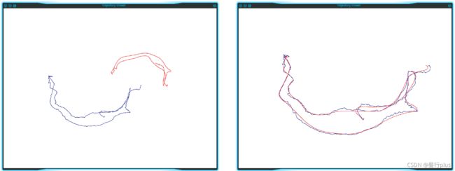
本题不提供代码框架,你可以利用之前的作业完成本题。图4 显示了对准前与对准后的两条轨迹。

图4: 轨迹对准前与对准后
视觉SLAM入门 -- 学习笔记 - Part5_第17张图片

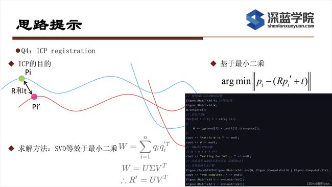
黑熊助教思路提示:
视觉SLAM入门 -- 学习笔记 - Part5_第18张图片

//
// Created by daybeha on 9/11/2021.
//

#include 
#include 
#include 
#include 
#include 
#include 
#include 


using namespace std;
using namespace cv;
using namespace Eigen;

typedef vector<Sophus::SE3d, Eigen::aligned_allocator<Sophus::SE3d>> TrajectoryType;
typedef vector<Vector3d> vecVector3d;

void ReadData(const string& FileName ,
              TrajectoryType &poses_e,
              TrajectoryType &poses_g,
              vecVector3d &t_e,
              vecVector3d &t_g
);

void DrawTrajectory(const TrajectoryType &poses_e,
                    const TrajectoryType &poses_g,
                    const string &window_name);


void icp_svd (const vecVector3d& pts1,
              const vecVector3d& pts2,
              Matrix3d & R,Vector3d& t);

int main(int argc, char ** argv){
     
    string compare_file = "./compare.txt";
    TrajectoryType poses_e, poses_g, poses_g_;
    vecVector3d t_e, t_g;
    ReadData(compare_file,poses_e, poses_g, t_e, t_g);

    DrawTrajectory(poses_e, poses_g, "Trajectory Before ICP");

    Matrix3d R;
    Vector3d t;
    icp_svd(t_e, t_g, R, t);
    Sophus::SE3d T_eg(R,t);
    for(auto SE3_g:poses_g){
     
        SE3_g = T_eg*SE3_g;      // T_e[i]=T_eg*T_g[i]
        poses_g_.push_back(SE3_g);
    }
    DrawTrajectory(poses_e,poses_g_, "Trajectory After ICP");


    return 0;
}

/*************读取文件中的位姿******************/
void ReadData(const string& FileName,TrajectoryType &poses_e,
              TrajectoryType &poses_g, vecVector3d &t_e,
              vecVector3d &t_g)
{
     
    double time, tx, ty, tz, qx, qy, qz, qw;
    ifstream file(FileName);
    if(!file){
     
        cout<<"compare.txt file can not open!"<<endl;
        return ;
    }
    while(!file.eof()){
     
        file >> time >> tx >> ty >> tz
             >> qx >> qy >> qz >> qw;
        Vector3d t = Vector3d(tx, ty, tz) ;
        Quaterniond q = Quaterniond(qw, qx, qy, qz).normalized(); //四元数的顺序要注意
        poses_e.emplace_back(q, t);
        t_e.emplace_back(t);

        file >> time >> tx >> ty >> tz
             >> qx >> qy >> qz >> qw;
        t = Vector3d(tx, ty, tz) ;
        q = Quaterniond(qw, qx, qy, qz).normalized();
        poses_g.emplace_back(q, t);
        t_g.emplace_back(t);
    }

}

void icp_svd (const vecVector3d& pts1,
              const vecVector3d& pts2,
              Matrix3d & R,Vector3d& t){
     
    // 计算质心 center of mass
    Vector3d p1, p2;
    int N = pts1.size();
    for (int i=0; i<N; i++){
     
        p1 += pts1[i];
        p2 += pts2[i];
    }
    p1 = p1 / N;
    p2 = p2 / N;

    // remove the center
    vecVector3d q1(N), q2(N);
    for ( int i=0; i<N; i++ )
    {
     
        q1[i] = pts1[i] - p1;
        q2[i] = pts2[i] - p2;
    }

    // compute q1*q2^T
    Eigen::Matrix3d W = Eigen::Matrix3d::Zero();
    for ( int i=0; i<N; i++ )
    {
     
        W += q1[i] * q2[i].transpose();
    }
    cout<<"W="<<W<<endl;

    // SVD on W
    Eigen::JacobiSVD<Matrix3d> svd(W, ComputeFullU|ComputeFullV);
    Eigen::Matrix3d U = svd.matrixU();
    Eigen::Matrix3d V = svd.matrixV();
    cout<<"U="<<U<<endl;
    cout<<"V="<<V<<endl;
    //p1=R_12*p_2 + t,注意R的意义,p2到p1的旋转关系
    R = U* V.transpose();
    t = p1 - R*p2;

    cout << "R= " << R << endl;
    cout << "t= " << t << endl;

}

/*****************************绘制轨迹*******************************************/
void DrawTrajectory(const TrajectoryType &poses_e,
                    const TrajectoryType &poses_g,
                    const string &window_name)
{
     

    if (poses_g.empty() || poses_e.empty()) {
     
        cerr << "Trajectory is empty!" << endl;
        return;
    }

    // create pangolin window and plot the trajectory
    pangolin::CreateWindowAndBind(window_name, 1024, 768); //创建一个窗口
    glEnable(GL_DEPTH_TEST); //启动深度测试
    glEnable(GL_BLEND); //启动混合
    glBlendFunc(GL_SRC_ALPHA, GL_ONE_MINUS_SRC_ALPHA); //混合函数glBlendFunc( GLenum sfactor , GLenum dfactor );sfactor 源混合因子dfactor 目标混合因子

    pangolin::OpenGlRenderState s_cam(
            pangolin::ProjectionMatrix(1024, 768, 500, 500, 512, 389, 0.1, 1000),
            pangolin::ModelViewLookAt(0, -0.1, -1.8, 0, 0, 0, 0.0, -1.0, 0.0) //对应的是gluLookAt,摄像机位置,参考点位置,up vector(上向量)
    );

    pangolin::View &d_cam = pangolin::CreateDisplay()
            .SetBounds(0.0, 1.0, pangolin::Attach::Pix(175), 1.0, -1024.0f / 768.0f)
            .SetHandler(new pangolin::Handler3D(s_cam));


    while (!pangolin::ShouldQuit()) {
     
        glClear(GL_COLOR_BUFFER_BIT | GL_DEPTH_BUFFER_BIT);

        d_cam.Activate(s_cam);
        glClearColor(1.0f, 1.0f, 1.0f, 1.0f);

        glLineWidth(2);
        for (size_t i = 0; i < poses_e.size() - 1; i++) {
     
            glColor3f(1 - (float) i / poses_e.size(), 0.0f, (float) i / poses_e.size());
            glBegin(GL_LINES);
            auto p1 = poses_e[i], p2 = poses_e[i + 1];
            glVertex3d(p1.translation()[0], p1.translation()[1], p1.translation()[2]);
            glVertex3d(p2.translation()[0], p2.translation()[1], p2.translation()[2]);
            glEnd();
        }

        for (size_t j = 0; j < poses_g.size() - 1; j++) {
     
            glColor3f(1 - (float) j / poses_g.size(), 0.0f, (float) j / poses_g.size());
            glBegin(GL_LINES);
            auto p1 = poses_g[j], p2 = poses_g[j + 1];
            glVertex3d(p1.translation()[0], p1.translation()[1], p1.translation()[2]);
            glVertex3d(p2.translation()[0], p2.translation()[1], p2.translation()[2]);
            glEnd();
        }

        pangolin::FinishFrame();
    }

}


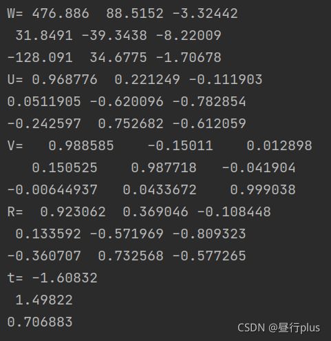
代码输出:
视觉SLAM入门 -- 学习笔记 - Part5_第19张图片

对准前:
视觉SLAM入门 -- 学习笔记 - Part5_第20张图片

对准后:
视觉SLAM入门 -- 学习笔记 - Part5_第21张图片

参考:

https://www.cnblogs.com/meteoric_cry/p/7987548.html
http://eigen.tuxfamily.org/dox/classEigen_1_1JacobiSVD.html
https://blog.csdn.net/weixin_41074793/article/details/85133424
https://blog.csdn.net/weixin_44218240/article/details/105924752?spm=1001.2014.3001.5501
https://blog.csdn.net/weixin_41074793/article/details/85133424
https://github.com/gaoxiang12/slambook2

你可能感兴趣的:(SLAM,计算机视觉,opencv,SLAM)