VLP-16用户手册 第九章 传感器数据
第九章 传感器数据
项目用到了VLP-16激光雷达,在看官方源代码时,很多地方不是很清楚,因此查看了用户手册,顺便翻译整理出来。本文翻译自VLP-16用户手册第9章内容,本章是手册的核心,说明了数据的结构以及使用方法。
PS:虽然大部分都是机器翻译,但是在不利于理解的地方,加上了本人注释,码字不容易,望转载时注明出处。
文章目录
- 第九章 传感器数据
- 9.1 传感器坐标系
- 9.2 球面坐标系转换为迪卡尔坐标系(XYZ)
- 9.3 数据包的类型及定义
-
- 9.3.1 定义
-
- 9.3.1.1 发射序列
- 9.3.1.2 激光通道
- 9.3.1.3 数据点
- 9.3.1.4 方位角(航向角)
- 9.3.1.5 数据块
- 9.3.1.6 时间戳
- 9.3.1.7 工厂字节
- 9.3.2 数据包结构
-
- 9.3.2.1 计算方位角(azimuth α)
- 9.3.2.2 计算距离(distance r)
- 9.3.2.3 计算时间戳(timestamp )
- 9.3.2.4 计算工厂字节(factory )
- 9.3.3 位置数据包结构(简略)
- 9.4 每个数据块精确时间戳计算
- 9.5 每个数据块精确方向角计算
- 9.6 将 PCAP 文件转换为点云格式
- 附一、返回模式
-
- 1.单回波模式(Single Return Modes):Strongest、Last
- 2.多返回(Multiple Returns )
- 3.双返回模式(Dual Return Mode )
9.1 传感器坐标系
传感器的数据是基于球坐标(半径 r、仰角 ω、方位角 α)描述相对于原点的距离。
The sensor reports distances relative to itself in spherical coordinates (radius r, elevation ω, azimuth α).
传感器数据原点 (0,0,0) 位于中心轴上,传感器底座上方 37.7 mm 处,如下页图 9-1 所示(参见侧视图和俯视图),其中还说明了传感器的坐标系定义。
Sensor data origin (0,0,0) is 37.7 mm above the sensor base, on the center axis, as shown in Figure 9-1 on the next page (see the side and top views), which also shows the sensor’s frame of reference.
图9-1 传感器坐标系统
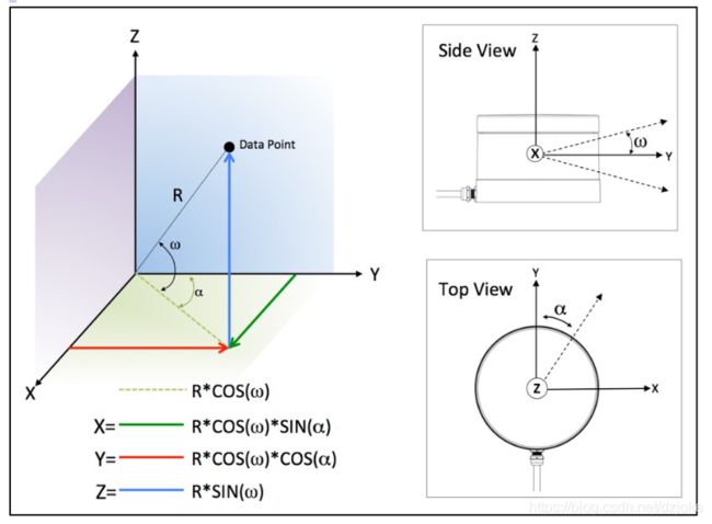
采用右手坐标系,线缆正前方为Y轴正向,右侧为X轴正向,Z轴垂直于地面向上。航向角(α)以Y轴为起点,逆时针增加,代表激光雷达水平扫描的角度。俯仰角(ω)以X-Y平面为起点,向上为正,向下为负,代表每个激光发射器出线角度,VLP-16有16对激光器,在出厂时已固定了角度,表9-1描述了各个激光器对应的角度。
表9-1 激光ID对应的角度及垂直校正值(后面会用到)
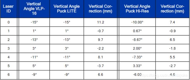
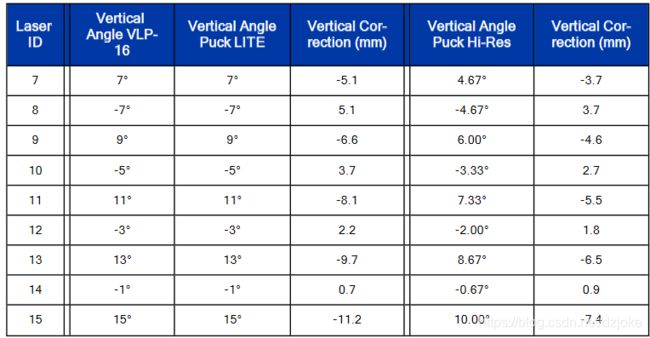
注意:本表按发射顺序列出了激光器,虽然VLP-16的激光按物理位置排列成了一个垂直列,但发射顺序是从最底部的一束开始,接着是水平面向上的第一束,然后依次进行,每次发射间隔7个激光束,这样做的好处是为了避免激光束之间“串扰”或者干扰。
Note: Table 9-1 on the previous page lists lasers in the order they are fired. Though the VLP-16’s lasers are organized in a single, vertical column, they are not fired from one end to the other. Instead, the firing sequence “hops around.” This is to avoid “cross-talk” or interference.
9.2 球面坐标系转换为迪卡尔坐标系(XYZ)
原始数据需要进行计算才能将传感器的球面数据(半径 r、仰角 ω、方位角 α)转换为笛卡尔坐标。
A computation is necessary to convert the spherical data (radius r, elevation ω, azimuth α) from the sensor to Cartesian coordinates.
算法如图9-1中所示,分别计算X,Y,Z值。
Figure 9-1 on the next page lists the formulas for converting spherical coordinates (R, ω, α) to Cartesian coordinates (X, Y, Z).
计算 X、Y、Z 后,应用表 9-1 中的垂直校正以获得最大精度。 垂直校正表示发送的激光束相对于传感器原点的垂直偏移。 这些垂直偏移校正也可在手册的第 105 页的 VLP-16中找到。
After computing X,Y,Z, apply the vertical correction in Table 9-1 on the previous page for greatest accuracy. This represents the vertical offset of the laser with respect to sensor origin. These vertical offset corrections are also found in the VLP-16 and Puck LITE Optical Drawing on page 105 and the Hi-Res version below it.
9.3 数据包的类型及定义
传感器产生两种类型的数据包:数据包和位置数据包。 位置数据包包含一些传感 器的辅助信息,也被称为遥测数据包或 GPS 数据包。
There are two types of packets generated by the sensor: Data packets and Position packets. Position packets are sometimes referred to as telemetry packets, or GPS packets.
PS:两种包通过两个不同的端口传输,官方源码提供了数据包(端口:2368)的数据采集及解析,位置数据包一般未使用,需要自己实现采集。
数据包包含传感器测量的 3D 数据以及物体表面的已经过校准的反射率。
Data packets contain the 3D data measured by the sensor as well as the calibrated reflectivity of the surface from which the light pulse was returned.
数据包中还包含一组方位角(2字节)和一个 4 字节的时间戳,以及传感器型号标识和激光工作模式的2字节的工厂参数。通过区分激光雷达型号和返回模式,可使您的软件自动适应不同数据格式进行解析。
Also contained in the data packet is a set of azimuths and a 4-byte timestamp, as well as two factory bytes identifying the model of sensor and the laser return mode. Knowing the model and return mode provides the information your software needs to automatically adjust to different data formats.
如果启用了 GPS 时间源同步,则位置数据包会提供最后收到的 NMEA 消息(GPRMC 或 GPGGA)的副本。详细信息,请参阅手册第 41 页的 GPS、每秒脉冲数 (PPS) 和 NMEA 的相关描述。位置数据包还提供一个字节,用于标识 PPS 信号与时间源同步的状态。越新的固件提供了更多信息。
Position packets provide a copy of the last NMEA message received (either GPRMC or GPGGA) if you’ve configured your sensor to synchronize with a GPS time source. See GPS, Pulse Per Second (PPS) and NMEA Sentence on page 41 for additional information. Position packets also provide a byte identifying the state of the PPS signal for synchronizing with a time source. Newer firmware provides even more information.
在这两种类型的数据包中,多字节值(例如方位角、距离和时间戳)以小端方式传输,即低字节在前,高字节在后。
Note: In both types of packets, multi-byte values (e.g. azimuth, distance, and timestamp) are transmitted with the least
significant byte first (i.e. little-endian).
9.3.1 定义
本节提供了传感器数据包结构的说明(最核心部分)
9.3.1.1 发射序列
当传感器的所有激光都工作时,就会产生发射序列,即发射顺序。每种产品(比如VLP-16,128线激光雷达)都有固有的发射顺序。整个激光工作周期除了发射时间外,还包括充电时间。发射序列有时也被称为发射组(可能128线同时会发射几束激光)。一个数据包里一定包含一次完整的发射序列(即16线激光都完整发射)
A firing sequence occurs when all the lasers in a sensor are fired.They are fired in a sequence specific to a given product line or model.They are fired in a sequence specific to a given product line or model. Laser recharge time is included. A firing sequence is sometimes referred to as a firing group. A firing sequence is not allowed to span multiple data packets.
VLP-16 发射所有 16 个激光器并充电需要 55.296 μs。即一个完整发射周期是55.296us。
it takes 55.296 μs to fire all 16 lasers in a VLP-16 and recharge.
9.3.1.2 激光通道
一个激光通道包含 903 nm 的激光发射器和检测器对。每个激光通道固定在相对于传感器水平面的特定仰角。每个激光通道都有自己的激光 ID 号。由于特定通道的水平仰角总是固定的,发射顺序也是固定的,与接收到的数据包顺序一致,因此在传输的数据包中不会有此值,是通过文档来告知相关信息(表9-1),从而推断具体的值。
A laser channel is a single 903 nm laser emitter and detector pair. Each laser channel is fixed at a particular elevation angle relative to the horizontal plane of the sensor. Each laser channel is given its own Laser ID number. Since the elevation angle of a particular laser channel doesn’t change, it doesn’t appear in data packets. Its value is inferred by a data point’s location in a data packet.
9.3.1.3 数据点
数据点即激光器对物体的距离与反射率的测量值。
A data point is a measurement by one laser channel of a reflection of a laser pulse.
数据点由三个字节表示 - 两个字节的距离和一个字节的校准反射率。
A data point is represented in the packet by three bytes - two bytes of distance and one byte of calibrated reflectivity.
距离值是一个无符号整数(unsigned int), 它有2毫米的粒度, 因此,收到的值为 51,154 表示 102,308 mm 或 102.308 m。
The distance is an unsigned integer. It has 2 mm granularity. Hence, a reported value of 51,154 represents 102,308 mm or 102.308 m.
校准反射率以 0 到 255 的比例表示,如本手册第 32 页上的校准反射率中所述。仰角 (ω) 是根据数据块内数据点的位置推断出来的。
Calibrated reflectivity is reported on a scale of 0 to 255 as described in Calibrated Reflectivity on page 32. The elevation angle (ω) is inferred based on the position of the data point within a data block.
距离为 0 表示未测量到值。 当激光关闭、故障或未及时返回(比如射向天空)时可能测量到的值。
A distance of 0 indicates a non-measurement. The laser is either off or a measurable reflection was not returned in time。
9.3.1.4 方位角(航向角)
在每个数据块开头的标志字节之后的两字节即为方位角值 (α)。
A two-byte azimuth value (α) appears after the flag bytes at the beginning of each data block.
方位角是一个无符号整数(unsigned int),它表示角度值的100倍。 比如原始值 27742实际为 277.42°。
The azimuth is an unsigned integer. It represents an angle in hundredths of a degree. Therefore, a raw value of 27742 should be interpreted as 277.42°.
方位角的有效值范围为 0 到 35999。每个数据块仅报告一个方位角值。
Valid values for azimuth range from 0 to 35999. Only one azimuth value is reported per data block.
9.3.1.5 数据块
每个数据块中包含来自 16 个激光器的两个发射序列的信息。每个数据包包含来自 12 个数据块中的 24 个发射序列的数据。即1 packt=12 blocks;1blocks=2 fire sequences;1 fire sequences=16 lasers;
The information from two firing sequences of 16 lasers is contained in each data block. Each packet contains the data from 24 firing sequences in 12 data blocks.
每个数据块只返回一个方位角。
Only one Azimuth is returned per data block.
一个数据块由 100 个字节的二进制数据组成:
- 开始标志flag(0xFFEE) 2字节
- 航向角 (α) 2字节
- 数据点 16 laser X 2 sequences X 3字节
[2+2+16X2X3]=100
A data block consists of 100 bytes of binary data: - A two-byte flag (0xFFEE)
- A two-byte Azimuth
- 32 Data Points
[2 + 2 + (32 × 3)] = 100 bytes
为了计算时间偏移,建议将数据包中的数据块编号为 0 到 11。
For calculating time offsets it is recommended that the data blocks in a packet be numbered 0 to 11.
9.3.1.6 时间戳
时间戳是一个 4字节 32 位无符号整数(unsigned int),用于标记第一个数据块的第一个触发序列中第一个数据点的时刻 (事实上官网源码中整包采用的时间戳给这个值加了个参数,是否选择第一个数据点的时刻,而默认是采用最后一包的时间戳,最后用第一个数据点与最后一个数据点作平均)。
The four-byte time stamp is a 32-bit unsigned integer marking the moment of the first data point in the first firing sequence of the first data block.
时间戳的值是自小时开始以来经过的微秒数。数字范围从 0 到 3,599,999,999,即一小时内的微秒数 (即最大值为1小时,而后舍去小时,重新计时)。
The time stamp’s value is the number of microseconds elapsed since the top of the hour.The number ranges from 0 to 3,599,999,999, the number of microseconds in one hour.
时间戳很重要,因为地理参考软件使用它来将每次激光发射与来自惯性导航系统的相应数据进行匹配 (即系统内时间同步非常重要,用于传感器融合等应用) 。
The time stamp is critical because it’s used by geo-referencing software to match each laser firing with corresponding data from an inertial navigation system.
惯性导航系统为俯仰、滚转、偏航、纬度、经度和高度提供了一系列时间戳值。
The inertial navigation system provides a series of time stamped values for pitch, roll, yaw, latitude, longitude, and elevation.
通过将数据点的时间与来自 INS 的带时间戳的数据相匹配,用户的软件可以将数据从传感器的坐标系以数学方式转换为基于地球的参考系。
By matching the time of the data point to the time-stamped data from the INS, the user’s software can mathematically transform the data from the sensor’s coordinate frame to an earth-based reference frame.
时间戳与 GPS/INS 提供的世界协调时间 (UTC) 匹配 (激光雷达可接入GPS时间等时钟源,用来更精确计时)。
The time stamps are matched to Universal Coordinated Time (UTC) provided by the GPS/INS.
当传感器通电时,便开始使用内部时间参考计算微秒。 但是,传感器可以将其数据与 UTC 时间同步,因此您可以确定任何特定数据包中每个激光器的确切发射时间。
When the sensor powers up it begins counting microseconds using an internal time reference. However, the sensor can synchronize its data with UTC time so you can ascertain the exact firing time of each laser in any particular packet.
UTC 同步需要用户提供的 GPS/INS 接收器生成同步脉冲每秒 (PPS) 信号和 NMEA GPRMC 消息。GPRMC 消息以 UTC 格式提供分钟和秒。同步后,传感器从 GPRMC 消息中读取分钟和秒,并使用该信息将传感器的时间戳设置为每 UTC 时间过去一小时的微秒数。
UTC synchronization requires a user-supplied GPS/INS receiver generating a synchronizing Pulse Per Second (PPS) signal and an NMEA GPRMC message. The GPRMC message provides minutes and seconds in UTC.Upon synchronization, the sensor reads the minutes and seconds from the GPRMC message and uses the information to set the sensor’s time stamp to the number of microseconds past the hour, per UTC.
注意:有关电气和计时要求的完整说明,请参见本手册第 41 页的 GPS、每秒脉冲 (PPS) 和 NMEA 句子。有关计时选项的完整说明,请参见第 125 页的时间同步。 Note: A full description of electrical and timing requirements can be found in GPS, Pulse Per Second (PPS) and NMEA Sentence on page 41. A full description of timing options can be found in Time Synchronization on page 125.
9.3.1.7 工厂字节
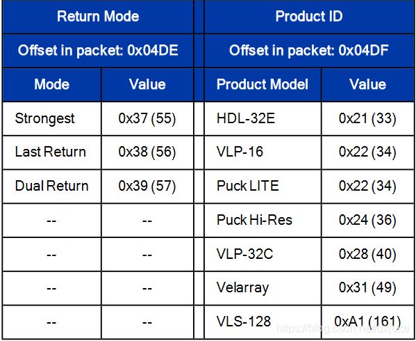
从固件版本 3.0.29.0 开始,每个数据包都包含一对称为工厂字节的字节。它们的值指示方位角和数据点在数据包中的组织方式。它们的数据包位置、值和含义在下表 9-2 中指定。
Beginning with firmware release 3.0.29.0, every data packet includes a pair of bytes called the Factory Bytes.Their values indicate how azimuths and data points are organized in the packet.Their packet locations, values, and meanings are specified in Table 9-2 below.
返回模式字节指示数据包的方位角和数据点是如何组织的 (单回波与双回波的方位角意义或者值排列不同)。有关详细信息,请参阅下面的数据包结构。
The Return Mode byte indicates how the packet’s azimuth and data points are organized. See Data Packet Structure below for details.
每条传感器型号系列的激光器都以略微不同的角度垂直排列。使用产品 ID 字节来识别正确的垂直(或仰角)角组。
Every sensor model line has its lasers arrayed vertically at slightly different angles. Use the Product ID byte to identify the correct set of vertical (or elevation) angles.
产品 ID 不是唯一的,可能由不同的传感器共享。例如,根据下表 9-2,VLP-16 和 Puck LITE 共享相同的仰角。因此,这两个产品共享相同的产品 ID。相反,Puck Hi-Res 具有不同的产品 ID,因为它具有一组不同的仰角。
Product IDs are not unique and may be shared by different sensors. For example, per Table 9-2 below, the VLP-16 and Puck LITE share the same elevation angles. Hence, the two products share the same Product ID. Conversely, the Puck Hi-Res has a different Product ID since it has a different set of elevation angles.
9.3.2 数据包结构
一个数据包长 1248 字节,通过 UDP 数据包在端口 2368 上发送。数据包由 42 字节的协议头、12 个数据块、一个 4 字节的时间戳和两个工厂字节组成。
A data packet is 1248 bytes long and sent via a UDP packet on port 2368. The data packet is comprised of 42 bytes of protocol header, twelve Data Blocks, a four-byte timestamp, and two factory bytes.
总共有两种格式的数据包:
- 单回波模式(分为强返回或者最后返回)
- 双回波模式
There are two formats for the data packet:
- Single Return Mode (either Strongest or Last)
- Dual Return Mode
请参阅第 32 页上的激光返回模式以了解最强、最后和双回在此上下文中的含义 (在文后有解释,见附一) 。
See Laser Return Modes on page 32 for an illustration of what Strongest, Last, and Dual mean in this context.
单回波的数据包结构如下图 9-2 所示。双回波的数据包结构如图 9-3 所示。
The packet data structure for Single Return Mode is shown in Figure 9-2 below. The packet data structure for Dual Return Mode is shown in Figure 9-3 on the facing page.
数据包结构之间有几个主要区别。
There are several key differences between the packet structures.
首先,在双回波模式下,传感器为每个方位角发射发送一对数据块 (即一个方位角在相邻的两个数据块是相同的)。奇数块 (1, 3, …, 9, 11) 包含最强或第二强的回波数据,偶数块 (0, 2, …, 8, 10) 包含最后一个回波数据 (可能是最远的)。
First, in Dual Return Mode the sensor sends a pair of data blocks for each azimuth angle firing. The odd numbered blocks (1, 3, …, 9, 11) contain either the strongest or second-strongest return and the even numbered blocks (0, 2, …, 8, 10) contain the last return.
如果最强的回波同时也是最后的回波,则(奇数块)提供次强的回报。如果仅检测到一次返回,则偶数|奇数块对(0|1、2|3、4|5、6|7、8|9、10|11)中的数据将相同。
If the strongest return is also the last return, then the second-strongest return is provided. If only one return was detected, the data will be identical in the even|odd block pairs (0|1, 2|3, 4|5, 6|7, 8|9, 10|11).
图9-2 单回波模式数据结构
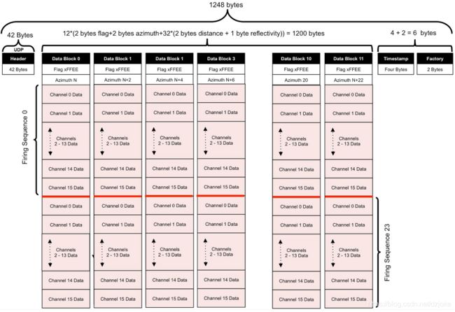 图9-3 双回波模式数据结构
 下图显示了 Wireshark抓取的单返回模式下单个数据包。图 9-4 显示了数据包的开始,图 9-5 显示了数据包的结束。数据相对于数据包中初始字节的位置/偏移显示在括号中。
The figures below show a Wireshark trace of a single packet in Single Return Mode. Figure 9-4 on the next page shows the beginning of the packet and Figure 9-5 on the next page shows packet end. The location/offset of the data relative to the initial byte in the packet is shown in parentheses.
图9-4 单回波数据跟踪(开始)
 图9-5 双回波数据跟踪(结束)
 注意图中同时给出了数据的解析方法
9.3.2.1 计算方位角(azimuth α)
- 获取数据(数据块的第3,4位,16进制):33,71
- 反转位置(小端传输,低字节在前):71,33
- 合成数据(直接组合,实际上等同于高*0x100(256)+低):7133
- 转化为10进制:28979
- 实际值除以100,结果为:289.79°
9.3.2.2 计算距离(distance r)
- 获取数据(16进制):89,59
- 反转位置(小端传输,低字节在前):59,89
- 合成数据(直接组合,实际上等同于高*0x100(256)+低):5989
- 转化为10进制:22921
- 实际值乘以2(以2mm 为粒度),结果为:45842mm
- 换算成米,除以1000,结果为:45.842m
9.3.2.3 计算时间戳(timestamp )
- 获取数据(16进制):61,67,B9,5A
- 反转位置(小端传输,低字节在前):5A,B9,67,61
- 合成数据(直接组合,实际上等同于按位移动8的n倍次):5AB96761
- 转化为10进制(微秒us):1 522 100 065
- us转化为s,除以1 000 000 ,结果为:1 522.100065 s
9.3.2.4 计算工厂字节(factory )
- 图9-5中第 0x04DE 位数据:0x39 ,查表9-1 ,表示双回波模式
- 图9-5中第 0x04DF 位数据:0x22 ,查表9-1 ,表示由VLP-16产生的数据
9.3.3 位置数据包结构(简略)
一般未使用,不做翻译,官方源码包也未做解析。
9.4 每个数据块精确时间戳计算
为了对 LiDAR 数据进行地理坐标系变换,建议计算特定激光发射的确切时间,以便与系统内其它 INS 的时间戳数据同步。(或者提高转换的精确度) 通过使用图 9-7 中给出的触发时间信息,您可以计算每个数据点的准确触发时间。
For the purpose of geo-referencing LiDAR data, it is helpful to calculate the exact moment of a particular laser firing in order to more closely associate it with time stamped data from an INS. By using the firing timing information given in Figure 9-7 on the next page you are able to compute the exact firing time for each data point.
图9-7 发射时间序列
 一个完整的激光工作周期是55.296us,包含16个激光器依序发射时间以及充电时间。每个激光器发射间隔周期2.304us,因此16个激光器发射总共需要16*2.304us,充电时间是18.432us。
- 55.296us=2.304us*16+18.432us
All sixteen lasers are fired and recharged every 55.296 μs. The cycle time between firings is 2.304 μs. There are 16 firings (16 × 2.304 μs) followed by a recharge period of 18.43 μs. Therefore, the timing cycle to fire and recharge all 16 lasers is given by (16 × 2.304 μs) + 18.43 μs = 55.296 μs.
要计算数据包中每个数据点的准确时间(以微秒为单位),首先将触发序列中的点编号为 0 到 15,这将成为您计算的数据点索引(又名激光 ID),接下来,将发射序列编号为 0 到 23,这将成为您的序列索引。需要与接收到的数据格式对应,即一个数据块表示一个发射通道,每个发射通道由16个激光收到的两个回波值,后面会继续讲。
To calculate the exact time, in microseconds, of each data point in a packet, first number the points in the firing sequence from 0 to 15. This becomes the data point index (aka Laser ID) for your calculations. Next, number the firing sequences 0 to 23. This becomes your sequence index.
数据包中的时间戳表示数据包中第一个数据点的时间。您需要计算每个数据点的时间偏移量,然后将该偏移量与时间戳叠加。有关特定数据点时序偏移(单返回模式)的信息,请参见第 66 页的图 9-9,有关特定数据点时序偏移(双返回模式)的信息,请参见第 67 页的图 9-10。
The timestamp in the packet indicates the time of the first data point in the packet. You’ll need to calculate a time offset for each data point and then add that offset to the timestamp. See Figure 9-9 on page 66 for specific Data Point Timing Offsets (Single Return Mode) and Figure 9-10 on page 67 for specific Data Point Timing Offsets (Dual Return Mode).
计算时间偏移的算法:
- 第一步,计算每个数据点的时间偏移(每列数据块占一个发射周期,每个数据块内每个激光发射时间不同):
TimeOffset = (55.296 μs * SequenceIndex) + (2.304 μs * DataPointIndex)
- 第二步,叠加整个数据包起始的时间戳:
ExactPointTime = Timestamp + TimeOffset
举例:在单回波或双回波模式下,计算数据包中每个点的时序偏移,Python 代码如下:
def make_table(dual_mode):
         timing_offsets = [[0.0 for x in range(12)] for y in range(32)]
         # Init matrix
         # constants
         full_firing_cycle = 55.296 # μs
         single_firing = 2.304 # μs
         # compute timing offsets
         # x 指 包内有12个数据块     y 指 一个数据块内总共有32组数据点
         # 本指南按图9-8的行列排列,x指列,y指行,timing_offsets[y][x]
         # 与物理世界的理解,即先块,再块内的序号timing_offsets[x][y]有理解上的障碍
         for x in range(12):
             for y in range(32):
                 if dual_mode:
                     dataBlockIndex = (x - (x % 2)) + (y / 16)
                     # 双回波模式下,相邻两个数据块由同一个激光器发射的数据,其时间偏移一致
                     # 但是同一个数据块下,后16个数据点是第二个发射周期的数据
                 else:
                     dataBlockIndex = (x * 2) + (y / 16)
                     # 单回波模式下,每16个数据点发射周期增加
                 dataPointIndex = y % 16
                 timing_offsets[y][x] = \
                     (full_firing_cycle * dataBlockIndex) + (single_firing * dataPointIndex)
         return timing_offsets
The offset equation is given by:
TimeOffset = (55.296 μs * SequenceIndex) + (2.304 μs * DataPointIndex)
To calculate the exact point time, add the TimeOffset to the timestamp.
ExactPointTime = Timestamp + TimeOffset
Example: Calculate the timing offsets of every point in a packet, in single or dual return mode. The following is working Python code:
def make_table(dual_mode):
     timing_offsets = [[0.0 for x in range(12)] for y in range(32)] # Init matrix
     # constants
     full_firing_cycle = 55.296 # μs
     single_firing = 2.304 # μs
     # compute timing offsets
     for x in range(12):
         for y in range(32):
             if dual_mode:
                 dataBlockIndex = (x - (x % 2)) + (y / 16)
             else:
                 dataBlockIndex = (x * 2) + (y / 16)
             dataPointIndex = y % 16
             timing_offsets[y][x] = \
                 (full_firing_cycle * dataBlockIndex) + (single_firing * dataPointIndex)
     return timing_offsets
要验证这些值是否正确,您可以将它们打印出来并与第 66 页的图 9-9 和第 67 页的图 9-10 中的值进行比较。
To verify the values are correct, you can print them out and compare them with values in Figure 9-9 on page 66 and Figure 9-10 on page 67.
     timing_offsets = make_table(False)  # False : single return mode
     print('\n'.join([', '.join(['{:8.3f}'.format(value) for value in row])
              for row in timing_offsets]))
示例:如果时间戳值为 45,231,878 μs,则计算数据包中最后一次触发的确切触发时间。
Example: Calculate the exact firing time of the last firing in a packet if the timestamp value is 45,231,878 μs.
 Timestamp = 45,231,878 μs
 TimeOffset = timing_offsets[15][23]
 ExactPointTime = Timestamp + TimeOffset
 ExactPointTime = 45,231,878 + 1,306.368 μs
 ExactPointTime = 45,233,184.368 μs
下面的图 9-8 显示了特定数据点的时间偏移计算过程。
Figure 9-8 below shows the timing calculation for a specific data point.
由于激光发射周期是固定的,数据格式也是固定的,因此单/双回波的时间偏移数据可以通过查表获得
图9-9 单回波时间偏移表(us)
图9-10 双回波时间偏移表(us)
9.5 每个数据块精确方向角计算
传感器在每个数据块中报告的方位角 (α) 是发射序列中第一个激光发射时的方位角。
The azimuth (α) reported by the sensor in each data block is the azimuth at the moment the first laser in a firing sequence fires.
为了在地理坐标变换时获得更好的精度,由于每个数据点本身的发射时间不同 (同时激光雷达在水平方向上旋转,所以每个数据点的方向角也有些许不同),也需要精确计算每个数据点的方位角。可以使用图 9-9 和图 9-10 中显示的定时偏移来计算/插入这些精确方位角。
To get better precision when geo-referencing, it’s useful to precisely calculate the unique azimuth for each point by accounting for the firing timing. These precision azimuths may be calculated/interpolated using the timing offsets shown in Figure 9-9 on the previous page and Figure 9-10 above.
考虑具有 12 个数据块的单个数据包。如果假设转速在每个数据块中的两个 55.296 μs 发射序列上是恒定的 (假设激光雷达转速是恒定的,匀速圆周运动),您可以使用下面的算法来估计每个点的更精确的方位角。
Consider a single data packet with 12 data blocks. If you assume the rotational speed is constant over the two 55.296 μs firing sequences in each data block, you can use the algorithm below to estimate a more precise azimuth angle for each point.
下面用伪代码的方式实现:
The pseudo code below illustrates the concept.
- K 表示第 N 个数据块中某个数据点的索引,其有效范围为 0 到 31。
- 对每个数据块执行此操作
K represents an index to a data point in the Nth data block, where its valid range is 0 to 31.
Do this for each data block.
     // First, adjust for an Azimuth rollover from 359.99° to 0°
     If (Azimuth[datablock_n+1] < Azimuth[datablock_n])
     Then
         Azimuth[datablock_n+1] := Azimuth[datablock_n+1] + 360;
     Endif;

     // Determine the Azimuth Gap between data blocks
     // AzimuthGap 是相邻两个数据块的角度差,可能激光雷达在每个数据块发送前做了方向角校准,
     //使当前数据块的航向角更精确,那么相邻两个航向角之差就能得到比转360°/1圈更精确的精度
     //更何况相邻数据的方向角更容易实时获取
     //缺点是跨包后相邻两个角度差的获取,即第12块的方向角与下包的第一块方向角之差,包的接收顺序一定不能错。
     AzimuthGap = Azimuth[datablock_n+1] - Azimuth[datablock_n];

     // Perform the interpolation using the timing firing
     K = 0;
     While (K < 31)
         // Determine if you’re in the first or second firing sequence of the data block
         // 分成一个数据块上下两个部分情况
         if (K < 16)
         Then
             // Interpolate
             // 比例插值
             Precision_Azimuth[K] := Azimuth[datablock_n] + (AzimuthGap * 2.304 μs * K) /
55.296 μs);
         Else
             // Interpolate
             // 比例插值,统一按模块跨度的精度范围
             // (AzimuthGap * 2.304 μs * (K-16) /  55.296 μs 将使精度不统一
             Precision_Azimuth[K] := Azimuth[datablock_n] + (AzimuthGap * 2.304 μs * ((K-16) + 55.296 μs)) / (2 * 55.296 μs);
         Endif

         // Adjust for any rollover
         If Precision_Azimuth[K] >= 360
         Then
             Precision_Azimuth[K] := Precision_Azimuth[K] – 360;
         Endif

         K++;
     End While
注意:如果您检查 GITHUB 中的 VeloView 代码,您会注意到 VeloView 使用稍微不同的方法来计算 XYZ 坐标。VeloView 的方位角定义,是原点与 X 轴为起点, 逆时针正增加。
Note : If you examine the VeloView code in GITHUB, you’ll notice that VeloView uses a slightly different method to calculate XYZ coordinates. VeloView operates on the azimuth as if it were read as positive in the counter-clockwise direction with the origin along the X axis.
9.6 将 PCAP 文件转换为点云格式
将 Velodyne LiDAR 数据的数据包捕获 (pcap) 文件转换为 LAS、LAZ、XYZ、PLY 或其他点云文件格式可能是一个非常重要的过程。
Converting a packet capture (pcap) file of Velodyne LiDAR data to a LAS, LAZ, XYZ, PLY, or other point cloud file format can be a non-trivial process.
传感器在 pcap 文件中提供的数据是相对于传感器的参考系测量的 - 传感器的内部三维坐标系与传感器一起移动。这与数据点引用到单个坐标系的点云文件明显不同。 该坐标系可能是地球坐标系(纬度、经度、高程)或其他方便的参考坐标系。
The data provided by the sensor in the pcap file is measured relative to the sensor’s reference frame - the sensor’s internal three dimensional coordinate system which moves with the sensor. That’s markedly different from a point cloud file where the data points are referenced to a single coordinate system. That coordinate system might be an earth-frame (latitude, longitude, elevation) or another convenient reference frame.
将原始 LiDAR 数据处理成点云称为地理参考。在地理参考中,用户在每次测量时都会考虑传感器的位置 (X/Y/Z) 和方向(俯仰/滚动/偏航)。了解这六个值使用户能够执行正确的数学旋转和平移,以将 LiDAR 数据引用到单个坐标系中。
Processing the raw LiDAR data into a point cloud is called geo-referencing. In geo-referencing, the user takes into account the sensor’s position (X/Y/Z) and orientation (pitch/roll/yaw) for each measurement. Knowing these six values enables a user to perform the proper mathematical rotations and translations to reference the LiDAR data into a single coordinate system.
Velodyne LiDAR 客户主要应用于是惯性系统和SLAM技术。
Two popular techniques Velodyne LiDAR customers use for geo-referencing are inertial referencing and Simultaneous Localization and Mapping (SLAM).
通过惯性参考,传感器在每一刻的位置和方向都被惯性导航系统 (INS) 记录下来。INS 可以包括全球定位系统 (GPS) 接收器和惯性测量单元 (IMU)。来自 INS 和 LiDAR 传感器的数据与 GPS 卫星的参考时钟时间同步,使用户能够将每个 LiDAR 数据点与其来自 INS 的相应位置和方向进行匹配。将 LiDAR 数据与 INS 数据匹配后,每个测量值都被数学转换为单个坐标系。
With inertial referencing, the location and orientation of the sensor at every moment is recorded with an Inertial Navigation System (INS). An INS combines a Global Positioning System (GPS) receiver with an Inertial Measurement Unit (IMU). Data from the both the INS and LiDAR sensor are time-synchronized to the GPS satellite’s reference clock, enabling the user to match each LiDAR data point with its corresponding position and orientation from the INS. Having matched the LiDAR data with the INS data, each measurement is mathematically translated into a single coordinate system.
附一、返回模式
VLP-16 支持三种激光返回模式:Strongest、Last 和 Dual。
The VLP-16 supports three laser return modes: Strongest, Last, and Dual.
可以通过传感器的 Web 界面配置以其中一种方式返回(其中设置称为返回类型–Return Type)或通过curl命令配置。(有关设置激光返回模式的其他信息,请参阅第 71 页的配置屏幕或第 78 页的curl 命令。)
A sensor can be configured to handle laser returns in one of these ways interactively via the sensor’s web interface (where the setting is called Return Type) or programmatically via curl command. (See Configuration Screen on page 71 or Sensor Control with curl on page 78 for additional information related to setting laser return modes.)
激光返回是对反射的检测。 VLP-16 支持每次激光发射最多两次返回。
A laser return is a detection of a reflection. Up to two returns per laser shot are supported by the VLP-16.
1.单回波模式(Single Return Modes):Strongest、Last
如图 6-1 所示,当激光脉冲击中固体壁时,将获得一次返回或测量结果。
As shown in Figure 6-1 on the facing page, when a laser pulse hits a solid wall a single return or measurement is obtained.
在这种情况下,读数被认为是最强的和最后的返回。(有关传感器发射的激光脉冲的性质(包括脉冲的矩形形状)的更多信息,请参见第 121 页的激光脉冲)
In this situation, the reading is considered both the strongest and the last return. (More on the nature of laser pulses emitted by your sensor, including the rectangular shape of the pulse, is covered in Laser Pulse on page 121.)
2.多返回(Multiple Returns )
由于光束发散,任何单次激光发射都可以进行多次激光返回。当激光脉冲离开传感器时,它会慢慢变大(发散效应,与手电筒类似)。一个脉冲可以大到足以击中产生多次反射的多个物体。通常,反射开始的距离越远,检测器处的收到的越弱。另外,明亮的或者反光的表面可能收到的更强。
Multiple laser returns are possible from any single laser shot because of beam divergence. When a laser pulse leaves the sensor it slowly, gradually grows larger. A pulse can be big enough to hit multiple objects producing multiple reflections. Usually, the farther away a reflection starts, the weaker it is at the detector. Bright or retroreflective surfaces may flip that, however.
VLP-16 分析多次回波并报告最强回波、最后回波或两者都回波,具体取决于激光回波模式设置。如果设置为最强并且脉冲产生多个返回,则只有最强的反射会被测量。同样,如果设置为 Last,则只有最后(时间维度)反射会被测量。这可用于测量从空中到地面的距离。
The VLP-16 analyzes multiple returns and reports either the strongest return, the last return, or both returns, depending on the laser return mode setting. If the setting is Strongest and a pulse produces multiple returns, only the strongest reflection results in a measurement. Likewise, if the setting is Last, only the last (time-wise) reflection results in a measurement. This could be used to measure distances to the ground from the air.
3.双返回模式(Dual Return Mode )
图 6-2 显示了大部分激光脉冲撞击近壁,而其余部分撞击远壁的情况。 双返回模式设置允许您获得两种测量结果。
Figure 6-2 on the next page shows the majority of a laser pulse striking the near wall while the remainder hits the far wall. The Dual return mode setting allows you obtain both measurements.
请注意,仅当两个物体之间的距离为一米或更长时,传感器才会记录两者的返回值。
Note that the sensor records both returns only when the separation between the two objects is one meter or more.
如图6-3所示,如果回波最强的是最后一个回报,则报告第二强的回报。此种情况 大部分光束击中远处的墙壁并且是(在这种情况下)最强的返回。
As shown in Figure 6-3 on the facing page, in the event the strongest return is the last return, the second-strongest return is reported. The majority of the beam hits the far wall and is (in this case) the strongest return.
然而,完全有可能的是,远墙可能足够远,尽管反射了大部分光束,但来自近墙的返回才是最强的返回。
It’s entirely possible, however, that the far wall might be far enough away that despite reflecting the majority of the beam, the return from the near wall would be the strongest return.
图 6-3 具有第二强回波的双回波 也有可能是光束的一小部分射向后方的强反射表面并返回了比大部分光束更多的能量,如图 6-4 所示。
Figure 6-3 Dual Return with Second Strongest ReturnIt’s also possible that a small portion of the beam clips a retro-reflector and returns more energy than the majority of the beam, as in Figure 6-4 on the next page.
双返回功能通常用于需要测量树木高度的林业应用。 图 6-5 显示了当激光脉冲最初击中上层树冠、穿透它并最终击中地面并产生多次返回时的示例响应。 在这种情况下,哪种激光返回模式最好?
The dual return function is often used in forestry applications where measurement of the height of trees is desired. Figure 6-5 on the facing page indicates a sample response when the laser pulse initially hits the upper canopy, penetrates it, andeventually hits the ground, producing multiple returns. Which laser return mode would be best in this situation?
注意:在双返回模式下,传感器的数据速率加倍。
Note: In dual return mode, the data rate of the sensor doubles.
