半导体器件和工艺模拟:使用Silvaco设计构建PNP与NPN型BJT双极晶体管并分析特性
半导体器件和工艺模拟
使用Silvaco设计构建PNP与NPN型BJT双极晶体管并分析特性
**第一步:**使用SILVACO软件设计一个PNP管,进行相应的工艺模拟与器件模拟,要求输出Gummel曲线及IC——VCE特性曲线,并调整相关参数,观察并分析各关键工艺步骤对晶体管性能的影响。
二、PNP型三极管Gummel曲线:
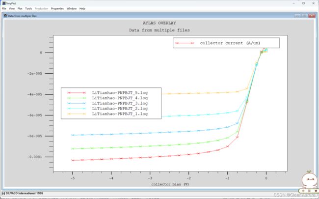
三、PNP型三极管共射极输出特性曲线:
四、特性分析:
由图可知,PNP型三极管基极导通电压Vbe约为-0.1V。三极管工作在放大状态时Vbe约为-0.1V到-0.5V之间。同时从输出特性曲线可知,当管子饱和时,饱和管压降较小,Vces 约为-0.6V。它与NPN 型硅三极管相比,不仅电压、电流方向不同,而且导通电压数值较小。利用这些特点,可以很容易地在电路中区分出PNP型三极管。
五、实验程序与详细注释:
go athena

#定义网格

line x loc=0.0         spacing=0.03

line x loc=0.2         spacing=0.02

line x loc=0.24        spacing=0.01

line x loc=0.3         spacing=0.015

line x loc=0.8         spacing=0.15


line y loc=0.0         spacing=0.01

line y loc=0.1         spacing=0.01

line y loc=0.4         spacing=0.02

line y loc=0.5         spacing=0.06

line y loc=1.0         spacing=0.15


#衬底掺杂硼,浓度为2e16

init c.boron=2e16


# 基区注入磷离子

implant   phos  energy=100 dose=8e13


# 基区退火

diffuse time=5 temp=900


# 淀积多晶硅栅厚度为0.3,设置10个网格

deposit poly thick=0.3 divisions=6 min.space=0.05


# 多晶掺杂 杂质为bf2 使用剂量为3e15 能量35kev

implant bf2 dose=3e15 energy=35


# 从x=0.2um到右边的多晶硅被刻蚀

etch poly right p1.x=0.2


# 放宽网格

relax y.min=.5

relax x.min=0.4


# 发射区退火

method compress fermi

diffuse time=45   temp=900 nitrogen


# 发射区离子注入

implant phos dose=2e14 energy=70


# 沉积氧化层

deposit oxide thick=0.3 divisions=10  min.space=0.1


# 刻蚀氧化层

etch oxide dry thick=0.3


# N型离子重掺杂后进行接触区退火

implant arsenic dose=1e15 energy=50

diffuse time=30 temp=900   nitrogen


# 在接触区淀积铝之后反刻铝

deposit alum thick=0.05 div=2

etch alum start x=0.16 y=-4

etch continue x=0.16 y=0.2

etch continue x=0.6 y=0.2

etch done  x=0.6 y=-4


# 命名电极

electrode x=0.0    name=emitter

electrode x=0.7    name=base

electrode backside name=collector


# 提取结深

extract name="EB_xj" xj material="Silicon" mat.occno=1 x.val=0.1 junc.occno=1

extract name="BC_xj" xj material="Silicon" mat.occno=1 x.val=0.1 junc.occno=2

extract name="base_width" $BC_xj - $EB_xj


#提取一维电气参数

extract name="base_rho" n.sheet.res material="Silicon" mat.occno=1 x.val=0.1 region.occno=2 extract name="poly_emitter_rho" p.sheet.res material="Polysilicon" mat.occno=1 x.val=0.1 region.occno=1 semi.poly


#保存最终结构在LiTianhao-PNPBJT.str中

structure outfile=LiTianhao-PNPBJT.str

tonyplot  LiTianhao-PNPBJT.str


#接下来进行器件特性模拟

#Gummel Plot 测试

go atlas


# 设置材料和模型参数

material material=Polysilicon taun0=1e-9 taup0=1e-9 mun=40 mup=2

material material=Silicon     taun0=5e-6 taup0=5e-6

models

models material=Silicon bipolar print

models material=Polysilicon srh


 #提供零偏压下势能和载流子浓度初始值

solve init

method newton autonr trap

solve prev


#设置集电极电压,基极电压从-0.1到-0.4变化,-0.1步进

solve vcollector=-2

solve vbase=-0.1 vstep=-0.1 vfinal=-0.4 name=base

log outf=LiTianhao-PNPBJT_0.log

solve vbase=-0.4 vstep=-0.05 vfinal=-1.0 name=base ac freq=1e6 aname=base


# 提取各种参数

extract name="peak collector current" max(abs(i."collector"))

extract name="peak gain" max(i."collector"/ i."base")

extract name="max fT" max(g."collector""base"/(2*3.1415*c."base""base"))

tonyplot  LiTianhao-PNPBJT_0.log


# IC/VCE (输出特性曲线)测试

go atlas

material material=Polysilicon taun0=1e-9 taup0=1e-9 mun=40 mup=2

material material=Silicon     taun0=5e-6 taup0=5e-6

models

models material=Silicon bipolar print

models material=Polysilicon srh


solve init

solve vbase=-0.025

solve vbase=-0.05

solve  vbase=-0.1 vstep=-0.1 vfinal=-0.7 name=base


# 设置边界条件

contact name=base current


# 保存基极偏置电流的恒定初始值

solve ibase=-1.e-6 outf=LiTianhao-PNPBJT_1.str master

solve ibase=-2.e-6 outf=LiTianhao-PNPBJT_2.str master

solve ibase=-3.e-6 outf=LiTianhao-PNPBJT_3.str master

solve ibase=-4.e-6 outf=LiTianhao-PNPBJT_4.str master

solve ibase=-5.e-6 outf=LiTianhao-PNPBJT_5.str master


# 加载到每个初始基极电流文件和步进 VCE

load inf=LiTianhao-PNPBJT_1.str master

log outf=LiTianhao-PNPBJT_1.log

solve vcollector=0.0 vstep=-0.25 vfinal=-5.0 name=collector


load inf=LiTianhao-PNPBJT_2.str master

log outf=LiTianhao-PNPBJT_2.log

solve vcollector=0.0 vstep=-0.25 vfinal=-5.0 name=collector


load inf=LiTianhao-PNPBJT_3.str master

log outf=LiTianhao-PNPBJT_3.log

solve vcollector=0.0 vstep=-0.25 vfinal=-5.0 name=collector


load inf=LiTianhao-PNPBJT_4.str master

log outf=LiTianhao-PNPBJT_4.log

solve vcollector=0.0 vstep=-0.25 vfinal=-5.0 name=collector


load inf=LiTianhao-PNPBJT_5.str master

log outf=LiTianhao-PNPBJT_5.log

solve vcollector=0.0 vstep=-0.25 vfinal=-5.0 name=collector


# 提取峰值电流和β值

extract name="pnp_max_ic_mA" max(abs(i."collector"))*1.0e+3

extract name="pnp_lin_slope" slope(maxslope(curve(v."collector",i."collector")))

extract name="pnp_sat_slope" slope(minslope(curve(v."collector",i."collector")))

tonyplot -overlay LiTianhao-PNPBJT_5.log LiTianhao-PNPBJT_4.log LiTianhao-PNPBJT_3.log LiTianhao-PNPBJT_2.log LiTianhao-PNPBJT_1.log


quit
**第二步:**使用SILVACO软件设计一个NPN管,进行相应的工艺模拟与器件模拟,要求输出Gummel曲线及IC——VCE特性曲线,并调整相关参数,观察并分析各关键工艺步骤对晶体管性能的影响。
四、特性分析:
由图可知,当Ib改变时,Ic和Vce的关系是一组平行的曲线族,并有截止、放大、饱和三个工作区。
1、截止区:此时晶体管的集电结处于反偏,发射结电压Vbe<0处于反偏,由于Ib=0,在反向饱和电流可忽略的前提下,Ic=βIb也等于0,晶体管无电流的放大作用。
2、放大区:工作在放大区的三极管有电流的放大作用,此时三极管的发射结正偏,集电结反偏,由输出特性曲线可见,当Ib等量变化时,Ic几乎也按一定比例等距离平行变化,此时三极管可近似看做一个输出电流Ic受Ib控制的受控电流源。
3、饱和区:当集电极电流Ic增大时,Vce=Vcc-Rc将下降,对于硅管,当Vce 降低到小于0.7V时,集电结进入正向偏置的状态,集电极吸引电子的能力将下降,此时即使Ib再增大,Ic也几乎不再增大了,三极管失去了电流放大作用。这种状态下,三极管为饱和状态。
通过上述两个选做题的实践与分析可看出,NPN型三极管的输出特性曲线和PNP型三极管的输出特性曲线是一组关于原点对称的图象。它们电压、电流方向不同,而且PNP三极管导通电压数值较小,利用这些特点可以实现特殊要求的电路。
五、实验程序与详细注释:
go atlas


# 建立网格

mesh

x.m l=0  spacing=0.15

x.m l=0.8 spacing=0.15

x.m l=1.0 spacing=0.03

x.m l=1.5 spacing=0.12

x.m l=2.0 spacing=0.15


y.m l=0.0  spacing=0.006

y.m l=0.04 spacing=0.006

y.m l=0.06 spacing=0.005

y.m l=0.15 spacing=0.02

y.m l=0.30 spacing=0.02

y.m l=1.0  spacing=0.12


#定义发射区,集电区,基区三个区域,同时分析代码:欧姆区掺杂(因为电极还要做重掺杂才可以做成欧姆接触,所以做欧姆接触需要掺杂)

region num=1 silicon


electrode num=1 name=emitter left length=0.8

electrode num=2 name=base    right length=0.5 y.max=0

electrode num=3 name=collector bottom


#掺杂:高斯分布(离子注入时均匀掺杂突变结,实际情况是缓变结。)

doping reg=1 uniform n.type conc=5e15

doping reg=1 gauss   n.type conc=1e18 peak=1.0 char=0.2

doping reg=1 gauss   p.type conc=1e18 peak=0.05 junct=0.15

doping reg=1 gauss   n.type conc=5e19 peak=0.0  junct=0.05 x.right=0.8

doping reg=1 gauss   p.type conc=5e19 peak=0.0  char=0.08 x.left=1.5


#工艺仿真器件制作完成,保存到我的LiTianhao-BJT_athena.str文件中

save outf=LiTianhao-BJT_athena.str

tonyplot  LiTianhao-BJT_athena.str


#接下来进行器件特性仿真:

models conmob fldmob consrh auger print

contact name=emitter n.poly surf.rec


# Gummel plot仿真

solve init

method  newton autonr trap

solve vcollector=0.025

solve vcollector=0.1

solve vcollector=0.25 vstep=0.25 vfinal=2 name=collector


solve vbase=0.025

solve vbase=0.1

solve vbase=0.2


log outf= LiTianhao-BJT_0.log

solve vbase=0.3 vstep=0.05 vfinal=1 name=base


tonyplot   LiTianhao-BJT_0.log


#IC/VCE仿真,此时基极电流恒定

#偏置基极

log off


solve init

solve vbase=0.025

solve vbase=0.05


solve  vbase=0.1 vstep=0.1 vfinal=0.7 name=base


#定义基极为电流边界

contact name=base current


#将基极偏置到不同的电流值

solve ibase=1.e-6

save outf=LiTianhao-BJT_1.str master

solve ibase=2.e-6

save outf=LiTianhao-BJT_2.str master

solve ibase=3.e-6

save outf=LiTianhao-BJT_3.str master

solve ibase=4.e-6

save outf=LiTianhao-BJT_4.str master

solve ibase=5.e-6

save outf=LiTianhao-BJT_5.str master


#载入不同基极电流,偏置集电极

load inf=LiTianhao-BJT_1.str master

log outf=LiTianhao-BJT_1.log

solve vcollector=0.0 vstep=0.25 vfinal=5.0 name=collector


load inf=LiTianhao-BJT_2.str master

log outf=LiTianhao-BJT_2.log

solve vcollector=0.0 vstep=0.25 vfinal=5.0 name=collector


load inf=LiTianhao-BJT_3.str master

log outf=LiTianhao-BJT_3.log

solve vcollector=0.0 vstep=0.25 vfinal=5.0 name=collector


load inf=LiTianhao-BJT_4.str master

log outf=LiTianhao-BJT_4.log

solve vcollector=0.0 vstep=0.25 vfinal=5.0 name=collector


load inf=LiTianhao-BJT_5.str master

log outf=LiTianhao-BJT_5.log

solve vcollector=0.0 vstep=0.25 vfinal=5.0 name=collector


#输出曲线族

tonyplot -overlay  LiTianhao-BJT_1.log LiTianhao-BJT_2.log LiTianhao-BJT_3.log LiTianhao-BJT_4.log LiTianhao-BJT_5.log


quit


