三层架构实验
三层架构实验要求图
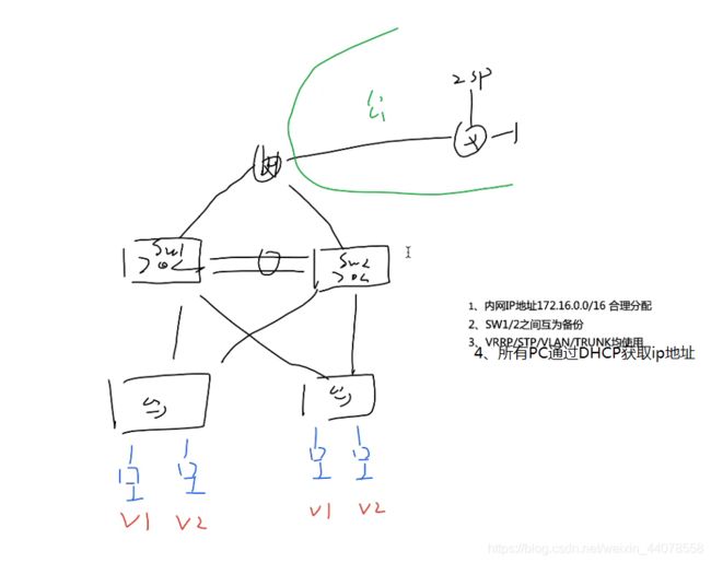
实验要求
1.内部IP地址172.16.0.0/16合理分配
2.sw1和sw2之间互为备份
3.vrrp/stp/vlan/trunk均使用
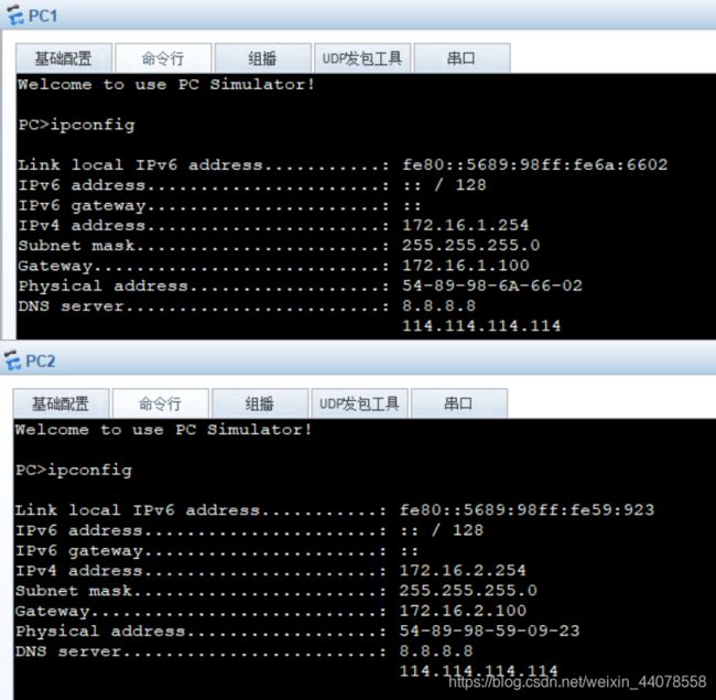
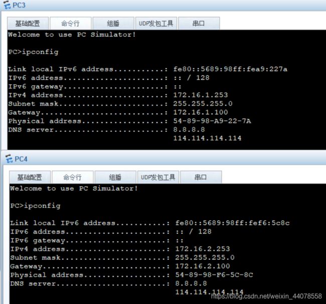
4.所有pc通过dhcp获取IP地址
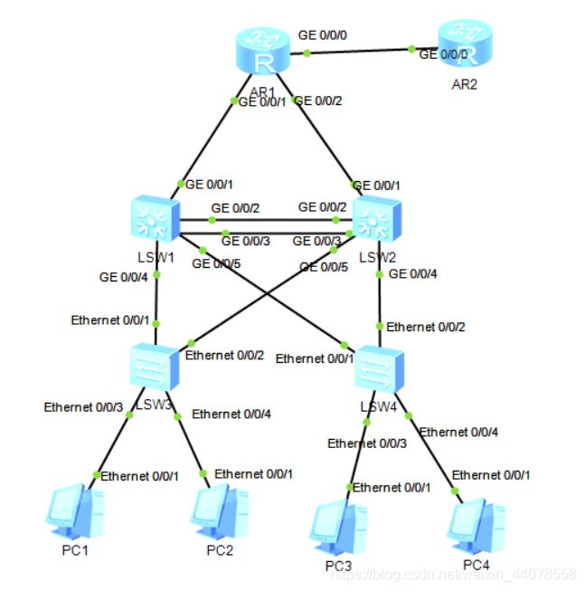
拓扑图
划分地址
172.16.0.0/16
路由部分地址
172.16.0.0/30
172.16.0.4/30
两个地址池网段
172.16.1.0/24
172.16.2.0/24
实验分析
交换部分
1.eth-trunk 2.vlan 3.trunk 4.stp 5.svi
6.vrrp 7.dhcp
路由部分
配置地址 路由协议 测试 acl nat
配置
交换部分
1.在sw1和sw2上做eth-trunk
[sw1]interface Eth-Trunk 1
[sw1-Eth-Trunk1]q
[sw1]interface g0/0/2
[sw1-GigabitEthernet0/0/2]eth-trunk 1
[sw1-GigabitEthernet0/0/2]q
[sw1]interface g0/0/3
[sw1-GigabitEthernet0/0/3]eth-trunk 1
[sw2]interface Eth-Trunk 1
[sw2-Eth-Trunk1]q
[sw2]interface g0/0/2
[sw2-GigabitEthernet0/0/2]eth-trunk 1
[sw2-GigabitEthernet0/0/2]q
[sw2]interface g0/0/3
[sw2-GigabitEthernet0/0/3]eth-trunk 1
2.配置vlan和trunk
[sw1]vlan 2
[sw1-vlan2]
[sw1-vlan2]q
[sw1]interface Eth-Trunk 1
[sw1-Eth-Trunk1]port link-type trunk
[sw1-Eth-Trunk1]port trunk allow-pass vlan all
[sw1-Eth-Trunk1]int g0/0/4
[sw1-GigabitEthernet0/0/4]port link-type trunk
[sw1-GigabitEthernet0/0/4]port trunk allow-pass vlan all
[sw1-GigabitEthernet0/0/4]int g0/0/5
[sw1-GigabitEthernet0/0/5]port link-type trunk
[sw1-GigabitEthernet0/0/5]port trunk allow-pass vlan all
[sw2]vlan 2
[sw2-vlan2]
[sw2-vlan2]q
[sw2]interface Eth-Trunk 1
[sw2-Eth-Trunk1]port link-type trunk
[sw2-Eth-Trunk1]port trunk allow-pass vlan all
[sw2-Eth-Trunk1]int g0/0/4
[sw2-GigabitEthernet0/0/4]port link-type trunk
[sw2-GigabitEthernet0/0/4]port trunk allow-pass vlan all
[sw2-GigabitEthernet0/0/4]int g0/0/5
[sw2-GigabitEthernet0/0/5]port link-type trunk
[sw2-GigabitEthernet0/0/5]port trunk allow-pass vlan all
[sw3]vlan 2
[sw3-vlan2]
[sw3-vlan2]q
[sw3]interface Ethernet0/0/1
[sw3-Ethernet0/0/1]port link-type trunk
[sw3-Ethernet0/0/1]port trunk allow-pass vlan all
[sw3-Ethernet0/0/1]int e0/0/2
[sw3-Ethernet0/0/2]port link-type trunk
[sw3-Ethernet0/0/2]port trunk allow-pass vlan all
[sw4]vlan 2
[sw4-vlan2]
[sw4-vlan2]q
[sw4]interface e0/0/1
[sw4-Ethernet0/0/1]port link-type trunk
[sw4-Ethernet0/0/1]port trunk allow-pass vlan all
[sw4-Ethernet0/0/1]int e0/0/2
[sw4-Ethernet0/0/2]port link-type trunk
[sw4-Ethernet0/0/2]port trunk allow-pass vlan all
在sw3和sw4上配置向下的接口
[sw3]interface e0/0/3
[sw3-Ethernet0/0/3]port link-type access
[sw3-Ethernet0/0/3]port default vlan 1
[sw3-Ethernet0/0/3]int e0/0/4
[sw3-Ethernet0/0/4]port link-type access
[sw3-Ethernet0/0/4]port default vlan 2
[sw4]int e0/0/3
[sw4-Ethernet0/0/3]port link-type access
[sw4-Ethernet0/0/3]port default vlan 1
[sw4-Ethernet0/0/3]int e0/0/4
[sw4-Ethernet0/0/4]port link-type access
[sw4-Ethernet0/0/4]port default vlan 2
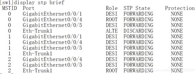
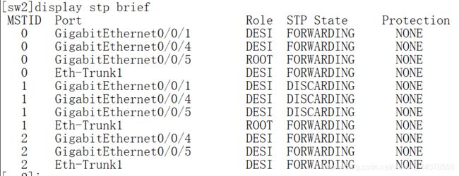
3.配置stp
[sw1]stp enable
[sw1]stp mode mstp
[sw1]stp region-configuration
[sw1-mst-region]region-name openlab
[sw1-mst-region]instance 1 vlan 1
[sw1-mst-region]instance 2 vlan 2
[sw1-mst-region]active region-configuration
[sw2]stp enable
[sw2]stp mode mstp
[sw2]stp region-configuration
[sw2-mst-region]region-name openlab
[sw2-mst-region]instance 1 vlan 1
[sw2-mst-region]instance 2 vlan 2
[sw2-mst-region]active region-configuration
[sw3]stp enable
[sw3]stp mode mstp
[sw3]stp region-configuration
[sw3-mst-region]region-name openlab
[sw3-mst-region]instance 1 vlan 1
[sw3-mst-region]instance 2 vlan 2
[sw3-mst-region]active region-configuration
[sw4]stp enable
[sw4]stp mode mstp
[sw4]stp region-configuration
[sw4-mst-region]region-name openlab
[sw4-mst-region]instance 1 vlan 1
[sw4-mst-region]instance 2 vlan 2
[sw4-mst-region]active region-configuration
在sw1和sw2上设置根端口
[sw1]stp instance 1 root primary
[sw1]stp instance 2 root secondary
[sw2]stp instance 1 root secondary
[sw2]stp instance 2 root primary
在sw3和sw4上向下的接口设置不参与生成树选举
[sw3]interface e0/0/3
[sw3-Ethernet0/0/3]stp edged-port enable
[sw3-Ethernet0/0/3]interface e0/0/4
[sw3-Ethernet0/0/4]stp edged-port enable
[sw4]int e0/0/3
[sw4-Ethernet0/0/3]stp edged-port enable
[sw4-Ethernet0/0/3]int e0/0/4
[sw4-Ethernet0/0/4]stp edged-port enable
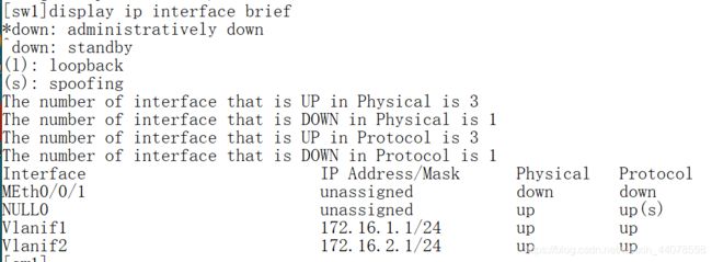
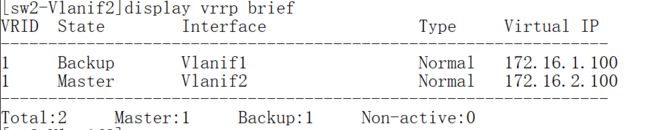
4.配置svi及vrrp
[sw1]interface Vlanif 1
[sw1-Vlanif1]ip address 172.16.1.1 24
[sw1-Vlanif1]q
[sw1]interface Vlanif 2
[sw1-Vlanif2]ip address 172.16.2.1 24
[sw1]interface Vlanif 1
[sw1-Vlanif1]vrrp vrid 1 virtual-ip 172.16.1.100
[sw1-Vlanif1]vrrp vrid 1 priority 101
[sw1-Vlanif1]vrrp vrid 1 track interface GigabitEthernet 0/0/1
[sw1-Vlanif1]int vl 2
[sw1-Vlanif2]vrrp vrid 1 virtual-ip 172.16.2.100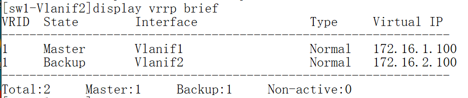
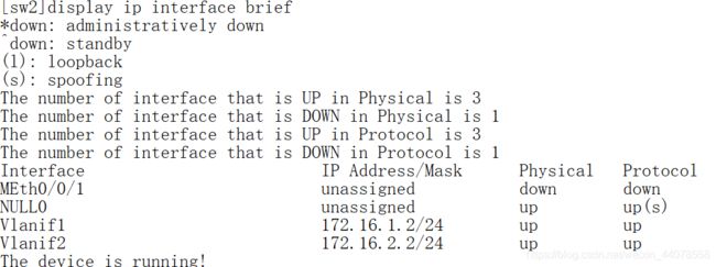
[sw2]interface Vlanif 1
[sw2-Vlanif1]ip address 172.16.1.2 24
[sw2-Vlanif1]q
[sw2]interface Vlanif 2
[sw2-Vlanif2]ip address 172.16.2.2 24
[sw2]interface Vlanif 1
[sw2-Vlanif1]vrrp vrid 1 virtual-ip 172.16.1.100
[sw2-Vlanif1]q
[sw2]interface Vlanif 2
[sw2-Vlanif2]vrrp vrid 1 virtual-ip 172.16.2.100
[sw2-Vlanif2]vrrp vrid 1 priority 101
[sw2-Vlanif2]vrrp vrid 1 track interface g0/0/1
5.配置dhcp
[sw1]dhcp enable
[sw1]ip pool 1
[sw1-ip-pool-1]gateway-list 172.16.1.100
[sw1-ip-pool-1]network 172.16.1.0 mask 24
[sw1-ip-pool-1]dns-list 8.8.8.8 114.114.114.114
[sw1-ip-pool-1]q
[sw1]ip pool 2
[sw1-ip-pool-2]gateway-list 172.16.2.100
[sw1-ip-pool-2]network 172.16.2.0 mask 24
[sw1-ip-pool-2]dns-list 8.8.8.8 114.114.114.114
[sw1-ip-pool-2]q
[sw1]interface Vlanif 1
[sw1-Vlanif1]dhcp select global
[sw1-Vlanif1]interface vl 2
[sw1-Vlanif2]dhcp select global
[sw2]dhcp enable
[sw2]ip pool 1
[sw2-ip-pool-1]gateway-list 172.16.1.100
[sw2-ip-pool-1]network 172.16.1.0 mask 24
[sw2-ip-pool-1]dns-list 8.8.8.8 114.114.114.114
[sw2-ip-pool-1]q
[sw2]ip pool 2
[sw2-ip-pool-2]gateway-list 172.16.2.100
[sw2-ip-pool-2]network 172.16.2.0 mask 24
[sw2-ip-pool-2]dns-list 8.8.8.8 114.114.114.114
[sw2-ip-pool-2]q
[sw2]int v 1
[sw2-Vlanif1]dhcp select global
[sw2-Vlanif1]int v 2
[sw2-Vlanif2]dhcp select global
路由部分
1.配置地址
[r1]interface g0/0/1
[r1-GigabitEthernet0/0/1]ip address 172.16.0.2 30
[r1-GigabitEthernet0/0/1]int g0/0/2
[r1-GigabitEthernet0/0/2]ip address 172.16.0.6 30
[r1-GigabitEthernet0/0/2]int g0/0/0
[r1-GigabitEthernet0/0/0]ip address 12.1.1.1 24
[r2]interface g0/0/0
[r2-GigabitEthernet0/0/0]ip address 12.1.1.2 24
[r2-GigabitEthernet0/0/0]q
[r2]int LoopBack 0
[r2-LoopBack0]ip address 1.1.1.1 24
[sw1]vlan 3
[sw1-vlan3]int v 3
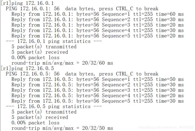
[sw1-Vlanif3]ip address 172.16.0.1 30
[sw1-Vlanif3]q
[sw1]interface g0/0/1
[sw1-GigabitEthernet0/0/1]port link-type access
[sw1-GigabitEthernet0/0/1]port default vlan 3
[sw2]vlan 4
[sw2-vlan4]q
[sw2]int Vlanif 4
[sw2-Vlanif4]ip address 172.16.0.5 30
[sw2-Vlanif4]q
[sw2]int g0/0/1
[sw2-GigabitEthernet0/0/1]port link-type access
[sw2-GigabitEthernet0/0/1]port default vlan 4
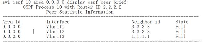
2.配置ospf
[r1]ospf 10 router-id 1.1.1.1
[r1-ospf-10]area 0
[r1-ospf-10-area-0.0.0.0]network 172.16.0.0 0.0.255.255
[sw1]ospf 10 router-id 2.2.2.2
[sw1-ospf-10]area 0
[sw1-ospf-10-area-0.0.0.0]network 172.16.0.0 0.0.255.255
[sw2]ospf 10 router-id 3.3.3.3
[sw2-ospf-10]area 0
[sw2-ospf-10-area-0.0.0.0]network 172.16.0.0 0.0.255.255
优化 禁止Vlanif 2发送ospf报文 同时禁止向下的接口发送ospf报文
[sw1-ospf-10]silent-interface Vlanif 2
[sw1-ospf-10]silent-interface g0/0/4
[sw1-ospf-10]silent-interface g0/0/5
[sw2-ospf-10]silent-interface g0/0/4
[sw2-ospf-10]silent-interface g0/0/5
在r1上配置静态缺省
[r1]ip route-static 0.0.0.0 0.0.0.0 12.1.1.2
将静态重发布到ospf域中
[r1]ospf 10
[r1-ospf-10]default-route-advertise

3.要访问isp,在r1上配置acl和nat
[r1]acl 2000
[r1-acl-basic-2000]rule 0 permit source 172.16.0.0 0.0.255.255
[r1-acl-basic-2000]q
[r1]interface g0/0/0
[r1-GigabitEthernet0/0/0]nat outbound 2000
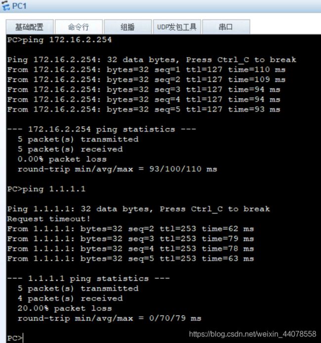
测试