动态路由之RIP协议(思科)
路由协议分类:
内部网关协议
外部网关协议
路由协议的作用:
发现远程网络
维护最新路由信息
选择通往目标网络的最佳路径
当前路径无法使用时找出新的最佳路径
动态路由协议的主要要素:
数据结构
路由协议消息
算法
静态路由一般用在末节网络
配置rip协议
1、开启rip配置
全局配置模式下router rip
2、检验rip设置和路由
特权模式下 show ip protocols
特权模式下 show ip route
3、启用ripv2
config-router下version 2
4、禁用自动汇总
no auto-summary
5、配置被动接口
config-router下:passive-interface g0/0
6、传播默认路由
全局配置模式下:ip route 0.0.0.0 0.0.0.0 s0/0/1 202.206.79.1
config-router下:default-information originate
7、配置rip
config-router下:network ip地址
____正片开始____
________
_____
_
一、搭建拓扑如下
二、实验要求
目标
第 1 部分:配置 RIPv2
第 2 部分:验证配置
背景信息
尽管在现代网络中极少使用 RIP,但是作为了解基本网络路由的基础则十分有用。 在本活动中,您将使用适当的网络语句和被动接口配置默认路由(RIP 版本 2),并验证全连接。
第 1 部分: 配置 RIPv2
步骤 1: 在 R1 上配置 RIPv2。
a. 使用适当的命令在 R1 上创建默认路由,以使所有互联网流量通过 S0/0/1 离开网络。
b. 进入 RIP 协议配置模式。
c. 使用 RIP 协议的第 2 版并禁用网络汇总。
d. 为连接到 R1 的网络配置 RIP。
e. 配置不含路由器的 LAN 端口,这样端口就不会发出任何路由信息。
f. 通过其他 RIP 路由器,通告步骤 1a 中配置的默认路由。
g. 保存配置。
步骤 2: 在 R2 上配置 RIPv2。
a. 输入 RIP 协议配置模式。
b. 使用 RIP 协议的第 2 版并禁用网络汇总。
c. 为直接连接到 R2 的网络配置 RIP。
d. 配置不包含路由器的接口,以使其不发送路由信息。
e. 保存配置。
步骤 3: 在 R3 上配置 RIPv2
在 R3 上重复执行步骤 2。
第 2 部分: 验证配置
步骤 1: 查看 R1、R2 和 R3 的路由表。
a. 使用适当的命令显示 R1 的路由表。 此时,路由表中会显示 RIP ® 以及连接的路由 © 和本地 (L) 路由。 所有网络都有一个条目。 您还会看到列出了一个默认路由。
b. 查看 R2 和 R3 的路由表。 请注意,每个路由器都有所有 192.168.x.0 网络的完整列表和一个默认路由。
步骤 2: 检验与所有目的地的完全连接。
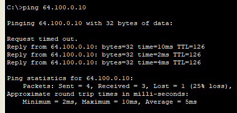
此时,每个设备都应能够 ping 网络内的每一个其他设备。 此外,所有设备都应能够 ping Web 服务器。
三、实现
第一部分
步骤 1: 在 R1 上配置 RIPv2。
a. 使用适当的命令在 R1 上创建默认路由,以使所有互联网流量通过 S0/0/1 离开网络。
R1(config)#ip route 0.0.0.0 0.0.0.0 s0/0/1
b. 进入 RIP 协议配置模式。
R1(config)# router rip
c. 使用 RIP 协议的第 2 版并禁用网络汇总。
R1(config-router)#version 2
R1(config-router)#no auto-summary
d. 为连接到 R1 的网络配置 RIP。
R1(config-router)#network 192.168.1.0
R1(config-router)#network 192.168.2.0
e. 配置不含路由器的 LAN 端口,这样端口就不会发出任何路由信息。
R1(config-router)#passive-interface g0/0
f. 通告其他 RIP 路由器,通告内容为步骤 1a 中配置的默认路由。
R1(config-router)#default-information originate
g. 保存配置。
R1#wr
Building configuration...
[OK]
步骤 2: 在 R2 上配置 RIPv2。
a. 输入 RIP 协议配置模式。
R2(config)#route rip
b. 使用 RIP 协议的第 2 版并禁用网络汇总。
R2(config-router)#version 2
R2(config-router)#no auto-summary
c. 为直接连接到 R2 的网络配置 RIP。
R2(config-router)#network 192.168.2.0
R2(config-router)#network 192.168.3.0
R2(config-router)#network 192.168.4.0
d. 配置不包含路由器的接口,以使其不发送路由信息。
R2(config-router)#passive-interface g0/0
e. 保存配置。
R2#wr
Building configuration...
[OK]
R2#
步骤 3: 在 R3 上配置 RIPv2
在 R3 上重复执行步骤 2。
第二部分
步骤 1: 查看 R1、R2 和 R3 的路由表。
R1
R1#show ip route
Codes: L - local, C - connected, S - static, R - RIP, M - mobile, B - BGP
       D - EIGRP, EX - EIGRP external, O - OSPF, IA - OSPF inter area
       N1 - OSPF NSSA external type 1, N2 - OSPF NSSA external type 2
       E1 - OSPF external type 1, E2 - OSPF external type 2, E - EGP
       i - IS-IS, L1 - IS-IS level-1, L2 - IS-IS level-2, ia - IS-IS inter area
       * - candidate default, U - per-user static route, o - ODR
       P - periodic downloaded static route

Gateway of last resort is 0.0.0.0 to network 0.0.0.0

     192.168.1.0/24 is variably subnetted, 2 subnets, 2 masks
C       192.168.1.0/24 is directly connected, GigabitEthernet0/0
L       192.168.1.1/32 is directly connected, GigabitEthernet0/0
     192.168.2.0/24 is variably subnetted, 2 subnets, 2 masks
C       192.168.2.0/24 is directly connected, Serial0/0/0
L       192.168.2.1/32 is directly connected, Serial0/0/0
R    192.168.3.0/24 [120/1] via 192.168.2.2, 00:00:16, Serial0/0/0
R    192.168.4.0/24 [120/1] via 192.168.2.2, 00:00:16, Serial0/0/0
R    192.168.5.0/24 [120/2] via 192.168.2.2, 00:00:16, Serial0/0/0
     209.165.200.0/24 is variably subnetted, 2 subnets, 2 masks
C       209.165.200.224/30 is directly connected, Serial0/0/1
L       209.165.200.225/32 is directly connected, Serial0/0/1
S*   0.0.0.0/0 is directly connected, Serial0/0/1
R2
R2#show ip route
Codes: L - local, C - connected, S - static, R - RIP, M - mobile, B - BGP
       D - EIGRP, EX - EIGRP external, O - OSPF, IA - OSPF inter area
       N1 - OSPF NSSA external type 1, N2 - OSPF NSSA external type 2
       E1 - OSPF external type 1, E2 - OSPF external type 2, E - EGP
       i - IS-IS, L1 - IS-IS level-1, L2 - IS-IS level-2, ia - IS-IS inter area
       * - candidate default, U - per-user static route, o - ODR
       P - periodic downloaded static route

Gateway of last resort is 192.168.2.1 to network 0.0.0.0

R    192.168.1.0/24 [120/1] via 192.168.2.1, 00:00:05, Serial0/0/0
     192.168.2.0/24 is variably subnetted, 2 subnets, 2 masks
C       192.168.2.0/24 is directly connected, Serial0/0/0
L       192.168.2.2/32 is directly connected, Serial0/0/0
     192.168.3.0/24 is variably subnetted, 2 subnets, 2 masks
C       192.168.3.0/24 is directly connected, GigabitEthernet0/0
L       192.168.3.1/32 is directly connected, GigabitEthernet0/0
     192.168.4.0/24 is variably subnetted, 2 subnets, 2 masks
C       192.168.4.0/24 is directly connected, Serial0/0/1
L       192.168.4.2/32 is directly connected, Serial0/0/1
R    192.168.5.0/24 [120/1] via 192.168.4.1, 00:00:22, Serial0/0/1
R*   0.0.0.0/0 [120/1] via 192.168.2.1, 00:00:05, Serial0/0/0
R3
R3(config)#do show ip route
Codes: L - local, C - connected, S - static, R - RIP, M - mobile, B - BGP
       D - EIGRP, EX - EIGRP external, O - OSPF, IA - OSPF inter area
       N1 - OSPF NSSA external type 1, N2 - OSPF NSSA external type 2
       E1 - OSPF external type 1, E2 - OSPF external type 2, E - EGP
       i - IS-IS, L1 - IS-IS level-1, L2 - IS-IS level-2, ia - IS-IS inter area
       * - candidate default, U - per-user static route, o - ODR
       P - periodic downloaded static route

Gateway of last resort is 192.168.4.2 to network 0.0.0.0

R    192.168.1.0/24 [120/2] via 192.168.4.2, 00:00:06, Serial0/0/1
R    192.168.2.0/24 [120/1] via 192.168.4.2, 00:00:06, Serial0/0/1
R    192.168.3.0/24 [120/1] via 192.168.4.2, 00:00:06, Serial0/0/1
     192.168.4.0/24 is variably subnetted, 2 subnets, 2 masks
C       192.168.4.0/24 is directly connected, Serial0/0/1
L       192.168.4.1/32 is directly connected, Serial0/0/1
     192.168.5.0/24 is variably subnetted, 2 subnets, 2 masks
C       192.168.5.0/24 is directly connected, GigabitEthernet0/0
L       192.168.5.1/32 is directly connected, GigabitEthernet0/0
R*   0.0.0.0/0 [120/2] via 192.168.4.2, 00:00:06, Serial0/0/1

R3(config)#
步骤 2: 检验与所有目的地的完全连接。
pc1 ping pc3
pc1 ping 服务器
192.168.5.0/24 is directly connected, GigabitEthernet0/0
L 192.168.5.1/32 is directly connected, GigabitEthernet0/0
R* 0.0.0.0/0 [120/2] via 192.168.4.2, 00:00:06, Serial0/0/1
R3(config)#
**步骤 2: 检验与所有目的地的完全连接。**
pc1 ping 服务器


