ROS相机内参标定详细步骤指南
作者: Herman Ye @Galbot @Auromix
版本: V1.0
测试环境: Ubuntu20.04 、ROS1 Noetic
更新日期: 2023/09/14
注1: 本文内容中的硬件由 @Galbot 提供支持。
注2: @Auromix 是一个机器人爱好者开源组织。
注3: 由于笔者水平有限,以下内容可能存在错误。
注4: 本文中直接引用各包官方文档的图片等内容,版权归各官方所有。
为什么要标定?
相机标定的目的是为了确定相机内部参数和外部参数,以便修正图像并将图像坐标映射到世界坐标,或者从世界坐标映射到图像坐标。这个过程是计算机视觉和三维感知任务的关键步骤之一,它有以下主要目的:
-
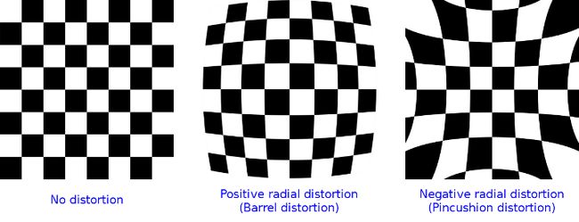
减小畸变:相机镜头和传感器可能引入径向和切向畸变,使得图像中的直线变得弯曲或者物体的形状不准确。通过标定相机,可以矫正这些畸变,使图像更准确。
-
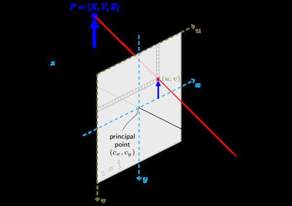
确定内部参数(intrinsic parameters):内部参数包括焦距、主点坐标和相机畸变参数。这些参数是描述相机如何捕捉世界的重要因素,它们的准确值对于计算深度、距离和姿态等任务至关重要,相机内参标定就是为了获取精确的内部参数。
distortion_model: "plumb_bob"
D: [0.0, 0.0, 0.0, 0.0, 0.0]
K: [911.4010620117188, 0.0, 645.8338623046875, 0.0, 910.145263671875, 347.9687194824219, 0.0, 0.0, 1.0]
P: [911.4010620117188, 0.0, 645.8338623046875, 0.0, 0.0, 910.145263671875, 347.9687194824219, 0.0, 0.0, 0.0, 1.0, 0.0]
- 确定外部参数:外部参数包括相机的位置和方向。这些参数描述了相机相对于世界坐标系的位置和朝向,允许将图像坐标映射到世界坐标,这对于机械臂的抓取很有帮助。
该篇不涉及外参标定,将在机械臂手眼标定的文章中讲解相机的外参标定。
        <!-- xyz="-0.162861 0.177661 -0.626113" rpy="1.45853 -2.03383 1.49474" -->
        <node pkg="tf2_ros" type="static_transform_publisher" name="camera_link_broadcaster"
            args="-0.162861 0.177661 -0.626113   -0.173987 -0.703383 -0.14907 0.672873 Link6 left_arm_camera_link" />
- 相机姿态估计:相机标定还可用于估计相机在拍摄图像时的姿态,即相机的旋转和平移。这对于虚拟现实、增强现实、机器人导航和定位等应用至关重要。
标定的原理[选看]
使用OpenCV标定
通过OpenCV进行相机标定的原理可以参考OpenCV相机校准和三维重建文档。
ros-noetic-camera-calibration
此处使用ros-noetic-camera-calibration工具包来方便地在ROS1 Noetic中标定相机。
camera_calibration包是一个允许使用棋盘格来轻松校准单目或立体相机的ROS包。
相机信息中的内参相关内容
以Intel Realsense彩色相机为例,以下是彩色相机的信息。
# rostopic echo /right_arm_camera/color/camera_info
---
header:
  seq: 32308
  stamp:
    secs: 1694683940
    nsecs: 530882359
  frame_id: "right_arm_camera_color_optical_frame"
height: 720
width: 1280
distortion_model: "plumb_bob"
D: [0.0, 0.0, 0.0, 0.0, 0.0]
K: [911.4010620117188, 0.0, 645.8338623046875, 0.0, 910.145263671875, 347.9687194824219, 0.0, 0.0, 1.0]
R: [1.0, 0.0, 0.0, 0.0, 1.0, 0.0, 0.0, 0.0, 1.0]
P: [911.4010620117188, 0.0, 645.8338623046875, 0.0, 0.0, 910.145263671875, 347.9687194824219, 0.0, 0.0, 0.0, 1.0, 0.0]
binning_x: 0
binning_y: 0
roi:
  x_offset: 0
  y_offset: 0
  height: 0
  width: 0
  do_rectify: False
---
header:
  seq: 32309
  stamp:
    secs: 1694683940
    nsecs: 564413071
  frame_id: "right_arm_camera_color_optical_frame"
height: 720
width: 1280
distortion_model: "plumb_bob"
D: [0.0, 0.0, 0.0, 0.0, 0.0]
K: [911.4010620117188, 0.0, 645.8338623046875, 0.0, 910.145263671875, 347.9687194824219, 0.0, 0.0, 1.0]
R: [1.0, 0.0, 0.0, 0.0, 1.0, 0.0, 0.0, 0.0, 1.0]
P: [911.4010620117188, 0.0, 645.8338623046875, 0.0, 0.0, 910.145263671875, 347.9687194824219, 0.0, 0.0, 0.0, 1.0, 0.0]
binning_x: 0
binning_y: 0
roi:
  x_offset: 0
  y_offset: 0
  height: 0
  width: 0
  do_rectify: False
---
其中包括相机的内部参数有关的参数:
当处理相机内参时,常见的三个参数是 D、K 和 P,此外相关的还有畸变模型。
D畸变系数(distortion_coefficients):D是一个通常包含五个元素的数组[k1, k2, p1, p2, k3],它用于描述相机图像中的径向和切向畸变。k1和k2是径向畸变系数,它们用于描述镜头的弯曲形状,通常是负数。p1和p2是切向畸变系数,它们用于描述镜头的畸变不对称性,通常是很小的值。k3是一个更高阶的径向畸变系数,通常情况下很小,有时甚至可以忽略。D用来表示径向和切向畸变。
D: [0.0, 0.0, 0.0, 0.0, 0.0]
K相机内参矩阵(camera_matrix):K是一个3x3的矩阵,它包括了相机的内部参数,用于将相机坐标系中的三维点映射到图像平面上的二维坐标。K的主要元素包括:K[0]和K[4]是焦距在图像 x 和 y 轴上的分量,通常以像素为单位。K[2]和K[5]是光心在图像 x 和 y 轴上的坐标,也以像素为单位。K[8]通常是1,是一个归一化参数。
K包含了焦距和主点的信息。
K: [911.4010620117188, 0.0, 645.8338623046875, 0.0, 910.145263671875, 347.9687194824219, 0.0, 0.0, 1.0]
P投影矩阵(projection_matrix):P是一个3x4的矩阵,它包含了相机的投影参数,用于将相机坐标系中的三维点映射到图像坐标系。P的元素包括了内参和外参信息。- 其中
P[0]和P[5]分别对应于焦距fx和fy,用于将相机坐标系的 x 和 y 坐标映射到图像坐标系上。 P[2]和P[6]对应于光心的 x 和 y 坐标cx和cy。P[3]和P[7]通常为0,用于表示没有视角的旋转或平移。P[10]通常是1,是一个归一化参数。- 投影矩阵
P包含了相机的内部参数和畸变参数。
P: [911.4010620117188, 0.0, 645.8338623046875, 0.0, 0.0, 910.145263671875, 347.9687194824219, 0.0, 0.0, 0.0, 1.0, 0.0]
distortion_model"(畸变模型):
distortion_model是相机标定信息中的一个字段,用于描述相机的畸变模型。
畸变模型是用来描述相机镜头产生的畸变效应的数学模型。
在计算机视觉中,畸变通常分为径向畸变和切向畸变两种主要类型,而畸变模型用于对这些畸变进行建模和校正。
Plumb Bob (钉形畸变模型):
- “plumb_bob” 畸变模型是最常见的畸变模型之一,也是默认的畸变模型。它通常用于描述径向畸变(Radial Distortion)和切向畸变(Tangential Distortion)。
- 径向畸变主要是由于镜头形状不完全圆形引起的,导致图像中心附近的像素与图像边缘的像素之间存在畸变。这种畸变通常用多项式函数建模。
- 切向畸变则是由于相机镜头不完全平行于图像平面引起的,导致图像中心附近的像素存在畸变。切向畸变通常也用多项式函数建模。
- “plumb_bob” 畸变模型使用径向和切向畸变系数(
D)来描述这两种畸变。
标定的材料
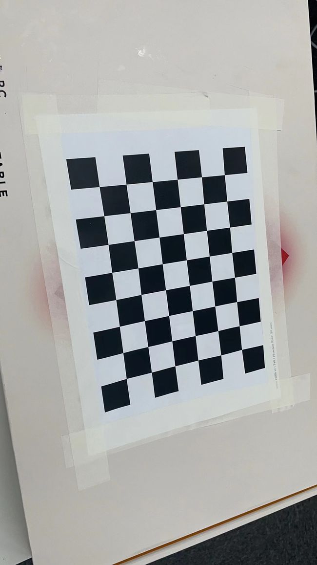
- 棋盘格:需要准备一个大小适中的黑白棋盘格,计算大小
8x6方格大小9X7的棋盘格是常见的选择,但请注意,内部角点的数量比较少的情况下,标定可能会不够精确。
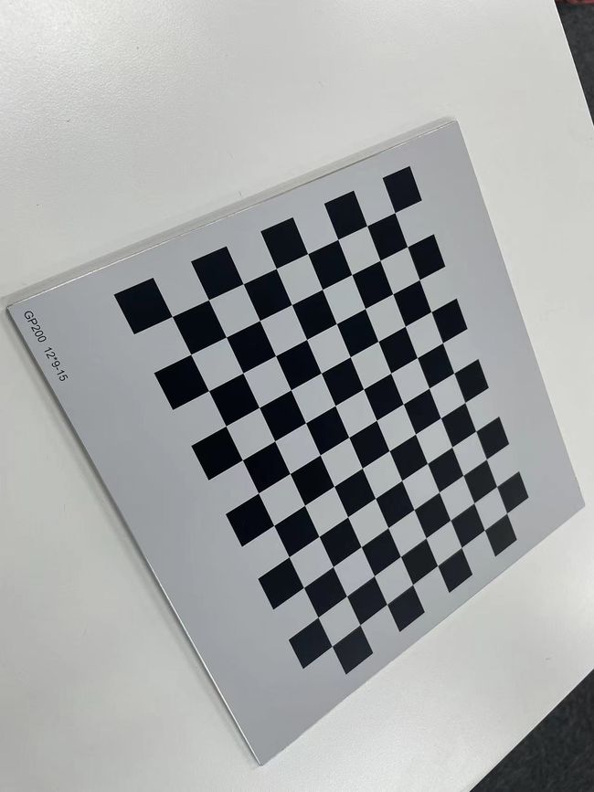
此处选用了计算大小11x8,方格大小12x9的铝基板黑白棋盘格,边长为15mm作为示例,这些制作好的标定板有更高的标定精度。
方格大小和计算大小是为了方便理解造的名词,将在之后解释。
如果手上没有标定板,也可以在线制作棋盘格并用A4纸打印出来,
推荐的参数如下:
| Name | Value |
|---|---|
| Target Type | Checkerboard |
| Board Width | 297 |
| Board Height | 210 |
| Rows(方格大小) | 7 |
| Columns(方格大小) | 9 |
| Checker Width [mm] | 25 |
注意事项:需要明确的是,棋盘格的计算大小是指内部角点的数量,按照OpenCV文档的描述,例如 计算大小 8x6 棋盘格实际上包含 9x7 个物理方格,也就是方格大小为9X7。
如图所示,数内部角点(图上红圈处)只有八个,也就是计算行大小为8,实际上的行方格数为9。
-
良好的光照条件:确保拍摄相机标定图像的区域光线充足,并且没有遮挡物或其他棋盘格图案。
-
相机:需要标定的相机,已接入ROS1 Noetic,并且使用了
rostopic获取相机发布的图像话题。
相机需要满足的需求:
- image_pipeline的硬件需求
- camera_driver的硬件需求
同时,相机硬件需要提供适用于ROS的节点,以便能够发布必要的图像话题。
开始标定
单目RGB相机(monocular)
此处以right_arm_camera为例:
- 1.下载
ros-noetic-camera-calibration
sudo apt install ros-noetic-camera-calibration -y
- 2.修改参数为需要校准的相机的参数
需要获取的参数如下:
| 参数 | 参考值 | 解释 |
|---|---|---|
| –size | 8x6 | 棋盘格计算大小8行x6列 |
| –square | 0.025 | 棋盘格方格的边长大小0.025米(25mm) |
| image:= | /right_arm_camera/color/image_raw | 名为right_arm_camera的相机的彩色相机图像话题 |
| camera:= | /right_arm_camera | 名为right_arm_camera相机 |
参数解释请参考camera_calibration文档。
- 3.运行校准程序
rosrun camera_calibration cameracalibrator.py --size 8x6 --square 0.025 image:=/right_arm_camera/color/image_raw camera:=/right_arm_camera
注意:因为校准工具会查找相机节点的set_camera_info服务,如果无法正确启动,添加以下参数到命令中
--no-service-check
- 3.调整标定板
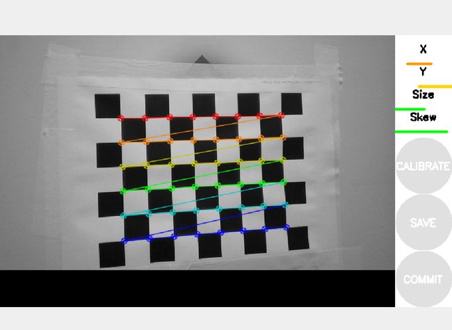
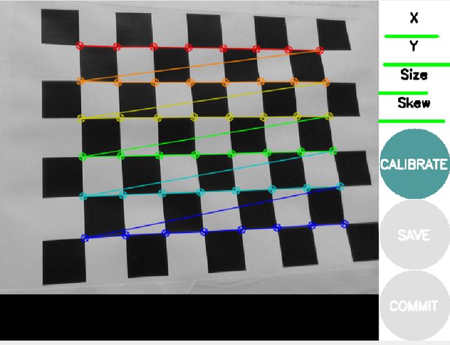
按照以下顺序调整标定板,使得相机拍摄尽量多的不同视角下的有效照片:
- 前后移动标定板
- 上下移动标定板
- 左右移动标定板
- 沿Yaw轴旋转标定板
- 沿Pitch轴旋转标定板
- 沿Roll轴旋转标定板
当X、Y、Size、Skew结果都为绿色,非常良好时,点击CALIBRATE进行标定计算。
标定计算结束后点击SAVE保存标定结果。
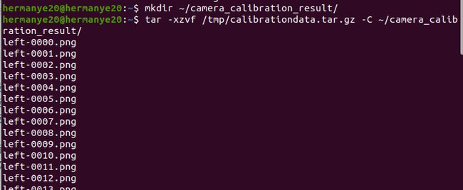
保存的结果将被自动保存在/tmp目录下,名为calibrationdata.tar.gz
('Wrote calibration data to', '/tmp/calibrationdata.tar.gz')
通过以下命令将其解压到$HOME目录
# Create dir
mkdir ~/camera_calibration_result/
# Unzip
tar -xzvf /tmp/calibrationdata.tar.gz -C ~/camera_calibration_result/
# Go home
cd ~
标定结果
查看解压到$HOME目录下的标定结果ost.txt或者ost.yaml:
# ost.txt
# oST version 5.0 parameters


[image]

width
1280

height
720

[narrow_stereo]

camera matrix
911.053619 0.000000 651.739848
0.000000 906.641596 351.747917
0.000000 0.000000 1.000000

distortion
0.102865 -0.173613 0.001142 0.005375 0.000000

rectification
1.000000 0.000000 0.000000
0.000000 1.000000 0.000000
0.000000 0.000000 1.000000

projection
918.415080 0.000000 660.158706 0.000000
0.000000 923.612822 352.392856 0.000000
0.000000 0.000000 1.000000 0.000000
# ost.yaml
image_width: 1280
image_height: 720
camera_name: narrow_stereo
camera_matrix:
  rows: 3
  cols: 3
  data: [911.05362,   0.     , 651.73985,
           0.     , 906.6416 , 351.74792,
           0.     ,   0.     ,   1.     ]
distortion_model: plumb_bob
distortion_coefficients:
  rows: 1
  cols: 5
  data: [0.102865, -0.173613, 0.001142, 0.005375, 0.000000]
rectification_matrix:
  rows: 3
  cols: 3
  data: [1., 0., 0.,
         0., 1., 0.,
         0., 0., 1.]
projection_matrix:
  rows: 3
  cols: 4
  data: [918.41508,   0.     , 660.15871,   0.     ,
           0.     , 923.61282, 352.39286,   0.     ,
           0.     ,   0.     ,   1.     ,   0.     ]
和Intel 原厂标定的结果作对比,可以发现参数差不多:
D: [0.0, 0.0, 0.0, 0.0, 0.0]
K: [911.4010620117188, 0.0, 645.8338623046875, 0.0, 910.145263671875, 347.9687194824219, 0.0, 0.0, 1.0]
R: [1.0, 0.0, 0.0, 0.0, 1.0, 0.0, 0.0, 0.0, 1.0]
P: [911.4010620117188, 0.0, 645.8338623046875, 0.0, 0.0, 910.145263671875, 347.9687194824219, 0.0, 0.0, 0.0, 1.0, 0.0]
后续
对于普通未经标定的相机,此时就可以用相机的手段进行内参数据的更新
对于Intel Realsense相机,参考MartyG所述,Realsense相机在出厂前已经标注过,因此通常不再需要再次标注内参。
因此,本文只是拿Realsense相机作为例子,这篇文章仍适用于其他需要人工标定的相机。
MartyG
3 years ago Edited
As well as the Dynamic Calibrator tool, you can also use an On-Chip Calibration tool that is built into the RealSense Viewer program to test the camera and provide a ‘heath check’ value for the calibration. There is a Tare tool in the Viewer too for improving depth measuring accuracy. Both tools can be found in a menu under the More option at the top of the Viewer’s options side-panel, and Intel have published a white-paper guide to use of On-Chip Calibration and Tare.
https://dev.intelrealsense.com/docs/self-calibration-for-depth-cameras
I would recommend using the Dynamic Calibrator when you need to perform a thorough and robust calibration of the camera’s imager components, and use On-Chip Calibration for more regular checks.
There is also the option of testing depth image quality and receiving feedback about it (such as the amount of error) using the Depth Quality Tool.
The normal version of the Dynamic Calibrator tool only calibrate extrinsics because it is extrinsics that have the most effect on depth quality. Users of the OEM version of the tool have the option of calibrating intrinsics too, though that system is aimed at engineering departments and manufacturing facilities, and 99% of RealSense users will not require it.
部分参考资料
https://wiki.ros.org/image_pipeline/CameraInfo
http://wiki.ros.org/camera_calibration
http://wiki.ros.org/camera_calibration/Tutorials/StereoCalibration


