gazebo和moveit联合机械臂运动规划仿真(包含realsense视觉点云)
1、gazebo仿真环境搭建
最终的场景:

使用的机械臂:AR3工业六轴机械臂
系统环境: ubuntu18 + ros-melodic
注:机械臂description包在github上下载的, 自己又对gazebo环境做了相应的修改。
下面是用到的主要的urdf描述文件:
<?xml version="1.0" encoding="utf-8"?>
<!-- =================================================================================== -->
<!-- |    This document was autogenerated by xacro from ar3.urdf                       | -->
<!-- |    EDITING THIS FILE BY HAND IS NOT RECOMMENDED but it was unfortunately        | -->
<!-- =================================================================================== -->
<robot name="ar3" xmlns:xacro="http://www.ros.org/wiki/xacro">

  <material name="SwivelWhite">    <color rgba="1.0 1.0 1.0 1"/></material>
  <material name="SwivelLightGray"><color rgba="0.8 0.8 0.8 1"/></material>
  <material name="SwivelMedGray">  <color rgba="0.6 0.6 0.6 1"/></material>
  <material name="SwivelDarkGray"> <color rgba="0.4 0.4 0.4 1"/></material>
  <material name="SwivelRed">      <color rgba="0.5 0.4 0.4 1"/></material>
  <material name="SwivelGreen">    <color rgba="0.4 0.5 0.4 1"/></material>
  <material name="SwivelBlue">     <color rgba="0.4 0.4 0.5 1"/></material>

  <xacro:property name = "pi" value = "3.1415927" />

  <xacro:include filename="$(find realsense_ros_gazebo)/xacro/tracker.xacro"/>
  <xacro:include filename="$(find realsense_ros_gazebo)/xacro/depthcam.xacro"/>

  <xacro:realsense_d435 sensor_name="d435" parent_link="base_link" rate="10">
    <origin rpy="${pi/2} ${pi/2} 0 " xyz="0 -0.35 0.7"/>
  </xacro:realsense_d435>


  <link name="world" />

  <link name="base_link">
    <inertial>
      <origin rpy="0 0 0" xyz="-4.6941E-06 0.054174 0.038824"/>
      <mass value="0.7102"/>
      <inertia ixx="0.0039943" ixy="3.697E-07" ixz="-5.7364E-08" iyy="0.0014946" iyz="-0.00036051" izz="0.0042554"/>
    </inertial>
    <visual>
      <origin rpy="0 0 0" xyz="0 0 0"/>
      <geometry>
        <mesh filename="package://ar3_description/meshes/base_link.STL"/>
      </geometry>
      <material name="">
        <color rgba="1 1 0 1"/>
      </material>
    </visual>
    <collision>
      <origin rpy="0 0 0" xyz="0 0 0"/>
      <geometry>
        <mesh filename="package://ar3_description/meshes/base_link.STL"/>
      </geometry>
    </collision>
  </link>

  <joint name="joint_world" type="fixed">
    <parent link="world"/>
    <child link="base_link"/>
    <origin xyz="0 0 0" rpy="0 0 0" />
  </joint>

  <link name="link_1">
    <inertial>
      <origin rpy="0 0 0" xyz="-0.022706 0.04294 -0.12205"/>
      <mass value="0.88065"/>
      <inertia ixx="0.0034" ixy="0.00042296" ixz="-0.00089231" iyy="0.0041778" iyz="0.0010848" izz="0.0027077"/>
    </inertial>
    <visual>
      <origin rpy="0 0 0" xyz="0 0 0"/>
      <geometry>
        <mesh filename="package://ar3_description/meshes/link_1.STL"/>
      </geometry>
      <material name="">
        <color rgba="1 1 0 1"/>
      </material>
    </visual>
    <collision>
      <origin rpy="0 0 0" xyz="0 0 0"/>
      <geometry>
        <mesh filename="package://ar3_description/meshes/link_1.STL"/>
      </geometry>
    </collision>
  </link>

  <joint name="joint_1" type="revolute">
    <origin rpy="${pi} 0 0" xyz="0 0 0.003445"/>
    <parent link="base_link"/>
    <child link="link_1"/>
    <axis xyz="0 0 1"/>
    <limit lower="-2.96706" upper="2.96706" effort="100" velocity="100"/>
  </joint>

  <link name="link_2">
    <inertial>
      <origin rpy="0 0 0" xyz="0.064818 -0.11189 -0.038671"/>
      <mass value="0.57738"/>
      <inertia ixx="0.0047312" ixy="0.0022624" ixz="0.00032144" iyy="0.0020836" iyz="-0.00056569" izz="0.0056129"/>
    </inertial>
    <visual>
      <origin rpy="0 0 0" xyz="0 0 0"/>
      <geometry>
        <mesh filename="package://ar3_description/meshes/link_2.STL"/>
      </geometry>
      <material name="">
        <color rgba="1 1 0 1"/>
      </material>
    </visual>
    <collision>
      <origin rpy="0 0 0" xyz="0 0 0"/>
      <geometry>
        <mesh filename="package://ar3_description/meshes/link_2.STL"/>
      </geometry>
    </collision>
  </link>

  <joint name="joint_2" type="revolute">
    <origin rpy="1.5708 0.5236 -1.5708" xyz="0 0.064146 -0.16608"/>
    <parent link="link_1"/>
    <child link="link_2"/>
    <axis xyz="0 0 -1"/>
    <limit lower="${-39.6 / 180.0 * pi}" upper="${pi / 2.0}" effort="100" velocity="100"/>
  </joint>

  <link name="link_3">
    <inertial>
      <origin rpy="0 0 0" xyz="-0.00029765 -0.023661 -0.0019125"/>
      <mass value="0.1787"/>
      <inertia ixx="0.0001685" ixy="-2.7713E-05" ixz="5.6885E-06" iyy="0.00012865" iyz="2.9256E-05" izz="0.00020744"/>
    </inertial>
    <visual>
      <origin rpy="0 0 0" xyz="0 0 0"/>
      <geometry>
        <mesh filename="package://ar3_description/meshes/link_3.STL"/>
      </geometry>
      <material name="">
        <color rgba="1 1 0 1"/>
      </material>
    </visual>
    <collision>
      <origin rpy="0 0 0" xyz="0 0 0"/>
      <geometry>
        <mesh filename="package://ar3_description/meshes/link_3.STL"/>
      </geometry>
    </collision>
  </link>

  <joint name="joint_3" type="revolute">
    <origin rpy="0 0 -1.04720367321" xyz="0.1525 -0.26414 0"/>
    <parent link="link_2"/>
    <child link="link_3"/>
    <axis xyz="0 0 -1"/>
    <limit lower="0.0174533" upper="2.5080381" effort="100" velocity="100"/>
  </joint>

  <link name="link_4">
    <inertial>
      <origin rpy="0 0 0" xyz="-0.0016798 -0.00057319 -0.074404"/>
      <mass value="0.34936"/>
      <inertia ixx="0.0030532" ixy="-1.8615E-05" ixz="-7.0047E-05" iyy="0.0031033" iyz="-2.3301E-05" izz="0.00022264"/>
    </inertial>
    <visual>
      <origin rpy="0 0 0" xyz="0 0 0"/>
      <geometry>
        <mesh filename="package://ar3_description/meshes/link_4.STL"/>
      </geometry>
      <material name="">
        <color rgba="1 1 0 1"/>
      </material>
    </visual>
    <collision>
      <origin rpy="0 0 0" xyz="0 0 0"/>
      <geometry>
        <mesh filename="package://ar3_description/meshes/link_4.STL"/>
      </geometry>
    </collision>
  </link>

  <joint name="joint_4" type="revolute">
    <origin rpy="1.5708 -1.2554 -1.5708" xyz="0 0 0.00675"/>
    <parent link="link_3"/>
    <child link="link_4"/>
    <axis xyz="0 0 -1"/>
    <limit lower="-2.8710666" upper="2.8710666" effort="100" velocity="100"/>
  </joint>

  <link name="link_5">
    <inertial>
      <origin rpy="0 0 0" xyz="0.0015066 -1.3102E-05 -0.012585"/>
      <mass value="0.11562"/>
      <inertia ixx="5.5035E-05" ixy="-1.019E-08" ixz="-2.6243E-06" iyy="8.2921E-05" iyz="1.4437E-08" izz="5.2518E-05"/>
    </inertial>
    <visual>
      <origin rpy="0 0 0" xyz="0 0 0"/>
      <geometry>
        <mesh filename="package://ar3_description/meshes/link_5.STL"/>
      </geometry>
      <material name="">
        <color rgba="1 1 0 1"/>
      </material>
    </visual>
    <collision>
      <origin rpy="0 0 0" xyz="0 0 0"/>
      <geometry>
        <mesh filename="package://ar3_description/meshes/link_5.STL"/>
      </geometry>
    </collision>
  </link>

  <joint name="joint_5" type="revolute">
    <origin rpy="${pi} 0 -2.8262" xyz="0 0 -0.22225"/>
    <parent link="link_4"/>
    <child link="link_5"/>
    <axis xyz="1 0 0"/>
    <limit lower="-1.81776042" upper="1.81776042" effort="100" velocity="100"/>
  </joint>

  <link name="link_6">
    <inertial>
      <origin rpy="0 0 0" xyz="2.9287E-10 -1.6472E-09 0.0091432"/>
      <mass value="0.013863"/>
      <inertia ixx="1.3596E-06" ixy="3.0585E-13" ixz="5.7102E-14" iyy="1.7157E-06" iyz="6.3369E-09" izz="2.4332E-06"/>
    </inertial>
    <visual>
      <origin rpy="0 0 0" xyz="0 0 0"/>
      <geometry>
        <mesh filename="package://ar3_description/meshes/link_6.STL"/>
      </geometry>
      <material name="">
        <color rgba="1 1 0 1"/>
      </material>
    </visual>
    <collision>
      <origin rpy="0 0 0" xyz="0 0 0"/>
      <geometry>
        <mesh filename="package://ar3_description/meshes/link_6.STL"/>
      </geometry>
    </collision>
  </link>

  <joint name="joint_6" type="revolute">
    <origin rpy="0 0 3.1416" xyz="-0.000294 0 0.02117"/>
    <parent link="link_5"/>
    <child link="link_6"/>
    <axis xyz="0 0 1"/>
    <limit lower="-2.5848326" upper="2.5848326" effort="100" velocity="100"/>
  </joint>

  <!-- add table -->
  <link name="table">
    <visual>
      <origin xyz="0 0 0" rpy="0 0 0" />
      <geometry >
				<box size="0.5 0.3 0.01" />
      </geometry>
        <material name="SwivelLightGray" />
    </visual>
    <collision>
      <origin xyz="0 0 0" rpy="0 0 0" />
      <geometry >
				<box size="0.7 0.5 0.01" />
      </geometry>
    </collision>
    <inertial>
      <mass value="9"/>
      <inertia ixx="9.0" ixy="0.0" ixz="0.0" iyy="9.0" iyz="0.0" izz="9.0"/>
    </inertial>
  </link>

  <joint name="world_table" type="fixed">
    <parent link="world"/>
    <child link="table"/>
    <origin xyz="0 -0.4 0.25" rpy="0 0 0" />
  </joint>

  <gazebo reference="table">
       <material>Gazebo/LightGray</material>
  </gazebo>

  <!-- add box1 -->
  <link name="box1">
    <visual>
      <origin xyz="0 0 0" rpy="0 0 0" />
      <geometry >
				<box size="0.05 0.05 0.08" />
      </geometry>
        <material name="SwivelRed" />
    </visual>
    <collision>
      <origin xyz="0 0 0" rpy="0 0 0" />
      <geometry >
				<box size="0.05 0.05 0.08" />
      </geometry>
    </collision>
    <inertial>
      <mass value="9"/>
      <inertia ixx="9.0" ixy="0.0" ixz="0.0" iyy="9.0" iyz="0.0" izz="9.0"/>
    </inertial>
  </link>

  <joint name="table_box1" type="fixed">
    <parent link="table"/>
    <child link="box1"/>
    <origin xyz="0 0 0.04" rpy="0 0 0" />
  </joint>

  <gazebo reference="box1">
       <material>Gazebo/Red</material>
  </gazebo>

  <!-- add box2 -->
  <link name="box2">
    <visual>
      <origin xyz="0 0 0" rpy="0 0 0" />
      <geometry >
				<box size="0.04 0.04 0.04" />
      </geometry>
        <material name="SwivelGreen" />
    </visual>
    <collision>
      <origin xyz="0 0 0" rpy="0 0 0" />
      <geometry >
				<box size="0.04 0.04 0.04" />
      </geometry>
    </collision>
    <inertial>
      <mass value="9"/>
      <inertia ixx="9.0" ixy="0.0" ixz="0.0" iyy="9.0" iyz="0.0" izz="9.0"/>
    </inertial>
  </link>

  <joint name="table_box2" type="fixed">
    <parent link="table"/>
    <child link="box2"/>
    <origin xyz="0.1 0.05 0.025" rpy="0 0 0" />
  </joint>

  <gazebo reference="box2">
       <material>Gazebo/Green</material>
  </gazebo>

  <!-- add cylinder1 -->
  <link name="cylinder1">
    <visual>
      <origin xyz="0 0 0" rpy="0 0 0" />
      <geometry >
				<cylinder length="0.02" radius="0.03"/>
      </geometry>
        <material name="SwivelGreen" />
    </visual>
    <collision>
      <origin xyz="0 0 0" rpy="0 0 0" />
      <geometry >
				<cylinder length="0.02" radius="0.03"/>
      </geometry>
    </collision>
    <inertial>
      <mass value="9"/>
      <inertia ixx="9.0" ixy="0.0" ixz="0.0" iyy="9.0" iyz="0.0" izz="9.0"/>
    </inertial>
  </link>

  <joint name="table_cylinder1" type="fixed">
    <parent link="table"/>
    <child link="cylinder1"/>
    <origin xyz="-0.1 0.05 0.015" rpy="0 0 0" />
  </joint>

  <gazebo reference="cylinder1">
       <material>Gazebo/Blue</material>
  </gazebo>

  <!-- add box3 -->
  <link name="box3">
    <visual>
      <origin xyz="0 0 0" rpy="0 0 0" />
      <geometry >
				<box size="0.02 0.02 0.02" />
      </geometry>
        <material name="SwivelRed" />
    </visual>
    <collision>
      <origin xyz="0 0 0" rpy="0 0 0" />
      <geometry >
				<box size="0.02 0.02 0.02" />
      </geometry>
    </collision>
    <inertial>
      <mass value="9"/>
      <inertia ixx="9.0" ixy="0.0" ixz="0.0" iyy="9.0" iyz="0.0" izz="9.0"/>
    </inertial>
  </link>

  <joint name="world_box3" type="fixed">
    <parent link="world"/>
    <child link="box3"/>
    <origin xyz="0 -0.22 0.65" rpy="0 0 0" />
  </joint>

  <gazebo reference="box3">
       <material>Gazebo/Red</material>
  </gazebo>


  <transmission name="transmission_1">
    <type>transmission_interface/SimpleTransmission</type>
    <joint name="joint_1">
        <hardwareInterface>hardware_interface/PositionJointInterface</hardwareInterface>
    </joint>
    <actuator name="motor_1">
        <hardwareInterface>hardware_interface/PositionJointInterface</hardwareInterface>
        <mechanicalReduction>1</mechanicalReduction>
    </actuator>
  </transmission>

  <transmission name="transmission_2">
      <type>transmission_interface/SimpleTransmission</type>
      <joint name="joint_2">
          <hardwareInterface>hardware_interface/PositionJointInterface</hardwareInterface>
      </joint>
      <actuator name="motor_2">
          <hardwareInterface>hardware_interface/PositionJointInterface</hardwareInterface>
          <mechanicalReduction>1</mechanicalReduction>
      </actuator>
  </transmission>

  <transmission name="transmission_3">
      <type>transmission_interface/SimpleTransmission</type>
      <joint name="joint_3">
          <hardwareInterface>hardware_interface/PositionJointInterface</hardwareInterface>
      </joint>
      <actuator name="motor_3">
          <hardwareInterface>hardware_interface/PositionJointInterface</hardwareInterface>
          <mechanicalReduction>1</mechanicalReduction>
      </actuator>
  </transmission>

  <transmission name="transmission_4">
      <type>transmission_interface/SimpleTransmission</type>
      <joint name="joint_4">
          <hardwareInterface>hardware_interface/PositionJointInterface</hardwareInterface>
      </joint>
      <actuator name="motor_4">
          <hardwareInterface>hardware_interface/PositionJointInterface</hardwareInterface>
          <mechanicalReduction>1</mechanicalReduction>
      </actuator>
  </transmission>

  <transmission name="transmission_5">
      <type>transmission_interface/SimpleTransmission</type>
      <joint name="joint_5">
          <hardwareInterface>hardware_interface/PositionJointInterface</hardwareInterface>
      </joint>
      <actuator name="motor_5">
          <hardwareInterface>hardware_interface/PositionJointInterface</hardwareInterface>
          <mechanicalReduction>1</mechanicalReduction>
      </actuator>
  </transmission>

  <transmission name="transmission_6">
      <type>transmission_interface/SimpleTransmission</type>
      <joint name="joint_6">
          <hardwareInterface>hardware_interface/PositionJointInterface</hardwareInterface>
      </joint>
      <actuator name="motor_6">
          <hardwareInterface>hardware_interface/PositionJointInterface</hardwareInterface>
          <mechanicalReduction>1</mechanicalReduction>
      </actuator>
  </transmission>

  <gazebo>
    <plugin name="gazebo_ros_control" filename="libgazebo_ros_control.so">
    <controlPeriod>0.05</controlPeriod>
    <legacyModeNS>true</legacyModeNS>
    </plugin>
  </gazebo>
  <gazebo reference="base_link">
      <selfCollide>true</selfCollide>
  </gazebo>
  <gazebo reference="link_1">
      <selfCollide>true</selfCollide>
  </gazebo>
  <gazebo reference="link_2">
      <selfCollide>true</selfCollide>
  </gazebo>
  <gazebo reference="link_3">
      <selfCollide>true</selfCollide>
  </gazebo>
  <gazebo reference="link_4">
      <selfCollide>true</selfCollide>
  </gazebo>
  <gazebo reference="link_5">
      <selfCollide>true</selfCollide>
  </gazebo>
  <gazebo reference="link_6">
      <selfCollide>true</selfCollide>
  </gazebo>

<!--camera-->
    <!-- <link name="camera_link">
        <visual>
            <origin xyz=" 0 0 0 " rpy="${pi/2} 0 ${pi/2}" />
            <geometry>
                <mesh filename="package://ar3_description/meshes/realsense_d435.stl"/>
            </geometry>
            <material name="black">
                <color rgba="0 0 0 0.95"/>
            </material>
        </visual>
    </link>

    <joint name="camera_joint" type="fixed">
        <origin xyz="0 -0.35 0.7" rpy="${pi/2} ${pi/2} 0"/>
        <parent link="base_link"/>
        <child link="camera_link"/>
    </joint> -->

<!--gazebo-->
    <!-- <gazebo reference="camera_link">
            <sensor type="depth" name="camera">
            <update_rate>30.0</update_rate>
            <camera name="head">
                <horizontal_fov>1.3962634</horizontal_fov>
                <image>
                    <width>640</width>
                    <height>480</height>
                    <format>R8G8B8</format>
                </image>
                <clip>
                    <near>0.02</near>
                    <far>300</far>
                </clip>
            </camera>

            <plugin name="kinect_camera_controller" filename="libgazebo_ros_openni_kinect.so">
                <alwaysOn>true</alwaysOn>
                <updateRate>10</updateRate>
                <cameraName>camera</cameraName>
                <imageTopicName>rgb/image_raw</imageTopicName>

                <depthImageTopicName>depth/image_raw</depthImageTopicName>
		            <pointCloudTopicName>depth/points</pointCloudTopicName>
                <cameraInfoTopicName>rgb/camera_info</cameraInfoTopicName>
	            	<depthImageCameraInfoTopicName>depth/camera_info</depthImageCameraInfoTopicName>
                <frameName>camera_depth_optical_frame</frameName>
                <baseline>0.1</baseline>
                <distortion_k1>0.0</distortion_k1>
                <distortion_k2>0.0</distortion_k2>
                <distortion_k3>0.0</distortion_k3>
                <distortion_t1>0.0</distortion_t1>
                <distortion_t2>0.0</distortion_t2>
                <pointCloudCutoff>0.4</pointCloudCutoff>
            </plugin>
        </sensor>
    </gazebo> -->

</robot>
1.1 URDF文件解释
<xacro:include filename="$(find realsense_ros_gazebo)/xacro/tracker.xacro"/>
  <xacro:include filename="$(find realsense_ros_gazebo)/xacro/depthcam.xacro"/>

  <xacro:realsense_d435 sensor_name="d435" parent_link="base_link" rate="10">
    <origin rpy="${pi/2} ${pi/2} 0 " xyz="0 -0.35 0.7"/>
  </xacro:realsense_d435>
这一部分是引用realsense相机的urdf文件,加入到机械臂描述文件中。realsense相机描述文件在github上也可以下载。
<origin rpy="${pi/2} ${pi/2} 0 " xyz="0 -0.35 0.7"/>
这条语句描述的是相机的link相对于base_link的坐标变换,即坐标是(0,-0.35,0.7),姿态是先绕着相机自身坐标系的y轴按右手定则转90度,然后绕着新的坐标系的x轴转90度。
  <!-- add table -->
  <link name="table">
    <visual>
      <origin xyz="0 0 0" rpy="0 0 0" />
      <geometry >
				<box size="0.5 0.3 0.01" />
      </geometry>
        <material name="SwivelLightGray" />
    </visual>
    <collision>
      <origin xyz="0 0 0" rpy="0 0 0" />
      <geometry >
				<box size="0.7 0.5 0.01" />
      </geometry>
    </collision>
    <inertial>
      <mass value="9"/>
      <inertia ixx="9.0" ixy="0.0" ixz="0.0" iyy="9.0" iyz="0.0" izz="9.0"/>
    </inertial>
  </link>

  <joint name="world_table" type="fixed">
    <parent link="world"/>
    <child link="table"/>
    <origin xyz="0 -0.4 0.25" rpy="0 0 0" />
  </joint>

  <gazebo reference="table">
       <material>Gazebo/LightGray</material>
  </gazebo>
这一段的作用是在环境里添加桌子,主要包含 link , joint, gazebo说明 三块,其中joint决定桌子的位置相对world的位置,我这里也可以写成base_link,因为我这里的world和base_link坐标系是完全重合的。可以调整桌子的高度和距离机械臂的距离,不能太近,太近会撞到机械臂。
box放在桌子上作为物体,还加了一个障碍物作为机械臂moveit规划的避障物体。
1.2 启动gazebo
执行 roslaunch ar3_gazebo ar3_gazebo_bringup.launch
启动gazebo仿真环境,出现下面场景:
 终端可能会报错:
 这个不影响使用,可以不用管。
2、moveit配置
moveit官方教程:
https://moveit.picknik.ai/galactic/doc/tutorials/quickstart_in_rviz/quickstart_in_rviz_tutorial.html
安装moveit,可以使用moveit的配置助手
roslaunch moveit_setup_assistant setup_assistant.launch
官方教程也有给出。配置完成后,生成机械臂的moveit包。这里主要说一下规划组的运动学解算器的设置,在kinematic.yaml文件中:
manipulator:
  # kinematics_solver: kdl_kinematics_plugin/KDLKinematicsPlugin
  kinematics_solver: trac_ik_kinematics_plugin/TRAC_IKKinematicsPlugin
  kinematics_solver_search_resolution: 0.005
  kinematics_solver_timeout: 0.005
原本的解算器是kinematics_solver: kdl_kinematics_plugin/KDLKinematicsPlugin
改成了: kinematics_solver: trac_ik_kinematics_plugin/TRAC_IKKinematicsPlugin
有人说如果出现规划失败的问题:ABORTED: No motion plan found. No execution attempted.
就可以尝试换一下这个运动学插件。
如果换完之后编译出现缺少什么trac_ik包,安装即可。
修改默认的路径搜索算法
另外一点是在ompl_planning.yaml文件中,最后是
manipulator:
  default_planner_config: RRTkConfigDefault
  planner_configs:
    - SBLkConfigDefault
    - ESTkConfigDefault
    - LBKPIECEkConfigDefault
    - BKPIECEkConfigDefault
    - KPIECEkConfigDefault
    - RRTkConfigDefault
    - RRTConnectkConfigDefault
    - RRTstarkConfigDefault
    - TRRTkConfigDefault
    - PRMkConfigDefault
    - PRMstarkConfigDefault
    - FMTkConfigDefault
    - BFMTkConfigDefault
    - PDSTkConfigDefault
    - STRIDEkConfigDefault
    - BiTRRTkConfigDefault
    - LBTRRTkConfigDefault
    - BiESTkConfigDefault
    - ProjESTkConfigDefault
    - LazyPRMkConfigDefault
    - LazyPRMstarkConfigDefault
    - SPARSkConfigDefault
    - SPARStwokConfigDefault
  projection_evaluator: joints(joint_1,joint_2)
  longest_valid_segment_fraction: 0.005
其中,default_planner_config: RRTkConfigDefault是我后来添加的,可以删去,这里是设置默认的路径搜索算法(我个人理解),可以设置成其他的,从下面列出的之中选择。
3、启动moveit仿真环境
执行 roslaunch ar3_moveit_config ar3_moveit_bringup_demo.launch
这里我改了一下原有的启动文件,应该也可以直接使用原来的启动文件,我修改之后的ar3_moveit_bringup_demo.launch如下:
<launch>
    <!-- <rosparam command="load" file="$(find ar3_moveit_config)/config/joint_names.yaml" /> -->

    <include file="$(find ar3_moveit_config)/launch/planning_context.launch">
        <arg name="load_robot_description" value="false"/>
    </include>

    <node name="joint_state_publisher" pkg="joint_state_publisher" type="joint_state_publisher">
        <!-- <param name="/use_gui" value="true"/> -->
        <rosparam param="/source_list">[/joint_states]</rosparam>
    </node>

    <!-- Run the main MoveIt executable without trajectory execution (we do not have controllers configured by default) -->
    <include file="$(find ar3_moveit_config)/launch/move_group.launch">
        <arg name="allow_trajectory_execution" value="true"/>

    </include>

    <include file="$(find ar3_moveit_config)/launch/moveit_rviz.launch">
        <arg name="config" value="true"/>
    </include>

    <!-- World to base transform -->
    <node pkg="tf" type="static_transform_publisher" name="world_broadcaster" args = "0 0 0 0 0 0 world base_link 10" />

</launch>
启动moveit,并会打开rviz
 左下角是realense的rgb图像,右侧是机械臂+相机+桌子和物体+上方障碍物。
下面说一下坐标系的转换关系,这个对之后的物体坐标变换十分重要。
首先看一下world的frame和 base_link的frame,realsense的link的frame和table的frame,总共4个坐标系。
 左上角是相机link的frame,左下角是桌面的frame,右下角有world和base_link的frame,两个坐标系完全重合了。坐标系的颜色 R G B对应x y z轴。
然后是深度点云坐标系和world坐标系的关系
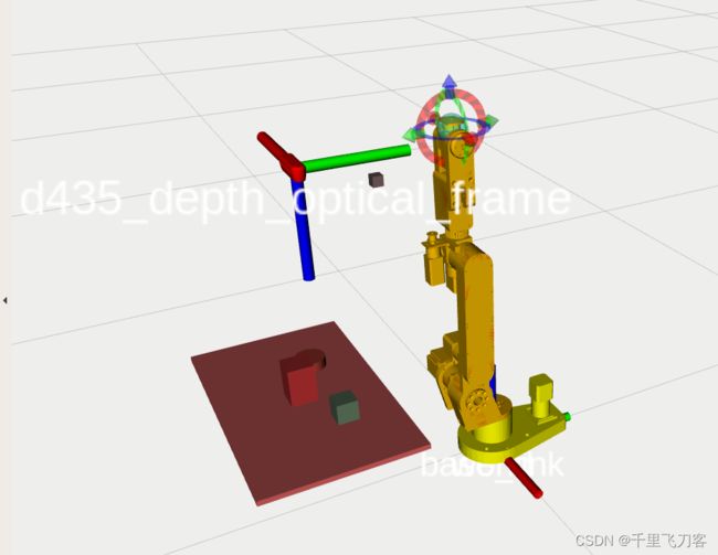 可以发现深度点云坐标系的z轴是向下的,这里注意,之后相机发布的点云坐标,都是相对于这个
d435_depth_optical_frame的,都在这个坐标系下。因此从点云坐标,转换到base_link坐标系下,需要的过程是:
点云坐标 乘以 d435_depth_optical_frame相对于base_link的变换矩阵
这一点非常重要!!
4、利用深度相机获取目标点,并使用moveit规划路径
这一步是自己编写程序,订阅深度相机发布的点云话题,并声明一个moveit规划对象,设置目标的位置和姿态之后,使用moveit规划出路径并执行,然后gazebo中的机械臂就开始动了。
还是参考了官方文档:官方教程
官方使用了rviz自带的一个小界面,需要不断点next,我做了修改,代码如下
// email:[email protected]
#include 这个代码做了如下事情:
1、订阅realsense发布的点云话题,获取点云坐标;
2、遍历所有点云,找到了桌面上处于最高位置的点;
3、找出了在最高位置的点附近的点,并求这些点的平均x坐标和y坐标,以此作为最终目标的x 和y,最终目标的z还是用的是最高位置点的z;
4、把目标的(x,y,z)坐标乘以 d435_depth_optical_frame相对于base_link的变换矩阵,得到目标在base_link下的坐标;
5、手动设置目标的姿态,姿态就让末端link_6朝下,直接通过rpy姿态角度转四元数;
6、把目标的姿态和位置复赋值给 geometry_msgs::Pose target_pose1;,这里我把z加了0。02m,如果不加,可能在后面的路径规划的时候,会报错,显示无法规划出一条可行路径,原因就是目标点与其他物体非常接近,或者就在其他物体内部,不管怎么规划,机械臂最终都会和其他物体发生碰撞,所以显示规划失败,解决方法是设置合理的目标点,避免根其他物体相碰撞;
7、使用moceit规划一条路径,并执行。
视频效果:
gazebo仿真动画
5.资源包链接
包含机械臂描述文件和moveit配置文件,以及机械臂运动仿真的一个demo
更新工作
1、在ar3机械臂上实现物块抓取仿真;gazbeo中抓取需要一个grasp插件,不然就会抓不起来,在此感谢博客gazebo仿真 UR10 + robotiq140抓取物体失败:滑出或滑落 和 Gazebo插件Grasp_fix介绍与踩坑 的分享。
2、抓取插件的git链接:
gazebo-pkgs
general-message-pkgs
这两个包的使用方法是,直接放到工作空间的 src 下,然后编译,然后在自己的机械臂描述文件 xacro 中加入插件
<gazebo>
     <plugin name="gazebo_grasp_fix" filename="libgazebo_grasp_fix.so">
           <arm>
             <arm_name>ur5_gripper</arm_name>
             <palm_link>wrist_3_link</palm_link>
             <gripper_link>gripper_finger1_finger_tip_link</gripper_link>
             <gripper_link>gripper_finger2_finger_tip_link</gripper_link>
             <gripper_link>gripper_finger2_knuckle_link</gripper_link>
             <gripper_link>gripper_finger1_knuckle_link</gripper_link>
             <gripper_link>gripper_finger1_inner_knuckle_link</gripper_link>
             <gripper_link>gripper_finger2_inner_knuckle_link</gripper_link>
           </arm>
       <forces_angle_tolerance>150</forces_angle_tolerance>
       <update_rate>130</update_rate>
       <grip_count_threshold>2</grip_count_threshold>
       <max_grip_count>8</max_grip_count>
       <release_tolerance>0.01</release_tolerance>
       <disable_collisions_on_attach>true</disable_collisions_on_attach>
       <contact_topic>__default_topic__</contact_topic>
     </plugin>
   </gazebo>
代码直接粘贴别人的,原文链接在此,主要是 libgazebo_grasp_fix.so 这个链接库。我使用的时候这个 palm_link 不能随意设置,设置的是手指的
3、视频
ar3机械臂抓取仿真
4、控制器使用的是 position_controller , 直接控制每个关节,由于moveit没有配置成功,所以写了一个键盘控制机械臂关节转动py代码,直接手搓位置的,后面有空再修改一下,加一个逆解包进去,感觉moveit配置稍有问题就跑不起来,最好还是自己写一个。