<2021SC@SDUSC>开源游戏引擎Overload代码分析五:OvEditor——RawShaders.cpp
2021SC@SDUSC
Overload代码分析五:OvEditor——RawShaders.cpp
- 前言
- RawShaders.cpp
-
- 1.GetGrid()
-
- vertex shader
- fragment shader
- 2.GetGizmo()
-
- vertex shader
- fragment shader
- 3.GetBillboard()
-
- vertex shader
- fragment shader
- 总结
前言
这是Overload引擎相关的第七篇文章,同时也是OvEditor分析的第二篇。Overload引擎的Github主页在这里。
本篇文章主要会介绍RawShaders.cpp中的三个shader,会介绍各种shader相关的知识,比较复杂,需要花一篇文章来好好讲述。
RawShaders.cpp
1.GetGrid()
std::pair<std::string, std::string> OvEditor::Resources::RawShaders::GetGrid()
{
	std::pair<std::string, std::string> source;

	source.first = R"(
#version 430 core

layout (location = 0) in vec3 geo_Pos;
layout (location = 1) in vec2 geo_TexCoords;
layout (location = 2) in vec3 geo_Normal;

layout (std140) uniform EngineUBO
{
    mat4    ubo_Model;
    mat4    ubo_View;
    mat4    ubo_Projection;
    vec3    ubo_ViewPos;
    float   ubo_Time;
};

out VS_OUT
{
    vec3 FragPos;
    vec2 TexCoords;
} vs_out;

void main()
{
    vs_out.FragPos      = vec3(ubo_Model * vec4(geo_Pos, 1.0));
    vs_out.TexCoords    = vs_out.FragPos.xz;

    gl_Position = ubo_Projection * ubo_View * vec4(vs_out.FragPos, 1.0);
}
)";

	source.second = R"(
#version 430 core

out vec4 FRAGMENT_COLOR;

layout (std140) uniform EngineUBO
{
    mat4    ubo_Model;
    mat4    ubo_View;
    mat4    ubo_Projection;
    vec3    ubo_ViewPos;
    float   ubo_Time;
};

in VS_OUT
{
    vec3 FragPos;
    vec2 TexCoords;
} fs_in;

uniform vec3 u_Color;

float MAG(float p_lp)
{
  const float lineWidth = 1.0f;

  const vec2 coord       = fs_in.TexCoords / p_lp;
  const vec2 grid        = abs(fract(coord - 0.5) - 0.5) / fwidth(coord);
  const float line       = min(grid.x, grid.y);
  const float lineResult = lineWidth - min(line, lineWidth);

  return lineResult;
}

float Grid(float height, float a, float b, float c)
{
  const float cl   = MAG(a);
  const float ml   = MAG(b);
  const float fl   = MAG(c);

  const float cmit =  10.0f;
  const float cmet =  40.0f;
  const float mfit =  80.0f;
  const float mfet =  160.0f;

  const float df   = clamp((height - cmit) / (cmet - cmit), 0.0f, 1.0f);
  const float dff  = clamp((height - mfit) / (mfet - mfit), 0.0f, 1.0f);

  const float inl  = mix(cl, ml, df);
  const float fnl  = mix(inl, fl, dff);

  return fnl;
}

void main()
{
  const float height = distance(ubo_ViewPos.y, fs_in.FragPos.y);

  const float gridA = Grid(height, 1.0f, 4.0f, 8.0f);
  const float gridB = Grid(height, 4.0f, 16.0f, 32.0f);

  const float grid  = gridA * 0.5f + gridB;

  const vec2  viewdirW    = ubo_ViewPos.xz - fs_in.FragPos.xz;
  const float viewdist    = length(viewdirW);

  FRAGMENT_COLOR = vec4(u_Color, grid);
}
)";

	return source;
}
首先我们需要声明的是,OpenGL的光栅化shader,或者说近乎所有shader语言的光栅化shader,都要分为两个部分。第一个部分对顶点,或者说几何信息做处理,而第二个部分需要对片元,或者说像素信息做处理。也就是说,第一个部分用于控制形状位置等,而第二个部分用于确定颜色。在OpenGL中,第一个部分被称作vertex shader,第二个部分则被称作fragment shader。
我们仅看由文本定义的shader,下面会逐句分析,先看source.first,也就是vertex shader所对应的:
vertex shader
#version 430 core
此行用于设定所用的glsl版本,430对应4.3版本。
layout (location = 0) in vec3 geo_Pos;
layout (location = 1) in vec2 geo_TexCoords;
layout (location = 2) in vec3 geo_Normal;

layout (std140) uniform EngineUBO
{
    mat4    ubo_Model;
    mat4    ubo_View;
    mat4    ubo_Projection;
    vec3    ubo_ViewPos;
    float   ubo_Time;
};

out VS_OUT
{
    vec3 FragPos;
    vec2 TexCoords;
} vs_out;
此处在定义所需的数据结构,location是对应的偏移,或者更易懂一点,是各变量所占的空间,也即布局(layout)方式。此处在变量类型前面的in,指的是这些属性是需要传入shader的。而下方所定义的结构体,布局方式定义为遵循std140,实际上就是一种单调递增的布局方式,结构体内部定义了多个变量属性。对std140规则感兴趣的,可以看这篇文章。在下面又是一个结构体的定义,但此结构体是vertex shader所必须的,用于传递结果到fragment shader,out就是用于表明这是需要传出的。我们可以看到,它在定义结构体的同时就创建了一个对象。
void main()
{
    vs_out.FragPos      = vec3(ubo_Model * vec4(geo_Pos, 1.0));
    vs_out.TexCoords    = vs_out.FragPos.xz;

    gl_Position = ubo_Projection * ubo_View * vec4(vs_out.FragPos, 1.0);
}
此处是这个vertex shader的主函数,也就是真正实现功能的地方。在第一行代码中,geo_Pos是当前模型在自己的模型空间内的位置,也就是模型相对于自己的位置,我们给他用1.0增加一维,以方便我们在需要时进行投影,不过在第一行代码中并没有投影。因为我们用的ubo_Model这样一个四维矩阵与位置相乘,所以必须让三维的位置信息增加一维。ubo_Model这个矩阵,是用来将一个模型空间,或者说local坐标系的位置,转到世界空间,或者说全局坐标系的。于是,我们把当前vertex shader实施的顶点对象由本地转到了全局,并把全局坐标存入了vs_out.FragPos。如果想要搞清楚我们现在和之后要提到的各种空间,可以看看这篇文章。
接下来,在第二行代码中,我们给vs_out.TexCoords赋值。TexCoords实际上就是模型表面上的坐标,或者说是贴图所需要的坐标,用于告知贴图应当怎样去贴,通常我们更喜欢叫他的小名——uv。然而此处,它直接把我们得到的世界坐标的x坐标和z坐标赋给了uv,这看起来很令人费解,但其实并不是这样。要知道,这个shader想要实现的效果是GetGrid,什么意思?是要获取网格,网格是什么呢?一般也就是一个划分过的平面,也就是说,我们是在给一个平面赋uv。一个平面一般是和xz平面平行的,甚至重合,所以对于这个平面,我们就可以直接把它的xz坐标当作是uv。
最后是第三行代码,给我们的世界坐标乘上了一个ubo_View和ubo_Projection。view矩阵是用于把世界空间的坐标转到观察空间,或者说摄像机所在的空间比较容易懂。而projection矩阵用于做投影,也就是把在观察空间的物体给投影到平面上,哪个平面呢?摄像机的镜头,通过这一步操作,我们才可以最终看到场景的物体,而且是支持透视的。支持透视是如何实现的?我们可以发现,三维的世界坐标在乘矩阵之前就被拓展到了四维,之后才开始进行各种变换,实际上,这里藏了一个隐藏步骤。在投影时,坐标的第四维,也就是w值,会被整个坐标向量同除,之后w值回到1,这是投影的步骤。通过这一步,距离镜头不同远近的物体才出现了区别。这在我上面提到的文章中,也是有提及的。
综上,我们就得到了模型真实的,可以被看到的位置,其中,gl_Position是由OpenGL直接管理的,所以它会被传到fragment shader中。
fragment shader
接下来就是source.second所定义的,也就是fragment shader:
out vec4 FRAGMENT_COLOR;

layout (std140) uniform EngineUBO
{
    mat4    ubo_Model;
    mat4    ubo_View;
    mat4    ubo_Projection;
    vec3    ubo_ViewPos;
    float   ubo_Time;
};

in VS_OUT
{
    vec3 FragPos;
    vec2 TexCoords;
} fs_in;

uniform vec3 u_Color;
这些代码就是定义变量罢了,和上面讲vertex shader时完全是一个原理,不再复述了。但有一点值得一提,此处的VS_OUT是用于接收vertex shader中的vs_out,它在被定义时就已经接收了值,因为它是被OpenGL管理的。同时,uniform是指一个全局的变量,也就是说可以在shader中任何地方,甚至shader外也可以赋值。
float MAG(float p_lp)
{
  const float lineWidth = 1.0f;

  const vec2 coord       = fs_in.TexCoords / p_lp;
  const vec2 grid        = abs(fract(coord - 0.5) - 0.5) / fwidth(coord);
  const float line       = min(grid.x, grid.y);
  const float lineResult = lineWidth - min(line, lineWidth);

  return lineResult;
}

float Grid(float height, float a, float b, float c)
{
  const float cl   = MAG(a);
  const float ml   = MAG(b);
  const float fl   = MAG(c);

  const float cmit =  10.0f;
  const float cmet =  40.0f;
  const float mfit =  80.0f;
  const float mfet =  160.0f;

  const float df   = clamp((height - cmit) / (cmet - cmit), 0.0f, 1.0f);
  const float dff  = clamp((height - mfit) / (mfet - mfit), 0.0f, 1.0f);

  const float inl  = mix(cl, ml, df);
  const float fnl  = mix(inl, fl, dff);

  return fnl;
}

void main()
{
  const float height = distance(ubo_ViewPos.y, fs_in.FragPos.y);

  const float gridA = Grid(height, 1.0f, 4.0f, 8.0f);
  const float gridB = Grid(height, 4.0f, 16.0f, 32.0f);

  const float grid  = gridA * 0.5f + gridB;

  const vec2  viewdirW    = ubo_ViewPos.xz - fs_in.FragPos.xz;
  const float viewdist    = length(viewdirW);

  FRAGMENT_COLOR = vec4(u_Color, grid);
}
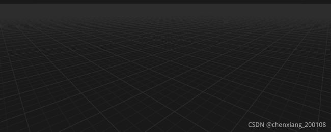
此处定义了多个函数,但我们可以看到,最后一行输出的颜色中,rgb值是由u_color,一个全局值来决定的。也就是说,最终颜色和前面的函数计算毫无关系,只有alpha值,也就是透明度,是由计算决定的。实际上,就是让网格线处的的alpha值更小,使得平面网格更加立体。
m_gridMaterial.Set("u_Color", p_color);
从EditorRenderer.cpp中的这一行,可以确定颜色是直接确定下来的。
2.GetGizmo()
std::pair<std::string, std::string> OvEditor::Resources::RawShaders::GetGizmo()
{
	std::pair<std::string, std::string> source;

	source.first = R"(
#version 430 core

layout (location = 0) in vec3 geo_Pos;
layout (location = 2) in vec3 geo_Normal;
layout (location = 1) in vec2 geo_TexCoords;

layout (std140) uniform EngineUBO
{
    mat4    ubo_Model;
    mat4    ubo_View;
    mat4    ubo_Projection;
    vec3    ubo_ViewPos;
    float   ubo_Time;
};

out VS_OUT
{
    vec3 Color;
} vs_out;

uniform bool u_IsBall;
uniform bool u_IsPickable;
uniform int u_HighlightedAxis;

mat4 rotationMatrix(vec3 axis, float angle)
{
    axis = normalize(axis);
    float s = sin(angle);
    float c = cos(angle);
    float oc = 1.0 - c;

    return mat4
    (
        oc * axis.x * axis.x + c,           oc * axis.x * axis.y - axis.z * s,  oc * axis.z * axis.x + axis.y * s,  0.0,
        oc * axis.x * axis.y + axis.z * s,  oc * axis.y * axis.y + c,           oc * axis.y * axis.z - axis.x * s,  0.0,
        oc * axis.z * axis.x - axis.y * s,  oc * axis.y * axis.z + axis.x * s,  oc * axis.z * axis.z + c,           0.0,
        0.0,                                0.0,                                0.0,                                1.0
    );
}

void main()
{
    mat4 instanceModel = ubo_Model;

    if (gl_InstanceID == 1)
        instanceModel *= rotationMatrix(vec3(0, 1, 0), radians(-90)); /* X axis */
    else if (gl_InstanceID == 2)
        instanceModel *= rotationMatrix(vec3(1, 0, 0), radians(90)); /* Y axis */

    float distanceToCamera = distance(ubo_ViewPos, instanceModel[3].xyz);

	vec3 pos = geo_Pos;

    vec3 fragPos = vec3(instanceModel * vec4(pos * distanceToCamera * 0.1f, 1.0));

	if (u_IsPickable)
	{
		int blueComponent = 0;

		if (gl_InstanceID == 1)
			blueComponent = 252;

		if (gl_InstanceID == 2)
			blueComponent = 253;

		if (gl_InstanceID == 0)
			blueComponent = 254;

		vs_out.Color = vec3(1.0f, 1.0f, blueComponent / 255.0f);
	}
	else
	{
		if (u_IsBall)
		{
			vs_out.Color = vec3(1.0f);
		}
		else
		{
			float red	= float(gl_InstanceID == 1); // X
			float green = float(gl_InstanceID == 2); // Y
			float blue	= float(gl_InstanceID == 0); // Z

			if (!u_IsPickable && ((gl_InstanceID == 1 && u_HighlightedAxis == 0) || (gl_InstanceID == 2 && u_HighlightedAxis == 1) || (gl_InstanceID == 0 && u_HighlightedAxis == 2)))
			{
				vs_out.Color = vec3(1.0f, 1.0f, 0.0f);
			}
			else
			{
				vs_out.Color = vec3(red, green, blue);
			}
		}
	}

    gl_Position = ubo_Projection * ubo_View * vec4(fragPos, 1.0);
}
)";

	source.second = R"(
#version 430 core

out vec4 FRAGMENT_COLOR;

in VS_OUT
{
    vec3 Color;
} fs_in;

uniform bool u_IsPickable;

void main()
{
	FRAGMENT_COLOR = vec4(fs_in.Color, 1.0f);
})";

	return source;
}
vertex shader
还是从vertex shader开始。
#version 430 core

layout (location = 0) in vec3 geo_Pos;
layout (location = 2) in vec3 geo_Normal;
layout (location = 1) in vec2 geo_TexCoords;

layout (std140) uniform EngineUBO
{
    mat4    ubo_Model;
    mat4    ubo_View;
    mat4    ubo_Projection;
    vec3    ubo_ViewPos;
    float   ubo_Time;
};

out VS_OUT
{
    vec3 Color;
} vs_out;

uniform bool u_IsBall;
uniform bool u_IsPickable;
uniform int u_HighlightedAxis;
这些代码都在定义变量,没有新的东西,就不再讲一遍了。
mat4 rotationMatrix(vec3 axis, float angle)
{
    axis = normalize(axis);
    float s = sin(angle);
    float c = cos(angle);
    float oc = 1.0 - c;

    return mat4
    (
        oc * axis.x * axis.x + c,           oc * axis.x * axis.y - axis.z * s,  oc * axis.z * axis.x + axis.y * s,  0.0,
        oc * axis.x * axis.y + axis.z * s,  oc * axis.y * axis.y + c,           oc * axis.y * axis.z - axis.x * s,  0.0,
        oc * axis.z * axis.x - axis.y * s,  oc * axis.y * axis.z + axis.x * s,  oc * axis.z * axis.z + c,           0.0,
        0.0,                                0.0,                                0.0,                                1.0
    );
}
定义了旋转矩阵,给定旋转轴和角度,可以获得旋转矩阵。跟数学的关系比较大,在代码实现方面并不困难,不细讲了。
void main()
{
    mat4 instanceModel = ubo_Model;

    if (gl_InstanceID == 1)
        instanceModel *= rotationMatrix(vec3(0, 1, 0), radians(-90)); /* X axis */
    else if (gl_InstanceID == 2)
        instanceModel *= rotationMatrix(vec3(1, 0, 0), radians(90)); /* Y axis */

    float distanceToCamera = distance(ubo_ViewPos, instanceModel[3].xyz);

	vec3 pos = geo_Pos;

    vec3 fragPos = vec3(instanceModel * vec4(pos * distanceToCamera * 0.1f, 1.0));

	if (u_IsPickable)
	{
		int blueComponent = 0;

		if (gl_InstanceID == 1)
			blueComponent = 252;

		if (gl_InstanceID == 2)
			blueComponent = 253;

		if (gl_InstanceID == 0)
			blueComponent = 254;

		vs_out.Color = vec3(1.0f, 1.0f, blueComponent / 255.0f);
	}
	else
	{
		if (u_IsBall)
		{
			vs_out.Color = vec3(1.0f);
		}
		else
		{
			float red	= float(gl_InstanceID == 1); // X
			float green = float(gl_InstanceID == 2); // Y
			float blue	= float(gl_InstanceID == 0); // Z

			if (!u_IsPickable && ((gl_InstanceID == 1 && u_HighlightedAxis == 0) || (gl_InstanceID == 2 && u_HighlightedAxis == 1) || (gl_InstanceID == 0 && u_HighlightedAxis == 2)))
			{
				vs_out.Color = vec3(1.0f, 1.0f, 0.0f);
			}
			else
			{
				vs_out.Color = vec3(red, green, blue);
			}
		}
	}

    gl_Position = ubo_Projection * ubo_View * vec4(fragPos, 1.0);
}
instanceModel是ubo_Model对各个轴向可视化的实例。这里以z轴为基础,当可视化x轴时,以y轴为旋转轴旋转-90度,这里可能会有一些困惑,-90度不是会与x正方向背道而驰吗?事实上,虽然主观感受上是如此,但是对于坐标轴来说,实际旋转的度数和矩阵的对应度数是相反的,也就是说这样x方向并没有问题。主要的原因基于坐标系的转换原理,在这里就不多谈了,感兴趣可以自行搜索,只要记住对坐标轴的旋转变换和对物体的旋转变换是相反的就可以了。
接着用distanceToCamera得到了观察摄像机和物体之间的距离,目的是在计算fragPos时改变观察距离对大小的影响。这样就可以让显示的坐标轴在摄像机远离时变大,而在靠近时减小,以便于观察。
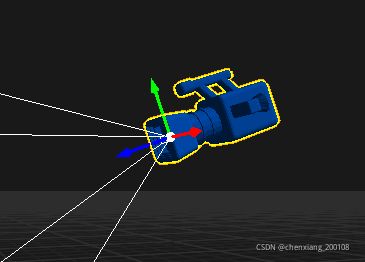
如果u_IsPickable为真,会把三个轴都显示成白色。否则进行判断,如果是轴的坐标原点(u_IsBall),则显示为白色;如果不是原点而是轴,x、y、z轴分别为红、绿、蓝,以当前渲染对象为准。如果此时对应的高亮对象(鼠标指向的轴)是当前渲染轴向,则此轴显示为黄色,否则显示为轴向对应色。
fragment shader
#version 430 core

out vec4 FRAGMENT_COLOR;

in VS_OUT
{
    vec3 Color;
} fs_in;

uniform bool u_IsPickable;

void main()
{
	FRAGMENT_COLOR = vec4(fs_in.Color, 1.0f);
}
这里没什么新的东西,简短易懂,只是把上面设定的颜色给了像素。
3.GetBillboard()
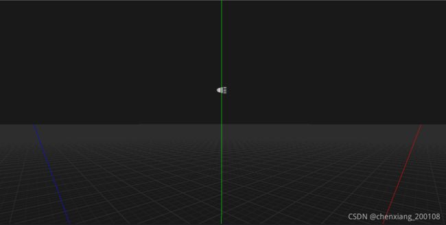
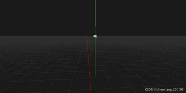
这个shader用于实现公告牌技术,就是让贴图能够随着观察的视线改变方向,减少穿帮的可能。在Overload中只用于光源的图标显示。
std::pair<std::string, std::string> OvEditor::Resources::RawShaders::GetBillboard()
{
	std::pair<std::string, std::string> source;

	source.first = R"(
#version 430 core

layout (location = 0) in vec3 geo_Pos;
layout (location = 1) in vec2 geo_TexCoords;
layout (location = 2) in vec3 geo_Normal;

layout (std140) uniform EngineUBO
{
    mat4    ubo_Model;
    mat4    ubo_View;
    mat4    ubo_Projection;
    vec3    ubo_ViewPos;
    float   ubo_Time;
};

out VS_OUT
{
    vec2 TexCoords;
} vs_out;

uniform float u_Scale = 1.0f;

void main()
{
    vs_out.TexCoords = geo_TexCoords;

    mat4 model = ubo_Model;
	float distanceToCamera = distance(ubo_ViewPos, model[3].xyz);

    mat4 modelView = ubo_View * model;

    // Column 0:
    modelView[0][0] = 1;
    modelView[0][1] = 0;
    modelView[0][2] = 0;

    // Column 1:
    modelView[1][0] = 0;
    modelView[1][1] = 1;
    modelView[1][2] = 0;

    // Column 2:
    modelView[2][0] = 0;
    modelView[2][1] = 0;
    modelView[2][2] = 1;

    gl_Position = ubo_Projection * modelView * vec4(geo_Pos * distanceToCamera * u_Scale, 1.0);
})";

	source.second = R"(
#version 430 core

out vec4 FRAGMENT_COLOR;

in VS_OUT
{
    vec2 TexCoords;
} fs_in;

uniform vec4        u_Diffuse = vec4(1.0, 1.0, 1.0, 1.0);
uniform sampler2D   u_DiffuseMap;
uniform vec2        u_TextureTiling = vec2(1.0, 1.0);
uniform vec2        u_TextureOffset = vec2(0.0, 0.0);

void main()
{
    FRAGMENT_COLOR = texture(u_DiffuseMap, u_TextureOffset + vec2(mod(fs_in.TexCoords.x * u_TextureTiling.x, 1), mod(fs_in.TexCoords.y * u_TextureTiling.y, 1))) * u_Diffuse;
})";

	return source;
}
vertex shader
#version 430 core

layout (location = 0) in vec3 geo_Pos;
layout (location = 1) in vec2 geo_TexCoords;
layout (location = 2) in vec3 geo_Normal;

layout (std140) uniform EngineUBO
{
    mat4    ubo_Model;
    mat4    ubo_View;
    mat4    ubo_Projection;
    vec3    ubo_ViewPos;
    float   ubo_Time;
};

out VS_OUT
{
    vec2 TexCoords;
} vs_out;

uniform float u_Scale = 1.0f;

void main()
{
    vs_out.TexCoords = geo_TexCoords;

    mat4 model = ubo_Model;
	float distanceToCamera = distance(ubo_ViewPos, model[3].xyz);

    mat4 modelView = ubo_View * model;

    // Column 0:
    modelView[0][0] = 1;
    modelView[0][1] = 0;
    modelView[0][2] = 0;

    // Column 1:
    modelView[1][0] = 0;
    modelView[1][1] = 1;
    modelView[1][2] = 0;

    // Column 2:
    modelView[2][0] = 0;
    modelView[2][1] = 0;
    modelView[2][2] = 1;

    gl_Position = ubo_Projection * modelView * vec4(geo_Pos * distanceToCamera * u_Scale, 1.0);
}
distanceToCamera的用处和上一个shader相同,不再复述了。
modelView矩阵把modelView的前三维更改为单位矩阵,事实上相当于让modelView矩阵只能支持平移变换,那么如果贴图所在平面一创建就对应摄像机的直视方向,自然就不会有旋转偏移,也就达成了公告牌所想要的效果。
fragment shader
#version 430 core

out vec4 FRAGMENT_COLOR;

in VS_OUT
{
    vec2 TexCoords;
} fs_in;

uniform vec4        u_Diffuse = vec4(1.0, 1.0, 1.0, 1.0);
uniform sampler2D   u_DiffuseMap;
uniform vec2        u_TextureTiling = vec2(1.0, 1.0);
uniform vec2        u_TextureOffset = vec2(0.0, 0.0);

void main()
{
    FRAGMENT_COLOR = texture(u_DiffuseMap, u_TextureOffset + vec2(mod(fs_in.TexCoords.x * u_TextureTiling.x, 1), mod(fs_in.TexCoords.y * u_TextureTiling.y, 1))) * u_Diffuse;
}
texture是采样函数,对u_DiffuseMap这张图用后一个参数(一般视作uv)进行采样,得到的值作为颜色返回。
总结
本篇文章讲了三个shader的实现,也顺带讲了一些glsl的知识,还是比较丰富的。如果有一定图形学基础,看懂这个并不困难,还是要好好努力啊。


