MDK外部Flash烧录算法文件制作
MDK外部Flash烧录算法文件制作
- 硬件平台
- 算法制作工程配置
- Flash算法驱动
-
- 修改硬件初始化代码
- 修改外部Flash的描述信息
- 完善Flash的驱动接口
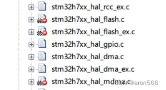
- 屏蔽无效代码
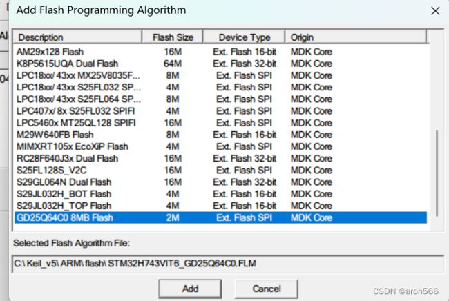
- 使用Flash算法
- 测试验证
-
- 分散加载文件的修改
- 执行编译
- 常见错误
-
- Insufficient RAM for Flash Algorithm !
- Cannot Write to RAM for Flash Algorithms !
- 下载的时候软件闪退
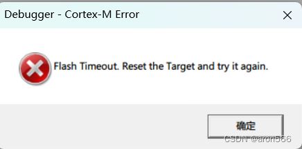
- Flash Timeout. Reset the Target and try it again.
- SPI对Flash的操作驱动异常,比如对Flash写数据,再读数据验证是否一致出现错误
- 在RAM中跑仿真正常,但是实际使用出现Timeout 超时类似于启动失败情况,无法使用Flash算法去烧录下载
- 调试方法
最近在开发LVGL时图片文件占用大量的片上存储空间,有两个外部的SPI Flash没有完全利用起来,所以研究下直接在烧录阶段将这个图片烧录进外部Flash
硬件平台
- STM32F743VIT6
- Flash:GD25Q64C(8MB的Flash)
- IDE:MDK v5.37.0.0
算法制作工程配置
可以先用CubeMX配置(外设驱动Flash)生成一个MDK工程,之后在此基础上修改!
# 拷贝Flash_Algx目录下的*.axf文件到,当前目录下改名为.FLM文件
cmd.exe /C copy "Flash_Algx\%L" ".\@L.FLM"
这里需要看看自己的axf文件生成在哪个目录下,命令改成对应的
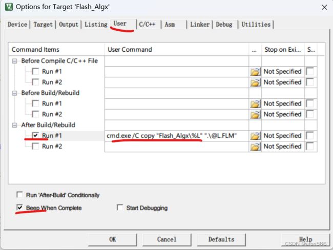
# 拷贝当前目录下名为xx.FLM文件到C:\Keil_v5\ARM\Flash\目录下
cmd.exe /C copy ".\@L.FLM" "C:\Keil_v5\ARM\Flash\@L.FLM"
调试信息一定要打开,否则即使生成了.FLM文件也识别不到

设置,代码段地址、数据段地址为相对地址,即位置无关
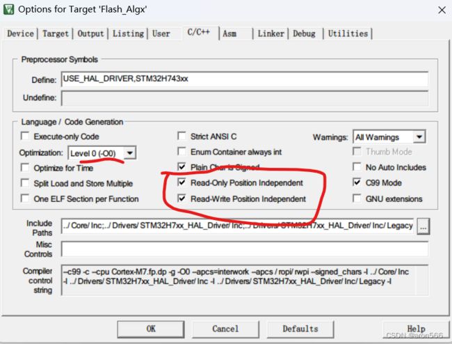

添加如下选项
# 屏蔽L6503类型警告信息
--diag_suppress L6305
; Linker Control File (scatter-loading)
;

PRG 0 PI               ; Programming Functions
{
  PrgCode +0           ; Code
  {
    * (+RO)
  }
  PrgData +0           ; Data
  {
    * (+RW,+ZI)
  }
}

DSCR +0                ; Device Description
{
  DevDscr +0
  {
    FlashDev.o
  }
}
Flash算法驱动
修改硬件初始化代码
延时接口、硬件初始化接口
HAL_StatusTypeDef HAL_InitTick(uint32_t TickPriority)
{
  return HAL_OK;
}

uint32_t HAL_GetTick(void)
{
  static uint32_t ticks = 0U;
  uint32_t i;
  for(i = (SystemCoreClock >> 14U); i > 0U; i--)
  {
    __NOP(); __NOP(); __NOP(); __NOP(); __NOP(); __NOP();
    __NOP(); __NOP(); __NOP(); __NOP(); __NOP(); __NOP();
  }
  ticks += 1;
  return ticks;
}

void HAL_Delay(uint32_t Delay)
{
  uint32_t tickstart = HAL_GetTick();
  uint32_t wait = Delay;
  if(wait < HAL_MAX_DELAY)
  {
    wait += (uint32_t)(HAL_TICK_FREQ_DEFAULT);
  }
  while((HAL_GetTick() - tickstart) < wait)
  {
    __NOP();
  }
}

/* USER CODE END 0 */

/**
  * @brief  The application entry point.
  * @retval int
  */
int Xmain(void)
{
  /* USER CODE BEGIN 1 */
  SystemInit();
  /* USER CODE END 1 */

  /* MPU Configuration--------------------------------------------------------*/

  /* Enable I-Cache---------------------------------------------------------*/

  /* Enable D-Cache---------------------------------------------------------*/

  /* MCU Configuration--------------------------------------------------------*/

  /* Reset of all peripherals, Initializes the Flash interface and the Systick. */

  /* USER CODE BEGIN Init */

  /* USER CODE END Init */

  /* Configure the system clock */
  SystemClock_Config();

  /* USER CODE BEGIN SysInit */

  /* USER CODE END SysInit */

  /* Initialize all configured peripherals */
  MX_GPIO_Init();
  MX_USART2_UART_Init();
  MX_SPI6_Init();
  /* USER CODE BEGIN 2 */

  /* USER CODE END 2 */

  /* Infinite loop */
  /* USER CODE BEGIN WHILE */
  return 0;
  //while (1);
  /* USER CODE END WHILE */

  /* USER CODE BEGIN 3 */

  /* USER CODE END 3 */
}

/**
  * @brief System Clock Configuration
  * @retval None
  */
void SystemClock_Config(void)
{
  RCC_OscInitTypeDef RCC_OscInitStruct = {0};
  RCC_ClkInitTypeDef RCC_ClkInitStruct = {0};

  /** Supply configuration update enable
  */
  HAL_PWREx_ConfigSupply(PWR_LDO_SUPPLY);

  /** Configure the main internal regulator output voltage
  */
  __HAL_PWR_VOLTAGESCALING_CONFIG(PWR_REGULATOR_VOLTAGE_SCALE1);

  while(!__HAL_PWR_GET_FLAG(PWR_FLAG_VOSRDY)) {}

  /** Macro to configure the PLL clock source
  */
  __HAL_RCC_PLL_PLLSOURCE_CONFIG(RCC_PLLSOURCE_HSE);

  /** Initializes the RCC Oscillators according to the specified parameters
  * in the RCC_OscInitTypeDef structure.
  */
  RCC_OscInitStruct.OscillatorType = RCC_OSCILLATORTYPE_HSE;
  RCC_OscInitStruct.HSEState = RCC_HSE_ON;
  RCC_OscInitStruct.PLL.PLLState = RCC_PLL_ON;
  RCC_OscInitStruct.PLL.PLLSource = RCC_PLLSOURCE_HSE;
  RCC_OscInitStruct.PLL.PLLM = 2;
  RCC_OscInitStruct.PLL.PLLN = 64;
  RCC_OscInitStruct.PLL.PLLP = 2;
  RCC_OscInitStruct.PLL.PLLQ = 10;
  RCC_OscInitStruct.PLL.PLLR = 2;
  RCC_OscInitStruct.PLL.PLLRGE = RCC_PLL1VCIRANGE_3;
  RCC_OscInitStruct.PLL.PLLVCOSEL = RCC_PLL1VCOWIDE;
  RCC_OscInitStruct.PLL.PLLFRACN = 0;
  if (HAL_RCC_OscConfig(&RCC_OscInitStruct) != HAL_OK)
  {
    Error_Handler();
  }

  /** Initializes the CPU, AHB and APB buses clocks
  */
  RCC_ClkInitStruct.ClockType = RCC_CLOCKTYPE_HCLK|RCC_CLOCKTYPE_SYSCLK
                              |RCC_CLOCKTYPE_PCLK1|RCC_CLOCKTYPE_PCLK2
                              |RCC_CLOCKTYPE_D3PCLK1|RCC_CLOCKTYPE_D1PCLK1;
  RCC_ClkInitStruct.SYSCLKSource = RCC_SYSCLKSOURCE_PLLCLK;
  RCC_ClkInitStruct.SYSCLKDivider = RCC_SYSCLK_DIV1;
  RCC_ClkInitStruct.AHBCLKDivider = RCC_HCLK_DIV2;
  RCC_ClkInitStruct.APB3CLKDivider = RCC_APB3_DIV2;
  RCC_ClkInitStruct.APB1CLKDivider = RCC_APB1_DIV4;
  RCC_ClkInitStruct.APB2CLKDivider = RCC_APB2_DIV2;
  RCC_ClkInitStruct.APB4CLKDivider = RCC_APB4_DIV2;

  if (HAL_RCC_ClockConfig(&RCC_ClkInitStruct, FLASH_LATENCY_2) != HAL_OK)
  {
    Error_Handler();
  }
}
修改外部Flash的描述信息
这里定义了,2MB的 Flash,Flash实际总大小8MB,我只用其中的2MB去用于烧录阶段,所以这里定义了0x00200000大小,Device Start Address字段定义了这段空间在程序中的位置(配合sct文件,注意不要与片内的地址重合),其他就是页大小,扇区大小,按实际填写即可
struct FlashDevice const FlashDevice  =  {
   FLASH_DRV_VERS,             // Driver Version, do not modify!
   "GD25Q64C0 8MB Flash",      // Device Name
   EXTSPI,                     // Device Type
   0x90000000,                 // Device Start Address
   0x00200000,                 // Device Size in Bytes (2MB)
   256,                       // Programming Page Size
   0,                          // Reserved, must be 0
   0xFF,                       // Initial Content of Erased Memory
   3000,                        // Program Page Timeout 100 mSec
   6000,                       // Erase Sector Timeout 3000 mSec

// Specify Size and Address of Sectors
   0x001000, 0,               // Sector Size  4kB (512 Sectors)
   SECTOR_END
};
完善Flash的驱动接口
完善FlashPrg.c文件中的驱动接口,在初始化中加入硬件的初始化代码Xmian()例如这样
/**************************************************************************//**
 * @file     FlashPrg.c
 * @brief    Flash Programming Functions adapted for New Device Flash
 * @version  V1.0.0
 * @date     10. January 2018
 ******************************************************************************/
/*
 * Copyright (c) 2010-2018 Arm Limited. All rights reserved.
 *
 * SPDX-License-Identifier: Apache-2.0
 *
 * Licensed under the Apache License, Version 2.0 (the License); you may
 * not use this file except in compliance with the License.
 * You may obtain a copy of the License at
 *
 * www.apache.org/licenses/LICENSE-2.0
 *
 * Unless required by applicable law or agreed to in writing, software
 * distributed under the License is distributed on an AS IS BASIS, WITHOUT
 * WARRANTIES OR CONDITIONS OF ANY KIND, either express or implied.
 * See the License for the specific language governing permissions and
 * limitations under the License.
 */

#include "..\FlashOS.H"        // FlashOS Structures

#define ENABLE_FLASH_ALG_DEBUG  1

#define DEBUG_INIT        0
#define DEBUG_ERASE       0
#define DEBUG_ERASE_CHIP  0
#define DEBUG_PROGRAM     0
#define DEBUG_VERIFY      0

#if ENABLE_FLASH_ALG_DEBUG
#include "string.h"
#include "printf.h"
#define PRINTF(...)         printf(__VA_ARGS__)
#include "usart.h"
#define DEBUG_UART          &huart2

__weak void _putchar(char character)
{
 HAL_UART_Transmit(DEBUG_UART, (uint8_t *)&character, 1, 0xFFFF);
}
#else
#define PRINTF(...)
__weak void _putchar(char character)
{

}
#endif

#define USE_SFUD_LIB        1
#define SPI_FLASH_MEM_ADDR  0x90000000
#if USE_SFUD_LIB
#include "sfud.h"
#include "spi.h"

#define SPI_HANDLE          &hspi6
static sfud_flash_t sfud_dev0 = NULL;
uint8_t aux_buf[4096];
#else

#endif
/*
   Mandatory Flash Programming Functions (Called by FlashOS):
                int Init        (unsigned long adr,   // Initialize Flash
                                 unsigned long clk,
                                 unsigned long fnc);
                int UnInit      (unsigned long fnc);  // De-initialize Flash
                int EraseSector (unsigned long adr);  // Erase Sector Function
                int ProgramPage (unsigned long adr,   // Program Page Function
                                 unsigned long sz,
                                 unsigned char *buf);

   Optional  Flash Programming Functions (Called by FlashOS):
                int BlankCheck  (unsigned long adr,   // Blank Check
                                 unsigned long sz,
                                 unsigned char pat);
                int EraseChip   (void);               // Erase complete Device
      unsigned long Verify      (unsigned long adr,   // Verify Function
                                 unsigned long sz,
                                 unsigned char *buf);

       - BlanckCheck  is necessary if Flash space is not mapped into CPU memory space
       - Verify       is necessary if Flash space is not mapped into CPU memory space
       - if EraseChip is not provided than EraseSector for all sectors is called
*/


/*
 *  Initialize Flash Programming Functions
 *    Parameter:      adr:  Device Base Address
 *                    clk:  Clock Frequency (Hz)
 *                    fnc:  Function Code (1 - Erase, 2 - Program, 3 - Verify)
 *    Return Value:   0 - OK,  1 - Failed
 */

int Init(unsigned long adr, unsigned long clk, unsigned long fnc) {

  /* Add your Code */
  extern int Xmain(void);

  /* 硬件初始化 */
  Xmain();

#if USE_SFUD_LIB && DEBUG_INIT == 0
  HAL_UART_DeInit(DEBUG_UART);
  HAL_SPI_DeInit(SPI_HANDLE);
  HAL_UART_Init(DEBUG_UART);
  HAL_SPI_Init(SPI_HANDLE);
  /* 初始化Flash驱动 */
  if(sfud_init() != SFUD_SUCCESS)
  {
    return 1;
  }

  /* 初始化驱动 */
  sfud_dev0 = NULL;
  sfud_dev0 = sfud_get_device(SFUD_GD25Q64C_DEVICE0_INDEX);
  if(NULL == sfud_dev0)
  {
    return 1;
  }
#else

#endif
  PRINTF("Extern Flash Init %u.\r\n", fnc);
  return (0);                                  // Finished without Errors
}


/*
 *  De-Initialize Flash Programming Functions
 *    Parameter:      fnc:  Function Code (1 - Erase, 2 - Program, 3 - Verify)
 *    Return Value:   0 - OK,  1 - Failed
 */

int UnInit(unsigned long fnc) {

  /* Add your Code */
  PRINTF("UnInit %u.\r\n", fnc);
  return (0);                                  // Finished without Errors
}


/*
 *  Erase complete Flash Memory
 *    Return Value:   0 - OK,  1 - Failed
 */

int EraseChip(void) {
  /* Add your Code */
#if USE_SFUD_LIB && DEBUG_ERASE_CHIP == 0
  HAL_UART_DeInit(DEBUG_UART);
  HAL_SPI_DeInit(SPI_HANDLE);
  HAL_UART_Init(DEBUG_UART);
  HAL_SPI_Init(SPI_HANDLE);
  if(sfud_dev0 == NULL)
  {
    return 1;
  }
  uint8_t status;
  sfud_read_status(sfud_dev0, &status);

  if(sfud_erase(sfud_dev0, 512 * 1024 * 3 + 0, 2 * 1024 * 1024) != SFUD_SUCCESS)
  {
    return 1;
  }
#else

#endif
  PRINTF("EraseChip.\r\n");
  return (0);                                  // Finished without Errors
}


/*
 *  Erase Sector in Flash Memory
 *    Parameter:      adr:  Sector Address
 *    Return Value:   0 - OK,  1 - Failed
 */

int EraseSector(unsigned long adr) {
  /* Add your Code */
  adr -= SPI_FLASH_MEM_ADDR;
#if USE_SFUD_LIB && DEBUG_ERASE == 0
  HAL_UART_DeInit(DEBUG_UART);
  HAL_SPI_DeInit(SPI_HANDLE);
  HAL_UART_Init(DEBUG_UART);
  HAL_SPI_Init(SPI_HANDLE);
  if(sfud_dev0 == NULL)
  {
    return 1;
  }
  uint8_t status;
  sfud_read_status(sfud_dev0, &status);

  if(sfud_erase(sfud_dev0, 512 * 1024 * 3 + adr, 4096) != SFUD_SUCCESS)
  {
    return 1;
  }
#else

#endif
  PRINTF("EraseSector 0x%08X.\r\n", adr);
  return (0);                                  // Finished without Errors
}


/*
 *  Program Page in Flash Memory
 *    Parameter:      adr:  Page Start Address
 *                    sz:   Page Size
 *                    buf:  Page Data
 *    Return Value:   0 - OK,  1 - Failed
 */

int ProgramPage(unsigned long adr, unsigned long sz, unsigned char *buf) {
  /* Add your Code */
  adr -= SPI_FLASH_MEM_ADDR;
#if USE_SFUD_LIB && DEBUG_PROGRAM == 0
  HAL_UART_DeInit(DEBUG_UART);
  HAL_SPI_DeInit(SPI_HANDLE);
  HAL_UART_Init(DEBUG_UART);
  HAL_SPI_Init(SPI_HANDLE);
  if(sfud_dev0 == NULL)
  {
    return 1;
  }
  uint8_t status;
  sfud_read_status(sfud_dev0, &status);

  if(sfud_write(sfud_dev0,  512 * 1024 * 3 + adr, sz, buf) != SFUD_SUCCESS)
  {
    return 1;
  }
#else

#endif
  PRINTF("ProgramPage 0x%08X Size %u.\r\n", adr, sz);
  return (0);                                  // Finished without Errors
}

/**
* @brief 校验
*
* @param adr 起始地址
* @param sz 数据大小
* @param buf 要校验的数据缓冲地址
* @return unsigned long 尾部数据地址
*/
unsigned long Verify(unsigned long adr, unsigned long sz, unsigned char *buf)
{
 adr -= SPI_FLASH_MEM_ADDR;
#if USE_SFUD_LIB && DEBUG_VERIFY == 0
  HAL_UART_DeInit(DEBUG_UART);
  HAL_SPI_DeInit(SPI_HANDLE);
  HAL_UART_Init(DEBUG_UART);
  HAL_SPI_Init(SPI_HANDLE);
  if(sfud_dev0 == NULL)
  {
    return 1;
  }
  uint8_t status;
  sfud_read_status(sfud_dev0, &status);

  if(sfud_read(sfud_dev0, 512 * 1024 * 3 + adr, sz, aux_buf) != SFUD_SUCCESS)
  {
    return 1;
  }

  for(int i = 0; i < sz; i++)
  {
    if(aux_buf[i] != buf[i])
    {
      return (adr + i);              /* 校验失败 */
    }
  }
#else

#endif
 PRINTF("Verify 0x%08X Size %u.\r\n", adr, sz);
 adr += SPI_FLASH_MEM_ADDR;
 return (adr + sz);                 /* 校验成功 */
}

/**
 * @brief Blank Check Checks if Memory is Blank
 *
 * @param adr Block Start Address
 * @param sz Block Size (in bytes)
 * @param pat Block Pattern
 * @return int 0 - OK,  1 - Failed (需要擦除)
 */
int BlankCheck(unsigned long adr, unsigned long sz, unsigned char pat)
{
  // adr -= SPI_FLASH_MEM_ADDR;
  PRINTF("BlankCheck 0x%08X Size %u Pat %hhu.\r\n", adr, sz, pat);
  /* 强制擦除 */
  return 1;
}
屏蔽无效代码
使用Flash算法
将生成的FLM文件复制到:C:\Keil_v5\ARM\Flash目录下

测试验证
分散加载文件的修改
这里新增了一段空间LR_EROM1 ,这段空间的地址信息,和大小信息依赖Flash算法中定义,接着定义了USE_EXT_FLASH_2MB_BUF_SPACE段,用于代码中定义某些常量数据烧录下载的时候到外部Flash
; *************************************************************
; *** Scatter-Loading Description File generated by uVision ***
; *************************************************************

LR_IROM1 0x08000000 0x00200000  {    ; load region size_region
  ER_IROM1 0x08000000 0x00200000  {  ; load address = execution address
   *.o (RESET, +First)
   *(InRoot$$Sections)
   .ANY (+RO)
   .ANY (+XO)
  }
  RW_RAM1 0x00000000 0x00010000  {  ; 64KB ITCM Code Data 400MHz
	 *(USE_ITCM_SPACE)
	 *(.text.aidis.ro)
   *(.text.aidis.math)
   .ANY (+RO)
   .ANY (+XO)
  }
  RW_IRAM1 0x20000000 0x00020000  { ; 128KB DTCM Data 400MHz
    *(USE_DTCM_SPACE)
   .ANY (+RW +ZI)
  }
  RW_IRAM2 0x24000000 0x00080000  { ; 512KB Main Data 200MHz
   .ANY (+RW +ZI)
  }
	RW_IRAM3 0x30000000 0x00020000  { ; 128KB D2 DMA Data 200MHz
    *(USE_LCD_DMA_BUF_SPACE)
  }
  RW_IRAM4 0x30020000 0x00020000  { ; 128KB D2 DMA Data 200MHz
    *(USE_IDEL1_DMA_BUF_SPACE)
  }
  RW_IRAM5 0x30040000 0x00008000  { ; 32KB D2 DMA Data 200MHz
    *(USE_IDEL2_DMA_BUF_SPACE)
    .ANY (+RW +ZI)
  }
  RW_IRAM6 0x38000000 0x00010000  { ; 64KB D3 DMA Data 200MHz
   *(USE_DMA_BUF_SPACE)
  }
	RW_IRAM7 0x38800000 0x00001000  {	; 4KB Low Power Save Data 200MHz
   *(USE_BACKUP_BUF_SPACE)
  }
}

LR_EROM1 0x90000000 0x00200000  {    ; load region size_region
  ER_EROM1 0x90000000 0x00200000  {  ; load address = execution address
		*(USE_EXT_FLASH_2MB_BUF_SPACE)
	}
}
例如这样使用:
static const uint16_t Test_Flash __attribute__((section("USE_EXT_FLASH_2MB_BUF_SPACE"))) = 0x1010;
为了多工具链的支持,我们定义如下宏
#ifdef __CC_ARM                        /* ARM Compiler */
    #define SECTION(x)                 __attribute__((section(x)))
    #define USED                       __attribute__((used))
    #define UNUSEDX                    __attribute__((unused))
#elif defined (__IAR_SYSTEMS_ICC__)    /* for IAR Compiler */
    #define SECTION(x)                 @ x
    #define USED                       __root
#elif defined (__GNUC__)               /* GNU GCC Compiler */
    #define SECTION(x)                 __attribute__((section(x)))
    #define USED                       __attribute__((used))
    #define UNUSED                     __attribute__((unused))
#else
    #error not supported tool chain
#endif /* __CC_ARM */
为了编译器不优化掉,那么最终编写方式如下:
USED static const uint16_t Test_Flash SECTION("USE_EXT_FLASH_2MB_BUF_SPACE") = 0x1010;
执行编译
会自动调用Flash烧录算法,将Test_Flash 数据烧录到外部Flash中
常见错误
Insufficient RAM for Flash Algorithm !
Cannot Write to RAM for Flash Algorithms !
下载的时候软件闪退
尝试删减无用代码处理,比如DMA的接口
Flash Timeout. Reset the Target and try it again.
下载算法代码执行异常(检查:屏蔽驱动方面的代码,只保留时钟启动方面的代码,验证是否正常)
SPI对Flash的操作驱动异常,比如对Flash写数据,再读数据验证是否一致出现错误
可以在正常环境中测试是否能够对Flash正确的读写,验证可以后在代码伪仿真环境中测试,例如我的工程初始测试时发现,驱动读写10个字节没问题,在更多数据下1024Bytes,出现了问题,在仿真测试中发现如果打开Systick中断即HAL_GetTick可以正常工作的,读写没问题,但是实际工况下是不打开的,会由以下代码替代(强定义)
HAL_StatusTypeDef HAL_InitTick(uint32_t TickPriority)
{
  return HAL_OK;
}

uint32_t HAL_GetTick(void)
{
  static uint32_t ticks = 0U;
  uint32_t i;
  for(i = (SystemCoreClock >> 14U); i > 0U; i--)
  {
    __NOP(); __NOP(); __NOP(); __NOP(); __NOP(); __NOP();
    __NOP(); __NOP(); __NOP(); __NOP(); __NOP(); __NOP();
  }
  ticks += 1;
  return ticks;
}

void HAL_Delay(uint32_t Delay)
{
  uint32_t tickstart = HAL_GetTick();
  uint32_t wait = Delay;
  if(wait < HAL_MAX_DELAY)
  {
    wait += (uint32_t)(HAL_TICK_FREQ_DEFAULT);
  }
  while((HAL_GetTick() - tickstart) < wait)
  {
    __NOP();
  }
}
需要注意的是,这样的方式ticks注定是不精准的,而我的驱动中对阻塞式发送固定了阻塞时间,这个时间大小设置存在问题,需要调整
![]()
通过增大这个阻塞时间,通讯正常了
在RAM中跑仿真正常,但是实际使用出现Timeout 超时类似于启动失败情况,无法使用Flash算法去烧录下载
实际仿真测试中,开始使用的是执行一次:初始化、擦粗、烧录、校验、反初始化
实际运行中是有多次初始化反初始化过程
Function Code (1 - Erase, 2 - Program, 3 - Verify)

Extern Flash Init 1.
BlankCheck 0x90000000 Size 4096 Pat 255.
EraseSector 0x00000000.
UnInit 1.
Extern Flash Init 2.
ProgramPage 0x00000000 Size 4.
UnInit 2.
Extern Flash Init 3.
Verify 0x00000000 Size 4.
UnInit 3.
调试方法
通常嵌入式进行调试方式是进行在线仿真、打印
代码伪仿真:
下载算法的仿真环境不具备,但是可以建立一个正常的工程,去验证Flash的驱动是否正常运作,硬件的初始化工作是否正常,验证通过后将这部分代码,移植到算法工程,建立的方法可以参考这官方文档,即创建普通工程,将代码直接下载到RAM区在线仿真调试,操作过程参考
不含多余代码的下载算法验证
不含多余代码是指,下载算法工程不实现Flash的驱动,仅包含时钟的初始化或者硬件外设初始化代码,这时应能正常跑起来
打印调试
可以开一路串口驱动,调试每个阶段的状态信息


