5、英飞凌-AURIX-TC3X7: PWM实验之使用 GTM -TOM 实现
目录
-
- 5、英飞凌-AURIX-TC3X7: PWM实验之使用 GTM -TOM 实现
-
- 1、GTM -TOM简介
- 2、TOM框图
- 3、TOM全局通道控制--TGC0, TGC1
- 4、实验简介
-
- 4.1、实验目的
- 4.2、TC3X7 GTM 简介
- 4.3、具体配置流程
- 5、具体实现
-
- 5.1、Cpu0_Main.c
- 5.2、TOM_PWM.C
- 5.3、TOM_PWM.h
5、英飞凌-AURIX-TC3X7: PWM实验之使用 GTM -TOM 实现
1、GTM -TOM简介
定时器输出模块(TOM)提供最多16个独立的通道(索引x),以在每个输出引脚TOM[i]_CH[x]_OUT上生成简单的PWM信号。
此外,在TOM输出TOM[i]_CH15_OUT处,可以产生一个脉冲计数调制信号。
2、TOM框图
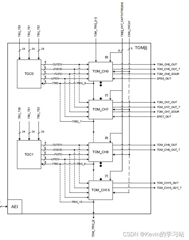
TGC0和TGC1这两个子模块是全局信道控制单元,它们控制信道及其输出的启用/禁用,以及其周期和占空比寄存器的更新。
模块TOM接收两个(三)个时间戳值TBU_TS0、TBU_TS1和TBU_TS2,以实现代表一个公共时间基的同步输出行为。
5个专用时钟线输入CMU_FXCLK提供可选择为输出针时钟的分割时钟。
TOM实例i的触发器信号TOM_TRIG_{i-1]来自于前面的实例i-1,触发器TOM_TRIG_[i]被路由到后续的实例i+1。注意,TOM0连接到它自己的输出TOM_TRIG_0,即TOM实例0的最后一个通道可以触发TOM实例0的第一个通道(该路径被注册,这意味着延迟了一个SYS_CLK周期)。
3、TOM全局通道控制–TGC0, TGC1
存在两个全局信道控制单元(TGC0和TGC1),可以通过外部或内部事件同步驱动多个单独的TOM信道。
每个TGC[y]最多可以驱动8个TOM通道,其中TGC0控制TOM通道0到7,TGC1控制TOM通道8到15。
TOM模块支持四种不同类型的信令机制:
①、具有控制寄存器
TOM[i]_TGC[y]_ENDIS_CTRL和状态寄存器TOM[i]_ TGC[y]_ENDIS_STAT的每个TOM通道的全局启用/禁用机制;②、具有控制寄存器
TOM[i]_TGC[y]_OUTEN_CTRL和状态寄存器TOM[i]_TGC[y]_OUTEN_STAT的每个TOM通道的全局输出启用机制;③、具有控制寄存器
TOM和_TGC和_FUPD_CTRL的每个TOM通道的全局力更新机制;④、使用
TOM[i]_TGC[y]_GLB_CTRL的控制位字段UPEN_CTRL[z]更新每个TOM通道的寄存器CM0、CM1和CLK_SRC。
4、实验简介
4.1、实验目的
通过AURIX TC3X7 通过定时器模块(GTM) 产生 PWM,并调节不同的占空比及脉冲频率。
4.2、TC3X7 GTM 简介
通用计时器模块(GTM)是一个模块化计时器单元,设计以适应许多计时器应用程序;
GTM 有一个内置的定时器输出模块(TOM),可以提供多达16个独立的通道来产生输出信号。
时钟管理单元(CMU)负责GTM的时钟生成。固定时钟生成(FXU)是它的子单元之一,它为GTM模块提供了5个预定义的不可配置的时钟,包括TOM;(TC377有5个时钟源,TC397有8个时钟源:TIM、TBU、MON和ATOM)
4.3、具体配置流程
①、初始化 TOM
TOM的配置是通过调用初始化函数initGtmTomPwm()来完成的,具体包括以下步骤:
①、通过调用函数
IfxGtm_enable()来启用GTM;②、通过调用函数
IfxGtm_Cmu_enableClocks()来启用FXU时钟。
函数IfxGtm_Tom_Pwm_initConfig()用初始化结构IfxGtm_Tom_Pwm_Config;通过修改IfxGtm_Tom_Pwm_Config 结构体,设置以下参数来初始化模块:
tom:选择正在计数的TOM;
tomChannel:选择驱动GPIO的通道;
period:将PWM信号的周期设置为期望的值;
pin.outputPin:选择 GPIO 作为输出引脚;
synchronousUpdateEnable:启用计时器的同步更新。
配置完成后,函数IfxGtm_Tom_Pwm_init()通过用户配置初始化并激活TOM。
②、启动 PWM
使用函数IfxGtm_Tom_Pwm_start()启动PWM。
s暗、设置占空比
占空比的设置是通过调用函数集dutyCycle()来完成的,它包含以下步骤:
①、设置配置结构的双数循环参数,将PWM信号的占空比设置为所需值;
②、调用函数
IfxGtm_Tom_Pwm_init(),用占空比的新值重新配置TOM。
5、具体实现
5.1、Cpu0_Main.c
#include "Ifx_Types.h"
#include "IfxCpu.h"
#include "IfxScuWdt.h"
#include "TOM_PWM.h"
#include "Bsp.h"


#define WAIT_TIME   10              // Number of milliseconds to wait between each duty cycle change

IFX_ALIGN(4) IfxCpu_syncEvent g_cpuSyncEvent = 0;

void core0_main(void)
{
    IfxCpu_enableInterrupts();

    /* !!WATCHDOG0 AND SAFETY WATCHDOG ARE DISABLED HERE!!
     * Enable the watchdogs and service them periodically if it is required
     */
    IfxScuWdt_disableCpuWatchdog(IfxScuWdt_getCpuWatchdogPassword());
    IfxScuWdt_disableSafetyWatchdog(IfxScuWdt_getSafetyWatchdogPassword());


    /* Wait for CPU sync event */
    IfxCpu_emitEvent(&g_cpuSyncEvent);
    IfxCpu_waitEvent(&g_cpuSyncEvent, 1);

    /* Initialize a time variable */
    Ifx_TickTime ticksFor10ms = IfxStm_getTicksFromMilliseconds(BSP_DEFAULT_TIMER, WAIT_TIME);

    /* Initialize GTM TOM module */
    initGtmTomPwm();

    while(1)
    {
        fadeLED();                  /* Change the intensity of the LED  */
        waitTime(ticksFor10ms);     /* Delay of 10ms                    */
    }
}
5.2、TOM_PWM.C
/*
 * TOM_PWM.c
 *
 *  Created on: 2022年12月12日
 *      Author: xstoolbox
 */

#include "TOM_PWM.h"
#include "Ifx_Types.h"
#include "IfxGtm_Tom_Pwm.h"


#define ISR_PRIORITY_TOM    20                                      /* Interrupt priority number                    */
#define LED                 IfxGtm_TOM0_2N_TOUT5_P02_5_OUT          /* LED which will be driven by the PWM          */
#define LED1                IfxGtm_TOM0_7_TOUT6_P02_6_OUT          /* LED which will be driven by the PWM          */
#define PWM_PERIOD          50000                                   /* PWM period for the TOM                       */
#define FADE_STEP           PWM_PERIOD / 100                        /* PWM duty cycle for the TOM                   */


IfxGtm_Tom_Pwm_Config g_tomConfig;                                  /* Timer configuration structure                */
IfxGtm_Tom_Pwm_Config g_tomConfig1;                                  /* Timer configuration structure                */
IfxGtm_Tom_Pwm_Driver g_tomDriver;                                  /* Timer Driver structure                       */
uint32 g_fadeValue = 0;                                             /* Fade value, starting from 0                  */
sint8 g_fadeDir = 1;                                                /* Fade direction variable                      */


void setDutyCycle(uint32 dutyCycle);                                /* Function to set the duty cycle of the PWM    */


void initGtmTomPwm(void)
{
    IfxGtm_enable(&MODULE_GTM);                                     /* Enable GTM                                   */

    IfxGtm_Cmu_enableClocks(&MODULE_GTM, IFXGTM_CMU_CLKEN_FXCLK);   /* Enable the FXU clock                         */

    /* Initialize the configuration structure with default parameters */
    IfxGtm_Tom_Pwm_initConfig(&g_tomConfig, &MODULE_GTM);
    IfxGtm_Tom_Pwm_initConfig(&g_tomConfig1, &MODULE_GTM);


    g_tomConfig.tom = LED.tom;                                      /* Select the TOM depending on the LED          */
    g_tomConfig.tomChannel = LED.channel;                           /* Select the channel depending on the LED      */
    g_tomConfig.period = PWM_PERIOD;                                /* Set the timer period                         */
    g_tomConfig.pin.outputPin = &LED;                               /* Set the LED port pin as output               */
    g_tomConfig.synchronousUpdateEnabled = TRUE;                    /* Enable synchronous update                    */

    g_tomConfig1.tom = LED1.tom;                                      /* Select the TOM depending on the LED          */
    g_tomConfig1.tomChannel = LED1.channel;                           /* Select the channel depending on the LED      */
    g_tomConfig1.period = PWM_PERIOD;                                /* Set the timer period                         */
    g_tomConfig1.pin.outputPin = &LED1;                               /* Set the LED port pin as output               */
    g_tomConfig1.synchronousUpdateEnabled = TRUE;                    /* Enable synchronous update                    */

    IfxGtm_Tom_Pwm_init(&g_tomDriver, &g_tomConfig);                /* Initialize the GTM TOM                       */
    IfxGtm_Tom_Pwm_init(&g_tomDriver, &g_tomConfig1);                /* Initialize the GTM TOM                       */
    IfxGtm_Tom_Pwm_start(&g_tomDriver, TRUE);                       /* Start the PWM                                */
}


void fadeLED(void)
{
setDutyCycle(25000);                                      /* Set the duty cycle of the PWM  */
}

/* This function sets the duty cycle of the PWM */
void setDutyCycle(uint32 dutyCycle)
{
    g_tomConfig.dutyCycle = dutyCycle;                              /* Change the value of the duty cycle  */
    g_tomConfig1.dutyCycle = dutyCycle;                              /* Change the value of the duty  cycle  */
    IfxGtm_Tom_Pwm_init(&g_tomDriver, &g_tomConfig);                /* Re-initialize the PWM */
    IfxGtm_Tom_Pwm_init(&g_tomDriver, &g_tomConfig1);                /* Re-initialize the PWM */
}
5.3、TOM_PWM.h
/*
 * TOM_PWM.h
 *
 *  Created on: 2022年12月12日
 *      Author: xstoolbox
 */

#ifndef TOM_PWM_H_
#define TOM_PWM_H_

void initGtmTomPwm(void);
void fadeLED(void);


#endif /* TOM_PWM_H_ */
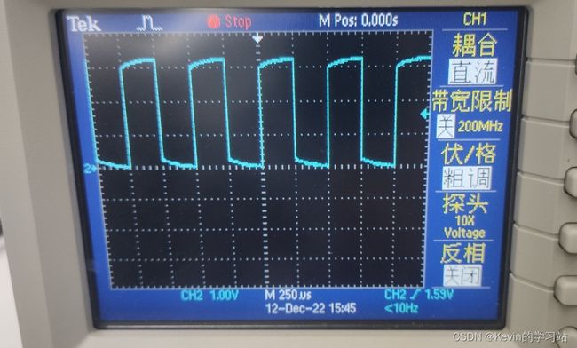
实验结果
生成一个频率为:4KHzs 占空比为50% 的PWM波。

