论文阅读_InP-Based_Generic_Foundry_Platform_for_Photonic_Integrated_Circuits
InP-Based_Generic_Foundry_Platform_for_Photonic_Integrated_Circuits
时间:2018年
作者:Luc M. Augustin, Member, IEEE, Rui Santos, Erik den Haan, Steven Kleijn, Peter J. A. Thijs, Sylwester Latkowski, Senior Member, IEEE, Dan Zhao, Weiming Yao, Jeroen Bolk, Huub Ambrosius, Sergei Mingaleev, Andr´eRichter, Senior Member, IEEE, Arjen Bakker, and Twan Korthorst
Abstract
Abstract—The standardization of photonic integration processes for InP has led to versatile and easily accessible generic integration platforms. The generic integration platforms enable the realization of a broad range of applications and lead to a dramatic cost reduction in the development costs of photonic integrated circuits (PICs). This paper addresses the SMART Photonics generic integration platform developments. The integration technology based on butt joint active-passive epitaxy is shown to achieve a platform without compromising the performance of the different components. The individual components or building blocks are described. A process design kit is established with a comprehensive dataset of simulation and layout information for the building blocks. Latest results on process development and optimization are demonstrated. A big step forward is achieved by applying high-resolution ArF lithography, which leads to increased performance for AWGs and a large increase in reproducibility and yield. The generic nature of the platform is demonstrated by analyzing a number of commercial multiproject wafer runs. It is clear that a large variety of applications is addressed with more than 200 designs from industry as well as academia. A number of examples of PICs are displayed to support this. Finally, the design flow is explained, with focus on layout-aware schematic-driven design flow that is required for complex circuits. It can be concluded that generic integration on InP is maturing fast and with the current developments and infrastructure it is the technology of choice for low cost, densely integrated PICs, ready for high-volume manufacturing.
本片文章介绍Smart Photonics通用集成光学制造平台(欧洲的一家做集成光芯片的公司)的发展。
-
第二节
- 对独立元件和模块进行了描述,建立了一个包含设计模块(building blocks)的仿真模型和版图的PDK
- 讲述了最新的开发与操作流程(基于有源-无源尾部外延生长对接(butt joint active-passive epitaxy)的集成技术可以在集成不同器件时不损失性能)
- 通过更高分辨率的ArF光刻技术,提升了波导光栅阵列(AWG)的性能及其产量
-
第三节
- 该平台的商业生产证明了该平台的通用性
-
第四节
- 解释了集成光芯片的设计流程
InP通用集成技术正在迅速成熟,借助当前的发展和基础设施,它是低成本、高密度集成PIC技术,为大规模生产做好了准备。
一、INTRODUCTION
关于InP集成光芯片:
- 基于InP的光子器件可以同时实现有源/无源器件,因此省去了高精度装配的过程
- 该技术可以实现放大器、激光器、高性能调制器、宽带光电探测器(C~L波段)
- 由于源和探测器可以集成在芯片上,因此可以直接在晶圆上做测试
- 当前的PIC通用集成技术使其成本低廉
关于光子通用集成平台:
- 集成光芯片的基本模块是:波导、放大器、探测器、相位调制器
- 通用集成的优点:
- 采用标准化的工业集成流程,实现了稳定、可重复的性能
- 由于基本模块已定义,因此可以有PDK和设计软件辅助进行快速准确的芯片设计
- 用户可以在MPW(Multi-Project Wafer)模式下分摊成本
- 由于设计、生产成本降低,集成光芯片更易于走向企业
二、TECHNOLOGY AND BUILDING BLOCKS
本节描述了:
- Integration Process
- Current Available Building Blocks
- The Development of Building Blocks
- Enhancement to the Platform
A. 集成流程(Integration Process)
平台采用对接技术(butt-joint technology)的优点:
- 可以将不同性能的材料集成在一起而不影响性能
- 可以将芯片上的有源/无源器件独立进行性能优化
- 有源元件可以放置在任意位置
- 有源-无源元件间的耦合损耗很低(~0.1dB),反射很低(<40dB)
- 因为反射很低,所以可以实现 Ⅲ-B 族激光器
对接技术(butt-joint technology)流程:
图1展示了对接技术(butt-joint technology)
-
首先使用金属有机化学气相沉积(MOCVD)生长活性层(a)
目前的有源层由4个量子阱(QW)组成,发射波长为1550 nm
-
波导层(通常是块状无源波导)通过高质量的对接技术重新生长
-
DBR光栅可以在无源波导的顶部绘制,可以采用电子束光刻,也可以采用更高精度的ArF光刻
光栅被蚀刻成一个单独的光栅层,整个晶圆被一个共同的顶部包层覆盖。生长过后晶圆就可以进行进一步的加工了
图2所示是各模块(Building Blocks)的剖面图
图3所示为流程的示意图概述,显示不同应用优化的工艺流程的不同取向或选项。外延生长步骤以灰色表示,加工步骤以白色表示。
B. Building Blocks & PDK
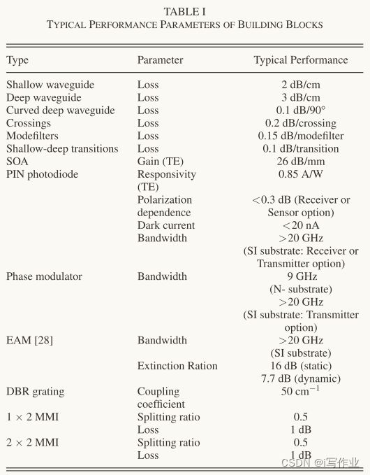
表1总结了基本的模块(Building Blocks)及其性能
除了基本性能参数之外,还有一个可能会严重影响电路性能的附加参数——残余反射(Residual Reflection):
- 对于基础元件,其残余反射已经进行了优化
- 不同波导之间的过渡、对接接头的残余反射远 小于 -40dB
- 交叉点处的残余反射接近 -50dB
- 此外,多模干涉(MMI)耦合器经过优化,以实现如1×2 MMI那样低至 -34dB 的反射
C. Optimization and Enhancement
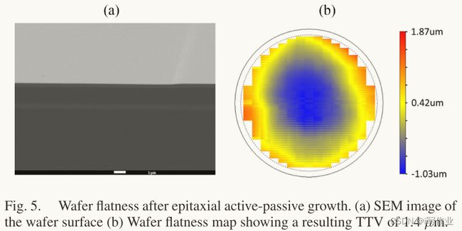
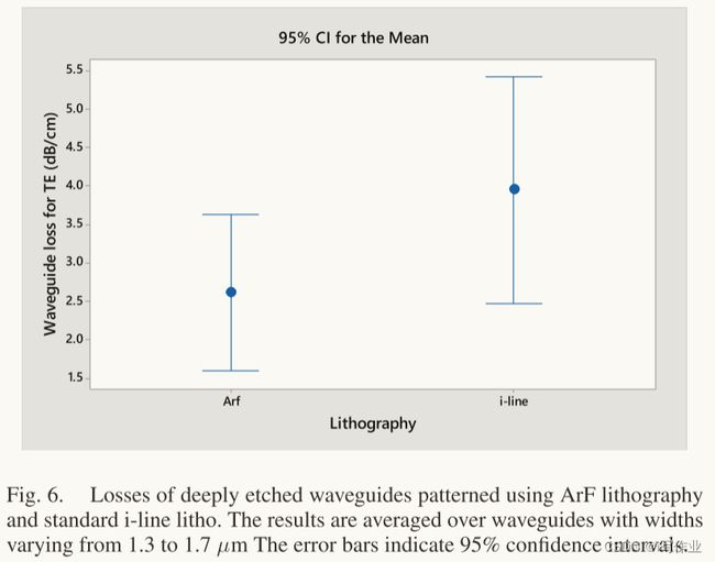
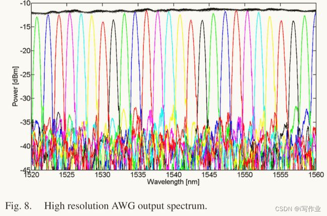
通过更高分辨率的ArF光刻技术,提升了制造平台的性能
-
高分辨率光刻:ASML PAS5500/1100 ArF光刻机,可以用于 3 inch 和 4 inch 晶圆,但其聚焦深度为±150nm。
-
DBR光栅:首次将ArF光刻技术应用于InP晶圆上制作Distributed Feedback Reflector (DBR)光栅
电子束光刻技术存在写入面积有限、耗时长等缺点,而全息光刻技术局限于在大片晶圆上实现光栅图案特性,限制了PIC中不同波长选择的设计自由。ArF光刻结合了这种设计的自由度和高通量。
三、MPW(Multi-Project Wafer)Runs
A. MPW用户分析
B. ASPIC 举例
- Widely Tunable Monolithically Integrated Laser
宽可调单片集成激光器 - On-Chip 2.5 GHz Mode-Locked Laser
片上2.5GHz锁模激光器 - 180 Gbit/s WDM Transmitter
180Gbps波分复用发射机
四、SOFTWARE AND DESIGN FLOW
各种软件套件提供对PDK的访问,并提供一种集成的自上而下的设计流程,支持在平台上快速实现电路的实现。
在PDK中提供了参数化紧凑模型以及所需的掩膜层和布局信息,供电路模拟器和布局工具使用。设计流程使工程师能够使用全面的参数化光子构建模块库功能性地设计PIC。仿真工具为大规模PIC设计提供了可扩展的时间和频率域框架,用于快速准确地建模。
该实施使得可以以自动化方式扫描和优化参数,甚至在与布局相关的参数上进行,从而可以彻底研究对制造容忍度的灵敏度,因此,可以分析最佳设计性能。
五、CONCLUSION
这篇论文展示了通用集成平台的功能。大量的设计和广泛的应用领域证明了该平台的多功能性。高密度集成是可行的,目前的平台容量可以实现10Gb/mm2的密度。高分辨率光刻技术的引入使得可重复和可扩展的工艺成为可能。通过MPW运行的低成本访问与良好的设计工具的可用性相结合,为更广泛的用户群体开启了通用平台的门户。
ICP:Inductively Coupled Plasma 电感耦合等离子体
是一种通过随时间变化的磁场电磁感应产生电流作为能量来源的等离子体源


