Mesh Algorithm in OpenCascade
Mesh Algorithm in OpenCascade
Abstract. Rendering a generic surface is a two steps process: first, computing the points that will form the mesh of the surface and then, send this mesh to 3D API. Use the Triangle to triangulate the parametric space and then lifting map to the model 3D space. This is the main method to visualize the generic shaded surface. This paper show the OpenCascade triangulation of the parametric space and the map result: mesh in 3D model space. Use the method can visualize a generic surface.
Key words. Delaunay Triangulation, Tessellation, Mesh, OpenCascade, Shaded Surface
1. Introduction
与曲线的可视化算法相比,曲面的可视化要稍微复杂点。总的思路还是很好理解的,那就是把参数空间三角剖分,再将剖分结果映射到三维空间,就得到曲面的网格数据了。
因为B样条曲面的强凸包性,所以可以对其参数空间进行三角剖分,再映射到三维空间。这样可以实现曲面的可视化,但是还有些问题需要处理,如曲面上开孔、曲面离散精度控制等。
因为OpenCascade使用了边界表示法(BRep),所以通过Face,Wire,Edge可以得到曲面的参数范围,若曲面上有开孔,也可通过Edge的PCurve得到开孔在曲面上的参数表示。将得到的参数空间进行三角剖分,再映射到三维空间中,即可对边界表示的形状进行可视化。
用三角网格来逼近实际的形状的精度可以通过增加或减少参数空间中的点来实现。当把参数空间剖分得密,映射到三维空间中的曲面更逼近真实的曲面;当把参数空间剖分得疏,映射到三维空间中的曲面就比较粗糙了。
本文主要将OpenCascade中曲面的参数空间的三角剖分结果显示出来,来分析和理解上述算法。
2. OpenCascade BRep Shape
在OpenCascade中实体的边界表示法(BRep)为:
u COMPSOLID由面共享的SOLID组成;
u SOLID(Cylinder, Cone, Sphere, Torus, etc.)由SHELLS分隔出来的体(Volume);
u SHELL由边Edges相连的FACES组成;
u FACE是一个映射(MAP),从矩形的参数UV空间映射到3D空间。(Cylinder: [0, 2*PI] x[0, H] -> R3,Cone, Sphere, Torus, Bezier Surface, NURBS Surface, etc.)
u FACE的边界由WIRE组成;
u WIRE由相连的EDGES组成;
u EDGE也是一个映射,从一维参数空间U映射到3D空间。(Bezier’s Curve: [0,1] -> R3, NURBS Curve, etc.)
u VERTEX是用来限制EDGE的;
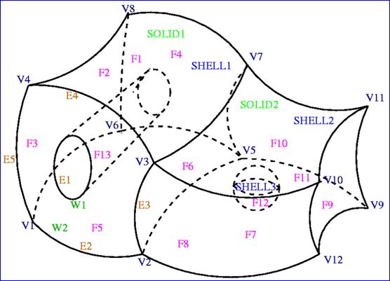
边界表示法(BRep)形成了不同SHAPES(CompSolid, Solid, Shell, Face, Wire, Edge, Vertex)之间的一个图结构(a structure of GRAPH),如下图所示:
Figure 2.1 Shape BRep in OpenCascade
表示上图的的边界表示法形成的树形结构如下图所示。由图可知,有些结构被共享几次。在OpenCascade中使用类TopoDS_Shape来保存这个结构。
Figure 2.2 Graph structure of the BRep Shape
3. How the Mesh is Generated
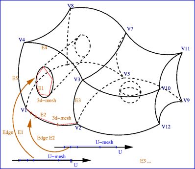
OpenCascade中可以遍历COMPSOLID不同的子形状。首先,将EDGE离散化,实现的伪代码如下所示:
for (TopExp_Explorer edgeExp(theCompSolid, TopAbs_EDGE);
    edgeExp.More();
    edgeExp.Next())
{
    // The U-interval of the EDGE is subdivided into
    // segments with respect to the edge length and
    // deflection in 3D-space. By the map, the segments
    // of the U-interval give the segments in 3D-Space.
    const TopoDS_Edge& theEdge = TopoDS::Edge(edgeExp.Current());
    BRepAdaptor_Curve BAC(theEdge);

    GCPnts_TangentialDeflection thePointsOnCurve;
    thePointsOnCurve.Initialize(BAC, aDeflection, cDeflection);
    Standard_Real u = 0.0;
    gp_Pnt aPoint;
    for (Standard_Integer i = 1; i <= thePointsOnCurve.NbPoints(); ++i)
    {
        u = thePointsOnCurve.Parameter(i);
        aPoint = thePointsOnCurve.Value(i);
    }
}
使用上述算法将每条EDGE离散化,如下图所示:
Figure 3.1 Creation of U-Mesh and 3D-Mesh for each EDGE
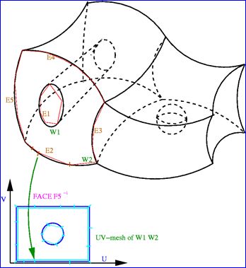
当曲面上有开孔时,开孔的信息可以通过WIRE来获得。对于组成开孔的WIRE的每条EDGE,可以通过曲面上的曲线PCurve来将开孔的参数统一到曲面的UV参数空间。实现的伪代码如下所示:
for (TopExp_Explorer faceExp(theCompSolid, TopAbs_FACE);
    faceExp.More();
    faceExp.Next())
{
    for (TopExp_Explorer wireExp(faceExp.Current(), TopAbs_WIRE);
        wireExp.More();
        wireExp.Next())
    {
        for (TopExp_Explorer edgeExp(wireExp.Current(), TopAbs_EDGE);
            edgeExp.More();
            edgeExp.Next())
        {
            // The U-Mesh of the EDGE is assembled after scaling in the
            // UV-domain to constitute the WIRE.
            Standard_Real theFirst = 0.0;
            Standard_Real theLast = 0.0;
            gp_Pnt2d theUV;

            Handle_Geom2d_Curve thePCurve =
                BRep_Tool::CurveOnSurface(theEdge, theFace, theFirst, theLast);

            theUV = thePCurve.Value(theFirst);
        }
    }
}
Figure 3.2 Hole in Parametric UV space
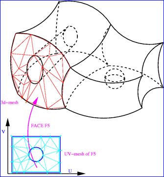
将WIRE限制的曲面的参数空间UV进行三角剖分,若其中有开孔的信息,则将形成孔的WIRE内部的三角形去掉。将参数空间的三角剖分映射到三维空间,即可得到曲面的三角剖分网格。如下图所示:
Figure 3.3 Hole in Surface
对组成COMPSOLID的每个FACE进行剖分,最后就得到COMPSOLID的网格。实现的伪代码如下所示:
for (TopExp_Explorer faceExp(theCompSolid, TopAbs_FACE);
    faceExp.More();
    faceExp.Next())
{
    // The 3d-mesh of the FACE is assembled to form the
    // boundary of the SOLID.
}
Figure 3.4 Mesh of the Shape
4. Deflection Control
形状通过三角网格来逼近显示,所以当离散精度越高时,显示越逼真,但是产生的数据量大;离散精度越低时,显示越失真,但是产生的数据量小。正如莎翁所说:To be or not to be: that is the question。面对选择时,不走极端,中庸之道也是个不错的解决方法。在显示逼真程度与数据量的大小之间做个平衡,实体三角剖分的算法需要考虑的地方。
在OpenCascade中曲面的三角剖分的网格数据都保存在类Poly_Triangulation中,也包括曲面的参数空间的剖分,参数结点数据是UVNodes。如下代码所示为将曲面的参数空间三角剖分结果可视化:
osg::Geode* BuildUVMesh(const Handle_Poly_Triangulation& theMesh)
{
    osg::ref_ptr<osg::Geode> theGeode = new osg::Geode();
    osg::ref_ptr<osg::Geometry> theTriangles = new osg::Geometry();
    osg::ref_ptr<osg::Vec3Array> theVertices = new osg::Vec3Array();

    for (Standard_Integer t = 1; t <= theMesh->NbTriangles(); ++t)
    {
        const Poly_Triangle& theTriangle = theMesh->Triangles().Value(t);

        gp_Pnt2d theUV1 = theMesh->UVNodes().Value(theTriangle(1));
        gp_Pnt2d theUV2 = theMesh->UVNodes().Value(theTriangle(2));
        gp_Pnt2d theUV3 = theMesh->UVNodes().Value(theTriangle(3));

        theVertices->push_back(osg::Vec3(theUV1.X(), 0.0, theUV1.Y()));
        theVertices->push_back(osg::Vec3(theUV2.X(), 0.0, theUV2.Y()));
        theVertices->push_back(osg::Vec3(theUV3.X(), 0.0, theUV3.Y()));
    }

    theTriangles->setVertexArray(theVertices.get());
  theTriangles->addPrimitiveSet(
      new osg::DrawArrays(osg::PrimitiveSet::TRIANGLES, 0, theVertices->size()));

    osgUtil::SmoothingVisitor smv;
    smv.smooth(*theTriangles);

    theGeode->addDrawable(theTriangles);

    return theGeode.release();
}
如下图所示,将球面参数空间的三角剖分显示出来。由球面的参数方程可知其参数空间的范围,U从0到2PI,V从-PI/2到PI/2。
![]()
从图中还可以看出,对球面的参数空间进行剖分时,只在V方向加入了一些点,而在U方向没有增加。
Figure 4.1 Triangulation of the Sphere parametric space
当增加离散精度后,显示得更逼真,但产生了更多的网格数据,如下图所示:
Figure 4.2 Triangulation of the Sphere
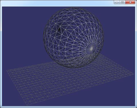
从上图可知,将参数空间剖分的越细密,显示的效果越逼真。由上图还可知,OpenCascade对球面的参数空间剖分也不是很均匀,有很密集的区域,也是相对稀疏的区域。如果将参数空间均匀剖分,映射到三维空间曲面上时,显示效果也不是很均匀。如下图所示为较理想的球面的剖分网格:
Figure 4.3 Triangulation of the Sphere Generated by Netgen
Figure 4.4 Triangulation of the Sphere
从图中可以看出,将参数空间均匀剖分后,映射到三维空间后,在球面的两个极点处,显示出来有些密集,在轨道线附近,比较稀疏。
同一个曲面,当剖分得密集时,显示得细腻,如下图所示:
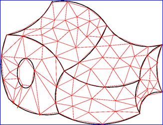
Figure 4.5 Triangulation of a Shape by Netgen
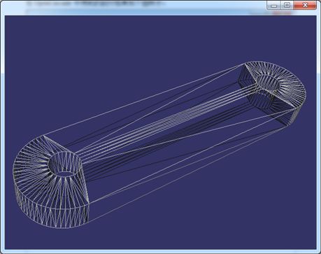
在OpenCascade中得到的剖分结果如下图所示:
Figure 4.6 Triangulation of a Shape by OpenCascade
在OpenCascade中只是把边的离散点组成了三角形,没有优化,但是用于显示也还不错,且数据量也很小。当程序要处理的模型很多时,减少三角网格的数量,将会明显提高显示速度。所以在对实体进行网格剖分时,需要根据实际需要,选择折中的,和谐的算法。即若对网格剖分质量要求较高(如用于有限元分析),模型量少,可以将实体剖分得精细;若模型量很大,又对显示速度要求较高,在网格剖分算法中可以选择产生数据量小的算法。
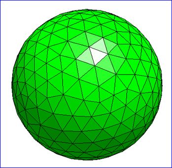
上述形状的渲染模式如下图所示。虽然剖分中也有很多细长的三角形,但当把网格的顶点法向设置正确后,用于显示已经足够。三角形的数量明显要少很多。
Figure 4.7 Shaded mode of the Shape
Figure 4.8 Shaded Mode in OpenCascade
5. Conclusions
将形状中曲面的参数空间三角剖分后,再映射到三维空间即可得到形状的剖分网格。当形状上有开孔时,通过边界表示法,可以得到孔的数据。通过曲面上的曲线PCurve,可将孔与面统一到参数空间进行剖分。
网格的质量与离散精度的控制是个问题。根据需要来对形状进行网格化。当把参数空间均匀剖分时,产生的曲面不一定均匀。所以,也应该存在与曲线离散化类似的算法,即在曲率较大的地方,剖分的密集;在很平的地方,剖分粗。这样来对显示与速度之间做个平衡。
6. References
1. Alain PERRONNET. NEF: A Mesher based on OpenCascade C.A.D software
https://www.ljll.math.upmc.fr/~perronnet/mit/mit.html
2. Kelly Dempski. Focus on Curves and Surfaces. Premier Press 2003
PDF Version: Mesh Algorithm in OpenCascade
