交换机链路聚合
实验二十二、交换机链路聚合
一、 实验目的
1、了解链路聚合技术的使用场合;
2、熟练掌握链路聚合技术的配置。
二、 应用环境
两个实验室分别使用一台交换机提供20 多个信息点,两个实验室的互通通过一根级联
网线。每个实验室的信息点都是百兆到桌面。两个实验室之间的带宽也是100M,如果实验
室之间需要大量传输数据,就会明显感觉带宽资源紧张。当楼层之间大量用户都希望以100M
传输数据的时候,楼层间的链路就呈现出了独木桥的状态,必然造成网络传输效率下降等后
果。
解决这个问题的办法就是提高楼层主交换机之间的连接带宽,实现的办法可以是采用千
兆端口替换原来的 100M 端口进行互联,但这样无疑会增加组网的成本,需要更新端口模块,
并且线缆也需要作进一步的升级。另一种相对经济的升级办法就是链路聚合技术。
顾名思义,链路聚合,是将几个链路作聚合处理,这几个链路必须是同时连接两个相同
的设备的,这样,当作了链路聚合之后就可以实现几个链路相加的带宽了。比如,我们可以
将4 个 100M 链路使用链路聚合作成一个逻辑链路,这样在全双工条件下就可以达到 800M
的带宽,即将近1000M 的带宽。这种方式比较经济,实现也相对容易。
三、 实验设备
1、DCS-3926S 交换机 2 台
2、PC机 2 台
3、Console 线1-2 根
4、直通网线 4-8 根
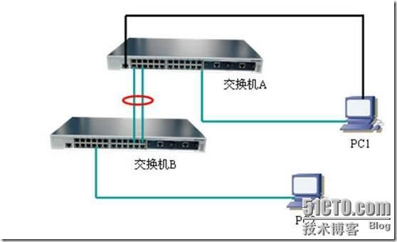
四、 实验拓扑
五、 实验要求
设备 IP Mask 端口
交换机A 192.168.1.11 255.255.255.0 0/0/1-2 trunking
交换机B 192.168.1.12 255.255.255.0 0/0/3-4 trunking
PC1 192.168.1.101 255.255.255.0 交换机A0/0/23
PC2 192.168.1.102 255.255.255.0 交换机B0/0/24
如果链路聚合成功,则PC1 可以ping 通PC2。
六、 实验步骤
第一步:正确连接网线,交换机全部恢复出厂设置,做初始配置,避免广播风暴出现
交换机A:
switch#config
switch(Config)#hostname switchA
switchA(Config)#interface vlan 1
switchA(Config-If-Vlan1)#ip address 192.168.1.11 255.255.255.0
switchA(Config-If-Vlan1)#no shutdown
switchA(Config-If-Vlan1)#exit
switchA(Config)#spanning-tree
MSTP is starting now, please wait...........
MSTP is enabled successfully.
switchA(Config)#
交换机B:
switch#config
switch(Config)#hostname switchB
switchB(Config)#interface vlan 1
switchB(Config-If-Vlan1)#ip address 192.168.1.12 255.255.255.0
switchB(Config-If-Vlan1)#no shutdown
switchB(Config-If-Vlan1)#exit
switchB(Config)#spanning-tree
MSTP is starting now, please wait...........
MSTP is enabled successfully.
switchB(Config)#
第二步:创建port group
交换机A:
switchA(Config)#port-group 1
switchA(Config)#
验证配置:
switchA#show port-group detail
Sorted by the ports in the group 1:
--------------------------------------------
switchA#show port-group brief
Port-group number : 1 Number of ports in port-group : 0 Maxports in port-channel = 8
Number of port-channels : 0 Max port-channels : 1
switchA#
交换机B
switchB(Config)#port-group 2
switchB(Config)#
第三步:手工生成链路聚合组(第三、四步任选其一操作)
交换机A:
switchA(Config)#interface ethernet 0/0/1-2
switchA(Config-Port-Range)#port-group 1 mode on
switchA(Config-Port-Range)#exit
switchA(Config)#interface port-channel 1
switchA(Config-If-Port-Channel1)#
验证配置:
switchA#show vlan
VLAN Name Type Media Ports
---- ------------ ---------- --------- -------------------
1 default Static ENET Ethernet0/0/3 Ethernet0/0/4
Ethernet0/0/5 Ethernet0/0/6
Ethernet0/0/7 Ethernet0/0/8
Ethernet0/0/9 Ethernet0/0/10
Ethernet0/0/11 Ethernet0/0/12
Ethernet0/0/13 Ethernet0/0/14
Ethernet0/0/15 Ethernet0/0/16
Ethernet0/0/17 Ethernet0/0/18
Ethernet0/0/19 Ethernet0/0/20
Ethernet0/0/21 Ethernet0/0/22
Ethernet0/0/23 Ethernet0/0/24
Port-Channel1
switchA# !port-channel1已经存在
交换机B:
switchB(Config)#int e 0/0/3-4
switchB(Config-Port-Range)#port-group 2 mode on
switchB(Config-Port-Range)#exit
switchB(Config)#interface port-channel 2
switchB(Config-If-Port-Channel2)#
验证配置:
switchB#show port-group brief
Port-group number : 2
Number of ports in port-group : 2 Maxports in port-channel = 8
Number of port-channels : 1 Max port-channels : 1
switchB#
第四步: LACP动态生成链路聚合组 (第三、四步任选其一操作)
switchA(Config)#interface ethernet 0/0/1-2
switchA(Conifg-Port-Range)#port-group 1 mode active
switchA(Config)#interface port-channel 1
switchA(Config-If-Port-Channel1)#
验证配置:
switchA#show vlan
VLAN Name Type Media Ports
---- ------------ ---------- --------- -------------------
1 default Static ENET Ethernet0/0/3 Ethernet0/0/4
Ethernet0/0/5 Ethernet0/0/6
Ethernet0/0/7 Ethernet0/0/8
Ethernet0/0/9 Ethernet0/0/10
Ethernet0/0/11 Ethernet0/0/12
Ethernet0/0/13 Ethernet0/0/14
Ethernet0/0/15 Ethernet0/0/16
Ethernet0/0/17 Ethernet0/0/18
Ethernet0/0/19 Ethernet0/0/20
Ethernet0/0/21 Ethernet0/0/22
Ethernet0/0/23 Ethernet0/0/24
Port-Channel1
switchA# !port-channel1已经存在
交换机B:
switchB(Config)#interface ethernet 0/0/3-4
switchB(Conifg-Port-Range)#port-group 2 mode passive
switchB(Config)#interface port-channel 2
switchB(Config-If-Port-Channel2)#
验证配置:
switchB#show port-group brief
Port-group number : 2
Number of ports in port-group : 2 Maxports in port-channel = 8
Number of port-channels : 1 Max port-channels : 1
switchB#
第九步:使用ping命令验证
使用PC1 ping PC2
交换机A 交换机B 结果 原因
0/0/1 0/0/3 通 链路聚合组连接正确
0/0/2 0/0/4
0/0/1 0/0/3 通 拔掉交换机B端口4的网线,仍然可
0/0/2 以通(需要一点时间),此时用show vlan 看看结果,port-channel消
失。只有一个端口连接的时候,没
有必要再维持一个port-channel
了。
0/0/1 0/0/5 通 等候一小段时间后,仍然是通的。
0/0/2 0/0/6 用show vlan看结果。此时把两台交
换机的spanning-tree功能disable
掉,这时候使用第三步和第四步的
结果会不同。采用第四步的,将会
形成环路。
