数字集成电路设计-7-一个简单cpu的设计,实现,仿真与综合
引言
经过对OpenRISC近一年的分析与研究,在此过程中我们了解了计算机体系结构设计相关的主要概念,重要的技术,和基本思想。我觉的,现在我们有必要练练手了。
本小节,我们将设计一个简单的cpu,包括ISA的设计,模块的划分,RTL实现,编写asm汇编程序,用modelsim进行仿真,以及用quartusII的综合。
1,计算器与计算机
我认为,在EDVAC计算机之前的计算机,都可认为是计算器。
原因是,冯诺依曼对EDVAC分析时提出了二进制运算和加入存储部件,而在这之前的计算机是没有存储功能的,比如我们要计算(1+2)&(3+4),如果是采用计算器,其运算步骤如下:
a,先用计算器算出1+2的结果3,然后人脑自己记住这个数。
b,再用计算器计算出3+4的结果7,人脑也自己记住这个数。
c,最后用计算器算出3&7的结果3。
如果采用计算机,其运算过程如下:
首先我们需要写一段程序,假设程序放在程序存储器的地址0x0处,数据1,2,3,4分别放在数据存储器的55,56,57,58四个地址。
程序的执行过程如下:
a,将data_mem的0x55处的数据放到r1。
b,将data_mem的0x56处的数据放到r2。
c,执行add r2,r1,结果放在r2里面。
d,将r2的内容写入到data_mem的0x60这个地址。
e,将data_mem的0x57处的数据放到r3。
f,将data_mem的0x58处的数据放到r4。
g,执行add r4,r3,结果放在r4里面。
h,将r4的内容写入到data_mem的0x61这个地址。
i,将data_mem的0x60处的数据放到r5。
j,将data_mem的0x61处的数据放到r6。
k,执行and r6,r5,结果放在r6里面。
l,将r6的内容写入到data_mem的0x62这个地址,最终得到计算结果。
我们可以看出,如果用计算器计算,只需三步就可以完成,但是如果用计算机的话需要12步才能完成。那是不是用计算机的效率低呢?今天计算机的蓬勃发展使答案不言而喻。
原因就是只要实现写好程序,用计算机的整个计算过程不用人为干预。
我想这正是计算机发展的根本原因之所在,就是计算机的出现是对人的很大解放。我们只要按照一定的方式写好程序,然后交给计算机,计算机会自动完成任务,而我们的手就可以干些其他的事情了!
2,架构设计
1>整体设计
通过上面的例子,我们可以体会到计算机的好处,下面我们就动手设计一个cpu,来完成1+2的计算。
关于计算机体系结构,我们之前说过的内容已经够多了。这里只说明以下几点:
a,我们采用harvard结构,即,指令和数据的总线是独立的。
b,流水线,我们暂时不采用流水设计,但是在最后,我给出了五级流水时的数据通路设计框架。
c,关于指令集,由于是学习目的,我们只实现基本的访存指令,运算指令和分支指令。运算不支持乘除和浮点。关于具体的指令细节,请参考附录。每条指令为16-bit。
d,为了对我们设计的cpu进行仿真和验证,我们需要设计一个简单的soc才行,这个soc只包含指令存储器,cpu内核,数据存储器。
e,core内总线为8-bit。这就有一个问题,core外是8-bit,但是分支指令的目的地址为11-bit,所以如果超过8-bit,就会有问题,暂时还没解决。
下面是soc的整体架构图:我们给他取个名字吧,就叫 tiny_soc,小cpu就简单的称她为tiny_core。
2>模块划分
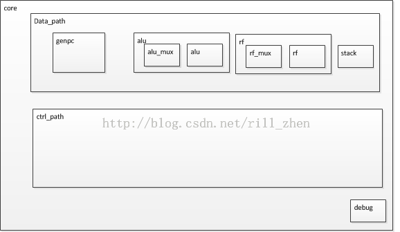
cpu core的结构如下:
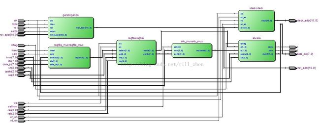
整个cpu core由数据通路和控制通路和调试单元组成。
其中数据通路包括:
PC的产生模块:genpc
运算模块:alu,在alu的前面是对操作数多选一的一个mux。
寄存器堆:regfile模块
还有栈:stack。
数据通路受控制通路模块ctrl_path模块的控制,控制通路负责指令的解码,并产生对应的控制信号。
调试单元,由于只是学习目的,调试单元最简化,只输出当前的PC值和当前的指令内容两个信息。
3,模块划分与接口定义
整体的架构设计完成后,我们就需要进一步的细化了,这时,需要定义具体的模块名称,模块功能,一旦功能确定之后我们就可以确定具体的模块接口信号了。
如果模块功能过大,我们需要拆分成更小的模块,这就是top-down的设计方法。关于设计方法学(top-down,bottom-up),很多资料里都有介绍,这里就不再赘述了。
一个完整的工程,和做理论研究不同,需要处理很多实现细节,下面,我们介绍一下,其中比较重要的部分:
1>genpc模块
这里面需要考虑三点:上电复位PC默认值为多少?正常指令执行时PC如何变化?遇到分支指令时PC如何变化?
关于上电默认值,我们可以通过一个define语句来设定,允许用户后期修改方便。
关于正常指令的指令,PC是加1还是加2还是加4,这要看指令存储器的访问方式,我们的指令存储器是每个地址放一条指令,每条指令是2个字节(16-bit),所以我们只要PC加1就可以了。
关于遇到分支指令,我们直接将控制通路经过解码的跳转地址赋给PC即可。
genpc模块的C语言伪代码如下:
genpc module pseudo code

if(rst)
{
	pc= boot_addr;
}
else
{
	if(branch)
	{
		pc = branch_target;
	}
	else
	{
		pc = pc +1;
	}
}
2>alu模块
alu模块,大家都很熟悉了,是执行单元部件,负责运算指令的运算工作。
这个模块的输入信号是有控制通路的解码出来的操作数和操作码,输出信号就是运算结果。
需要说明的是,这个模块可以完全是组合逻辑电路。
3>rf模块
register file模块,从物理上来说,就是一个block ram。
从逻辑上来说,这个模块是对软件程序员是透明的,寄存器堆和指令集是软件和硬件的交互接口。
4>stack
stack(栈),是用来处理分支指令时,存放PC的值的,比如,我们在处理子程序调用时,需要先将当前的PC+1压栈,等到遇到子程序返回指令时使用。
栈的特点是LIFO(last in first out),这一点与heap(堆)不同。
5>ctrl_path模块
控制通路负责将genpc模块产生的地址处的指令进行解码,并产生对应的操作数,操作码和控制型号。这部分信号比较多一点。
6>tiny_soc
为了测试这个cpu内核,我们需要搭一个最小系统,包括指令只读存储器insn_rom模块,里面存放机器码。
由于是harvard结构,所以还需要一个数据存储器ram模块,相当于内存。
当然,如果想外挂其他I/O外设,我们只需要定义其地址空间即可,需要说明的是I/O外设的地址空间不能与RAM重叠,各个I/O外设之间也不能重叠。
RAM和I/O外设之间可通过一个arbiter与cpu core实现数据交互。
当然,如果存放指令的地方不止一个,也需要一个指令arbiter。
4,RTL实现
在完成模块划分,接口定义,仔细分析考虑模块间时序之后,如果没有什么问题,我们就可以进行编码工作了。
编码,需要注意的是编码一定要规范,信号命名,代码注释什么的,尽量要仔细。这里直接给出RTL代码(verilog HDL)
按照自上而下的顺序依次给出:
1>tiny_soc顶层模块:soc_top
/*
*
* file name	: soc_top.v
* author	: Rill
* date		: 2013-08-11
*
*/

`timescale 1ns / 1ps

module soc_top
(
input clk,
input rst
);


wire  		read_e;
wire  		write_e;
wire [7:0] 	port_addr;
wire [7:0] 	core_in;
wire [7:0] 	core_out;
wire [15:0] instruction;
wire [10:0] inst_addr;

wire [15:0] debug_insn;
wire [10:0] debug_pc;

insn_rom insn_rom
(
.clk (clk),
.rst (rst),
.address (inst_addr),
.instruction (instruction)
);

core core
(
.clk (clk),
.rst (rst),

.read_e (read_e),
.write_e (write_e),
.port_addr (port_addr),
.data_in (core_in),
.data_out (core_out),
.inst_addr (inst_addr),
.instruction (instruction),
.debug_pc (debug_pc),
.debug_insn (debug_insn)
);

ram ram
(
.clk (clk),
.rst (rst),

.wr (write_e),
.rd (read_e),
.addr (port_addr),
.din (core_out),
.dout(core_in)
);


endmodule
2>指令存储器:insn_rom
/*
*
* file name	: insn_rom.v
* author	: Rill
* date		: 2013-08-11
*
*/


module insn_rom
(
input clk,
input rst,
input [10:0] address,
output reg [15:0] instruction
);

//(* RAM_STYLE="BLOCK" *)
reg [15:0] rom [2047:0];

always @(posedge clk)
begin
	if(rst)
		begin
			rom[0] <= 16'h5801;//0:			jmp start
			rom[1] <= 16'h1101;//1:start 	mov r1,1
			rom[2] <= 16'h1202;//2:			mov r2,2
			rom[3] <= 16'h3220;//3:			add r2,r1
			rom[4] <= 16'h2237;//4:			str r2,55
			rom[5] <= 16'h5806;//5:			jmp end
			rom[6] <= 16'h5806;//6:end		jmp end*/
		end
	else
		begin
			instruction <= rom[address];
		end
end


endmodule
3>数据存储器:ram
*
*
* file name	: ram.v
* author	: Rill
* date		: 2013-08-11
*
*/


module ram(
    input clk,
	input rst,

    input [7:0] din,
    input [7:0] addr,
    output reg [7:0] dout,
    input wr,
	input rd
    );

   (* RAM_STYLE="DISTRIBUTED" *)

	reg [7:0] ram [255:0];

   always @(posedge clk)
	begin
		if(rst)
			begin
				dout <= 8'b0;
				ram[0] = 0;
				ram[1] = 1;
				ram[2] = 2;
				ram[32] = 32;
				ram[64] = 64;

			end
		else
			begin
			if (wr)
				ram[addr] <= din;
			else if(rd)
				dout <= ram[addr];
		end
	end

endmodule
4>CPU核心:core
/*
*
* file name	: core.v
* author	: Rill
* date		: 2013-08-11
*
*/


module core
(
    input clk,
    input rst,
    output [7:0] port_addr,
    output read_e,
    output write_e,
    input [7:0] data_in,
    output [7:0] data_out,
	output [10:0] inst_addr,
	input [15:0] instruction,

	output [10:0] debug_pc,//debug i/f
	output [15:0] debug_insn
);

wire z,c;
wire insel;
wire we;
wire [2:0] raa;
wire [2:0] rab;
wire [2:0] wa;
wire [2:0] opalu;
wire [2:0] sh;
wire selpc;
wire ldpc;
wire ldflag;
wire [10:0] ninst_addr;
wire selk;
wire [7:0] KTE;
wire [10:0] stack_addr;
wire wr_en, rd_en;
wire [7:0] imm;
wire selimm;


control_path control_path
(
.clk (clk),
.rst (rst),
.instruction (instruction),
.z (z),
.c (c),
.port_addr (port_addr),
.write_e (write_e),
.read_e (read_e),
.insel (insel),
.we (we),
.raa (raa),
.rab (rab),
.wa (wa),
.opalu (opalu),
.sh (sh),
.selpc (selpc),
.ldpc (ldpc),
.ldflag (ldflag),
.naddress (ninst_addr),
.selk (selk),
.KTE (KTE),
.stack_addr (stack_addr),
.wr_en (wr_en),
.rd_en (rd_en),
.imm (imm),
.selimm (selimm)
);


data_path data_path_i
(
.clk (clk),
.rst (rst),
.data_in (data_in),
.insel (insel),
.we (we),
.raa (raa),
.rab (rab),
.wa (wa),
.opalu (opalu),
.sh (sh),
.selpc (selpc),
.selk (selk),
.ldpc (ldpc),
.ldflag (ldflag),
.wr_en (wr_en),
.rd_en (rd_en),
.ninst_addr (ninst_addr),
.kte (KTE),
.imm (imm),
.selimm (selimm),
.data_out (data_out),
.inst_addr (inst_addr),
.stack_addr (stack_addr),
.z (z),
.c (c)
);

debug debug
(
.pc_in (inst_addr),
.insn_in (instruction),

.pc (debug_pc),
.insn (debug_insn)
);


endmodule
5>调试单元:debug
/*
*
* file name	: debug.v
* author	: Rill
* date		: 2013-08-11
*
*/


module debug
(
input [10:0] pc_in,
input [15:0] insn_in,

output [10:0] pc,
output [15:0] insn
);

assign pc = pc_in;
assign insn = insn_in;

endmodule
6>控制通路:control_path
/*
*
* file name	: control_path.v
* author	: Rill
* date		: 2013-08-11
*
*/


module control_path
(
    input clk,
    input rst,
    input [15:0] instruction,
    input z,
    input c,
    output reg [7:0] port_addr,
    output reg write_e,
    output reg read_e,
    output reg insel,
    output reg we,
    output reg [2:0] raa,
    output reg [2:0] rab,
    output reg [2:0] wa,
    output reg [2:0] opalu,
    output reg [2:0] sh,
    output reg selpc,
    output reg ldpc,
    output reg ldflag,
    output reg [10:0] naddress,
    output reg selk,
    output reg [7:0] KTE,
	input [10:0] stack_addr,
	output reg wr_en, rd_en,
	output reg [7:0] imm,
	output reg selimm
    );


parameter fetch=	5'd0;
parameter decode=	5'd1;

parameter ldi=		5'd2;
parameter ldm=		5'd3;
parameter stm=		5'd4;
parameter cmp=		5'd5;
parameter add=		5'd6;
parameter sub=		5'd7;
parameter andi=		5'd8;
parameter oor=		5'd9;
parameter xori=		5'd10;
parameter jmp=		5'd11;
parameter jpz=		5'd12;
parameter jnz=		5'd13;
parameter jpc=		5'd14;
parameter jnc=		5'd15;
parameter csr=		5'd16;
parameter ret=		5'd17;

parameter adi=		5'd18;
parameter csz=		5'd19;
parameter cnz=		5'd20;
parameter csc=		5'd21;
parameter cnc=		5'd22;
parameter sl0=		5'd23;
parameter sl1=		5'd24;
parameter sr0=		5'd25;
parameter sr1=		5'd26;
parameter rrl=		5'd27;
parameter rrr=		5'd28;
parameter noti=		5'd29;

parameter nop=		5'd30;

wire [4:0] opcode;
reg [4:0] state;

assign opcode=instruction[15:11];

always@(posedge clk or posedge rst)
begin
	if (rst)
		begin
			state<=decode;
		end

	else
		begin
			case (state)
				fetch:
					begin
						state<=decode;
					end

				decode:
					begin
						if(opcode >=ldi && opcode <=nop)
							state <= opcode;//state just is the opcode now
						else
							state <= nop;
					end

				default:
					state<=fetch;
			endcase
		end

end


always@(*)
begin
		port_addr<=0;
		write_e<=0;
		read_e<=0;
		insel<=0;
		we<=0;
		raa<=0;
		rab<=0;
		wa<=0;
		opalu<=4;
		sh<=4;
		selpc<=0;
		ldpc<=1;
		ldflag<=0;
		naddress<=0;
		selk<=0;
		KTE<=0;
		wr_en<=0;
		rd_en<=0;
		imm<=0;
		selimm<=0;

		case (state)
			fetch: 	begin
						ldpc<=0;
					end

			decode: begin
						ldpc<=0;
						if (opcode==stm)
							begin
								raa<=instruction[10:8];
								port_addr<=instruction[7:0];
							end
						else if (opcode==ldm)
							begin
								wa<=instruction[10:8];
								port_addr<=instruction[7:0];
							end
						else if (opcode==ret)
							begin
								rd_en<=1;
							end
					end

			ldi:	begin
						selk<=1;
						KTE<=instruction[7:0];
						we<=1;
						wa<=instruction[10:8];
					end

			ldm:	begin
						wa<=instruction[10:8];
						we<=1;
						read_e<=1;
						port_addr<=instruction[7:0];
					end

			stm:	begin
						raa<=instruction[10:8];
						write_e<=1;
						port_addr<=instruction[7:0];
					end

			cmp:	begin
						ldflag<=1;
						raa<=instruction[10:8];
						rab<=instruction[7:5];
						opalu<=6;
					end

			add:	begin
						raa<=instruction[10:8];
						rab<=instruction[7:5];
						wa<=instruction[10:8];
						insel<=1;
						opalu<=5;
						we<=1;
					end

			sub:	begin
						raa<=instruction[10:8];
						rab<=instruction[7:5];
						wa<=instruction[10:8];
						insel<=1;
						opalu<=6;
						we<=1;
					end

			andi:	begin
						raa<=instruction[10:8];
						rab<=instruction[7:5];
						wa<=instruction[10:8];
						insel<=1;
						opalu<=1;
						we<=1;
					end

			oor:	begin
						raa<=instruction[10:8];
						rab<=instruction[7:5];
						wa<=instruction[10:8];
						insel<=1;
						opalu<=3;
						we<=1;
					end

			xori:	begin
						raa<=instruction[10:8];
						rab<=instruction[7:5];
						wa<=instruction[10:8];
						insel<=1;
						opalu<=2;
						we<=1;
					end

			jmp:	begin
						naddress<=instruction[10:0];
						selpc<=1;
						ldpc<=1;
					end

			jpz:		if (z)
						begin
							naddress<=instruction[10:0];
							selpc<=1;
							ldpc<=1;
						end

			jnz:		if (!z)
							begin
								naddress<=instruction[10:0];
								selpc<=1;
								ldpc<=1;
							end


			jpc:	if (c)
							begin
								naddress<=instruction[10:0];
								selpc<=1;
								ldpc<=1;
							end


			jnc:	if (!c)
							begin
								naddress<=instruction[10:0];
								selpc<=1;
								ldpc<=1;
							end

			csr:	begin
						naddress<=instruction[10:0];
						selpc<=1;
						ldpc<=1;
						wr_en<=1;
					end

			ret:	begin
						naddress<=stack_addr;
						selpc<=1;
						ldpc<=1;
					end

			adi:	begin
						raa<=instruction[10:8];
						wa<=instruction[10:8];
						imm<=instruction[7:0];
						selimm<=1;
						insel<=1;
						opalu<=5;
						we<=1;
					end

			csz:	if (z)
						begin
							naddress<=instruction[10:0];
							selpc<=1;
							ldpc<=1;
							wr_en<=1;
						end

			cnz:	if (!z)
						begin
							naddress<=instruction[10:0];
							selpc<=1;
							ldpc<=1;
							wr_en<=1;
						end

			csc:	if (c)
						begin
							naddress<=instruction[10:0];
							selpc<=1;
							ldpc<=1;
							wr_en<=1;
						end

			cnc:	if (!c)
						begin
							naddress<=instruction[10:0];
							selpc<=1;
							ldpc<=1;
							wr_en<=1;
						end

			sl0:	begin
						raa<=instruction[10:8];
						wa<=instruction[10:8];
						insel<=1;
						sh<=0;
						we<=1;
					end

			sl1:	begin
						raa<=instruction[10:8];
						wa<=instruction[10:8];
						insel<=1;
						sh<=5;
						we<=1;
					end

			sr0:	begin
						raa<=instruction[10:8];
						wa<=instruction[10:8];
						insel<=1;
						sh<=2;
						we<=1;
					end

			sr1:	begin
						raa<=instruction[10:8];
						wa<=instruction[10:8];
						insel<=1;
						sh<=6;
						we<=1;
					end

			rrl:	begin
						raa<=instruction[10:8];
						wa<=instruction[10:8];
						insel<=1;
						sh<=1;
						we<=1;
					end

			rrr:	begin
						raa<=instruction[10:8];
						wa<=instruction[10:8];
						insel<=1;
						sh<=3;
						we<=1;
					end

			noti:	begin
						raa<=instruction[10:8];
						wa<=instruction[10:8];
						insel<=1;
						opalu<=0;
						we<=1;
					end

			nop:	begin
						opalu<=4;
					end
		endcase
end


endmodule
7>数据通路:data_path
/*
*
* file name	: data_path.v
* author	: Rill
* date		: 2013-08-11
*
*/


module data_path
(
    input clk,
    input rst,
    input [7:0] data_in,
    input insel,
    input we,
    input [2:0] raa,
    input [2:0] rab,
    input [2:0] wa,
    input [2:0] opalu,
    input [2:0] sh,
    input selpc,
	input selk,
    input ldpc,
	input ldflag,
	input wr_en, rd_en,
	input [10:0] ninst_addr,
	input [7:0] kte,
	input [7:0] imm,
	input selimm,
    output [7:0] data_out,
    output [10:0] inst_addr,
	output [10:0] stack_addr,
	output  z,c
);

wire [7:0] regmux, muximm;
wire [7:0] portA, portB;

wire [7:0] shiftout;

assign data_out=shiftout;


genpc genpc
(
.clk (clk),
.rst (rst),

.ldpc (ldpc),
.selpc (selpc),
.ninst_addr (ninst_addr),

.inst_addr (inst_addr)
);


alu_mux alu_mux
(
.selimm (selimm),
.imm (imm),
.portB (portB),

.muximm (muximm)
);

alu alu
(
.a (portA),
.b (muximm),
.opalu (opalu),
.ldflag (ldflag),
.zero (z),
.carry (c),
.sh (sh),
.dshift (shiftout)
);


stack stack
(
.clk (clk),
.rst (rst),
.wr_en (wr_en),
.rd_en (rd_en),
.din (inst_addr),
.dout (stack_addr)
);


regfile_mux regfile_mux
(
.insel (insel),
.selk (selk),
.shiftout (shiftout),
.kte (kte),
.data_in (data_in),

.regmux (regmux)
);

regfile regfile
(
.datain (regmux),
.clk (clk),
.we (we),
.wa (wa),
.raa (raa),
.rab (rab),
.porta (portA),
.portb (portB)
);


endmodule
8>程序计算器:genpc
/*
*
* file name	: genpc.v
* author	: Rill
* date		: 2013-08-11
*
*/

`define boot_addr 0     //boot address after power on

module genpc
(
input clk,
input rst,

input ldpc,
input selpc,
input [10:0] ninst_addr,

output [10:0] inst_addr
);

reg [10:0] pc;

assign inst_addr=pc;

always@(posedge clk or posedge rst)
begin
	if (rst)
		pc <=`boot_addr;
	else
		if (ldpc)
			if(selpc)
				pc<=ninst_addr;
			else
				pc<=pc+1;
end


endmodule
9>运算单元:alu ,alu_mux
/*
*
* file name	: alu_mux.v
* author	: Rill
* date		: 2013-08-11
*
*/


module alu_mux
(
input selimm,
input [7:0] imm,
input [7:0] portB,

output [7:0] muximm
);

assign muximm = selimm? imm : portB;//result : imm if ldi insn,portb if ldm insn


endmodule
/*
*
* file name	: alu.v
* author	: Rill
* date		: 2013-08-11
*
*/


module alu
(
input [7:0] a,
input [7:0] b,
input [2:0] opalu,
input ldflag,
output zero,
output carry,
input [2:0] sh,
output reg [7:0] dshift
);

reg [7:0] resu;

assign zero=ldflag?(resu==0):1'b0;

assign carry=ldflag?(a<b):1'b0;

always@(*)
	case (opalu)
		0: resu <= ~a;
		1: resu <= a & b;
		2: resu <= a ^ b;
		3: resu <= a | b;
		4: resu <= a;
		5: resu <= a + b;
		6: resu <= a - b;
		default: resu <= a + 1;
	endcase


always@*
		case (sh)
			0: dshift <= {resu[6:0], 1'b0};
			1: dshift <= {resu[6:0], resu[7]};
			2: dshift <= {1'b0, resu[7:1]};
			3: dshift <= {resu[0], resu[7:1]};
			4: dshift <= resu;
			5: dshift <= {resu[6:0], 1'b1};
			6: dshift <= {1'b1, resu[7:1]};
			default: dshift <= resu;
		endcase

endmodule
10>寄存器堆:regfile,regfile_mux
/*
*
* file name	: regfile_mux.v
* author	: Rill
* date		: 2013-08-11
*
*/


module regfile_mux
(
input insel,
input selk,
input [7:0] shiftout,
input [7:0] kte,
input [7:0] data_in,

output [7:0] regmux
);

wire [7:0] muxkte;

assign regmux=insel? shiftout : muxkte;
assign muxkte=selk? kte : data_in;


endmodule
/*
*
* file name	: regfile.v
* author	: Rill
* date		: 2013-08-11
*
*/


module regfile(
    input [7:0] datain,
    input clk, we,
    input [2:0] wa,
    input [2:0] raa,
    input [2:0] rab,
    output [7:0] porta,
    output [7:0] portb
    );


reg [7:0] mem [7:0];//r0 ~r255

always@(posedge clk)
begin
	mem[0]<=0;//r0 always is 0

	if(we)
		mem[wa]<=datain;
end

assign porta=mem[raa];
assign portb=mem[rab];


endmodule
11>栈:stack
/*
*
* file name	: stack.v
* author	: Rill
* date		: 2013-08-11
*
*/


module stack(
    input clk,
	 input rst,
    input wr_en,
    input rd_en,
    input [10:0] din,
    output [10:0] dout
    );


   (* RAM_STYLE="DISTRIBUTED" *)
reg [3:0] addr;
reg [10:0] ram [15:0];

assign dout = ram[addr] +1;

always@(posedge clk)
begin
	if (rst)
		addr<=0;
	else
		begin
			if (wr_en==0 && rd_en==1)  //leer
				if (addr>0)
					addr<=addr-1;
			if (wr_en==1 && rd_en==0)  //guardar
				if (addr<15)
					addr<=addr+1;
		end
end

always @(posedge clk)
begin
	if (wr_en)
		ram[addr] <= din;
end

endmodule
5,modelsim仿真
1>编写testbench
要进行仿真,需要编写对应的testbench,由于咱们这个cpu很简单,所以测试激励也很简单,代码如下:
/*
*
* file name	: tiny_soc_tb.v
* atthor	: Rill
* date		: 2013-08-11
*
*/

`timescale 1ns / 1ps

module tiny_soc_tb;


reg clk;
reg rst;


always #5 clk = ~clk;

initial
begin
	#0
		clk = 0;
		rst = 0;
	#15
		rst = 1;
	#10
		rst = 0;

	#1000
		$stop;
end

soc_top soc_top
(
.clk (clk),
.rst (rst)
);


endmodule
2>编写汇编代码及手动汇编
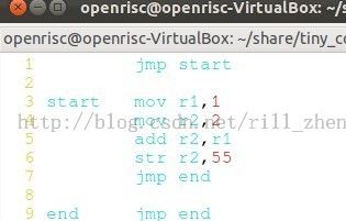
当然还要编写其汇编代码,如下:
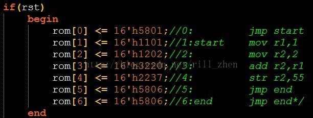
然后我们要手动汇编成机器码,指令集都是自己定义的,所以是没有现成的compiler,只能手动汇编了,还好手动汇编要比手动反汇编轻松多了(之前,我们手动反汇编过OpenRISC的启动代码)。
汇编完成后,我们将机器码放到指令存储器里,如下,共七条指令。
3>仿真结果
完成上面的工作之后,我们就可以用仿真工具进行仿真了,下面是我用modelsim仿真的结果。
从波形可以清晰的看出七条指令的执行过程。在运算完成后拉高write_e信号并将1+2的运算结果3写到了ram地址是55(0x37)的地方。
4>代码仿真覆盖率
由于这个测试汇编代码很短,我们有必要了解一下这个仿真激励运行过程中到底测试了多少代码,下面是code coverage报告截图。
需要说明的是上面的截图并不完整,下面是完整的代码覆盖率报告。
Coverage Report Summary Data by file

File: E:/work/tiny_soc/bench/tiny_soc_tb.v
    Enabled Coverage        Active      Hits % Covered
    ----------------        ------      ---- ---------
    Stmts                       11        11     100.0
    Branches                     0         0     100.0
    Conditions                   0         0     100.0
    Fec Conditions               0         0     100.0
    Expressions                  0         0     100.0
    Fec Expressions              0         0     100.0

File: E:/work/tiny_soc/rtl/core/alu.v
    Enabled Coverage        Active      Hits % Covered
    ----------------        ------      ---- ---------
    Stmts                       20         7      35.0
    Branches                    16         3      18.7
    Conditions                   0         0     100.0
    Fec Conditions               0         0     100.0
    Expressions                  8         2      25.0
    Fec Expressions              8         2      25.0

File: E:/work/tiny_soc/rtl/core/alu_mux.v
    Enabled Coverage        Active      Hits % Covered
    ----------------        ------      ---- ---------
    Stmts                        1         1     100.0
    Branches                     2         1      50.0
    Conditions                   0         0     100.0
    Fec Conditions               0         0     100.0
    Expressions                  0         0     100.0
    Fec Expressions              0         0     100.0

File: E:/work/tiny_soc/rtl/core/control_path.v
    Enabled Coverage        Active      Hits % Covered
    ----------------        ------      ---- ---------
    Stmts                      160        48      30.0
    Branches                    60        18      30.0
    Conditions                   3         1      33.3
    Fec Conditions               4         2      50.0
    Expressions                  0         0     100.0
    Fec Expressions              0         0     100.0

File: E:/work/tiny_soc/rtl/core/genpc.v
    Enabled Coverage        Active      Hits % Covered
    ----------------        ------      ---- ---------
    Stmts                        4         4     100.0
    Branches                     6         6     100.0
    Conditions                   0         0     100.0
    Fec Conditions               0         0     100.0
    Expressions                  0         0     100.0
    Fec Expressions              0         0     100.0

File: E:/work/tiny_soc/rtl/core/regfile.v
    Enabled Coverage        Active      Hits % Covered
    ----------------        ------      ---- ---------
    Stmts                        4         4     100.0
    Branches                     2         2     100.0
    Conditions                   0         0     100.0
    Fec Conditions               0         0     100.0
    Expressions                  0         0     100.0
    Fec Expressions              0         0     100.0

File: E:/work/tiny_soc/rtl/core/regfile_mux.v
    Enabled Coverage        Active      Hits % Covered
    ----------------        ------      ---- ---------
    Stmts                        1         1     100.0
    Branches                     4         4     100.0
    Conditions                   0         0     100.0
    Fec Conditions               0         0     100.0
    Expressions                  0         0     100.0
    Fec Expressions              0         0     100.0

File: E:/work/tiny_soc/rtl/core/stack.v
    Enabled Coverage        Active      Hits % Covered
    ----------------        ------      ---- ---------
    Stmts                        7         4      57.1
    Branches                    12         5      41.6
    Conditions                   6         2      33.3
    Fec Conditions               8         2      25.0
    Expressions                  0         0     100.0
    Fec Expressions              0         0     100.0

File: E:/work/tiny_soc/rtl/insn_rom.v
    Enabled Coverage        Active      Hits % Covered
    ----------------        ------      ---- ---------
    Stmts                        9         9     100.0
    Branches                     2         2     100.0
    Conditions                   0         0     100.0
    Fec Conditions               0         0     100.0
    Expressions                  0         0     100.0
    Fec Expressions              0         0     100.0

File: E:/work/tiny_soc/rtl/ram.v
    Enabled Coverage        Active      Hits % Covered
    ----------------        ------      ---- ---------
    Stmts                        9         8      88.8
    Branches                     6         5      83.3
    Conditions                   0         0     100.0
    Fec Conditions               0         0     100.0
    Expressions                  0         0     100.0
    Fec Expressions              0         0     100.0
6,综合
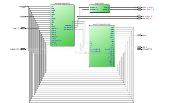
完成了仿真之后,我们就可以综合一下,在FPGA上验证了,下面是我用quartusII 12.0综合的结果。
soc_top模块:
core模块:
data_path模块:
7,改进及优化
咱们设计现在这个小cpu core的目的是为了学习,在于了解cpu内部的运行机制,与软件的交互过程,没有考虑性能,功耗,面积等问题。
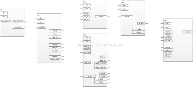
下面,我给出了采用五级流水的数据通路的模块划分和接口定义,如下所示,感兴趣的兄弟可以试着实现她。
8,future work
1,pipeline,将core流水化
2,增加乘法,除法指令。咱们前面介绍过4-bit乘法器和除法器的设计:http://blog.csdn.net/rill_zhen/article/details/9700155
3,fix bug
4,设计tiny_core的assembler,这样就不用手动汇编了。
9,小结
本小节,我们试着设计了一个简单的cpu,并编写了可综合的外部基本模块和不可综合的测试激励模块,然后用quartusII进行了综合,最后还给出了优化后的数据通路结构。
我想,通过本小节的内容,应该对cpu的工作机制和软件与硬件的关系有了更深入的感觉了。
需要说明的是,我的水平有限,再加上时间很短(两周),所以这里面肯定还有很多问题,和需要改进的地方,如果感兴趣,可以把代码down下来,先用modelsim仿真一下,然后再写个I/O controller,比如uart的控制器,挂到数据总线上,如果PC机能收到tiny_soc发出的“hello world”,那是多么令人激动的一件事情啊。
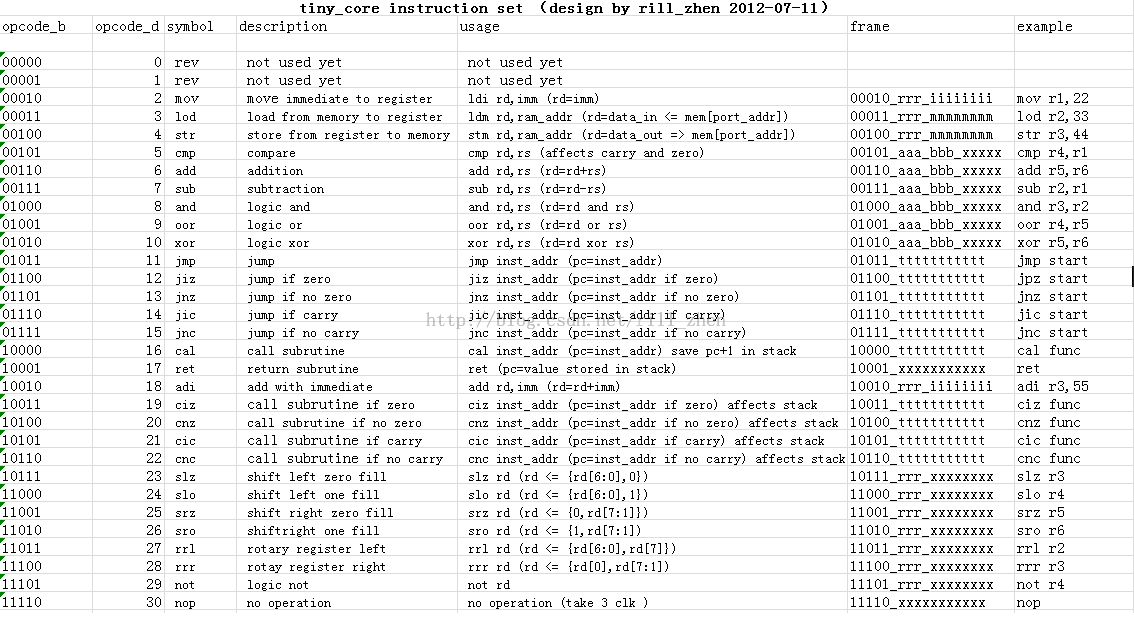
附录:tiny_core的指令集
说明:
rrr:代表寄存器。
aaa和bbb分别代表寄存器A和寄存器B,其中寄存器A是目的寄存器。
iiiiiiii:代表8-bit的立即数。
xxx:代表忽略。
ttt:11 bit的跳转/分支地址。
此外,这个指令集其实很早就开始弄了,最早是去年上半年开始的,现在是最新版本。

