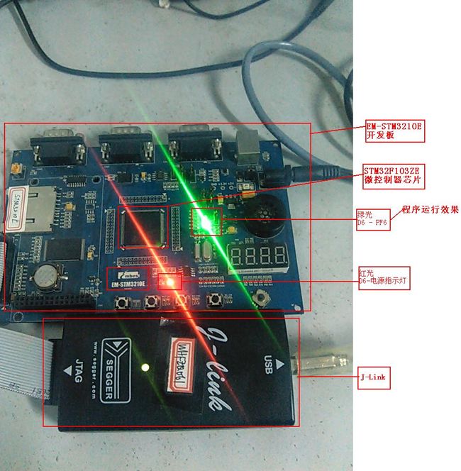
ARM嵌入式编程(无操作系统、基于MDK)之最简单的程序:点亮一个LED灯
1.设计要求
EM-STM3210E开发板上有一个LED灯D1,编写程序点亮该灯。
2.硬件电路连接
在开发板上,D1与STM32F103ZE芯片上的引脚PF6相连,如下图所示。
3.软件程序设计
根据任务要求,程序内容主要包括:
1、配置Reset and clock control (RCC)以使能GPIOF端口模块的时钟
2、配置GPIOF端口的PF6引脚(50MHz,推挽输出)
3、调用STM32标准固件库函数GPIO_WriteBit以令PF6引脚输出高电平,从而点亮LED灯D1。
整个工程用户只需要实现源代码文件:main.c,其他工程文件由MDK和STM32标准固件库提供。
main.c文件的内容如下:
/**
  ******************************************************************************
  * @file    main.c
  * @author  Max Liao
  * @version
  * @date    02-Novenber-2012
  * @brief   Main program body
  ******************************************************************************
  */

/* Includes ------------------------------------------------------------------*/
#include "stm32f10x.h"

/* Private typedef -----------------------------------------------------------*/
/* Private define ------------------------------------------------------------*/
/* Private macro -------------------------------------------------------------*/
/* Private variables ---------------------------------------------------------*/
GPIO_InitTypeDef GPIO_InitStructure;

/* Private function prototypes -----------------------------------------------*/
void RCC_Configuration(void);
void GPIO_Configuration(void);

/* Private functions ---------------------------------------------------------*/

/**
  * @brief  Main program.
  * @param  None
  * @retval None
  */
int main(void)
{
    RCC_Configuration();
    GPIO_Configuration();

    /* PF6引脚输出高电平,点亮EM-STM3210E开发板上的LED灯D1 */
    GPIO_WriteBit(GPIOF, GPIO_Pin_6, Bit_SET);

    /* Infinite loop */
    while (1) {
    }
}


void RCC_Configuration(void)
{
    RCC_APB2PeriphClockCmd(RCC_APB2Periph_GPIOF, ENABLE);
}

void GPIO_Configuration(void)
{
  GPIO_InitStructure.GPIO_Pin = GPIO_Pin_6;
  GPIO_InitStructure.GPIO_Speed = GPIO_Speed_50MHz;
  GPIO_InitStructure.GPIO_Mode = GPIO_Mode_Out_PP;    // 推挽输出
  GPIO_Init(GPIOF, &GPIO_InitStructure);
}
4.程序运行效果

