Zynq开发板使用记录
文章目录
- Zynq基础知识
- 时钟域
- 中断
- 定时器
- AXI HP/GP/ACP接口
- AXI_HP interfaces
- AXI_GP interfaces
- AXI_ACP Interface
- AXI DMA
- Direct Register Mode
- Direct Register Mode Register Address Map
- Scatter / Gather Mode
- Scatter / Gather Mode Register Address Map
- Scatter Gather Descriptor
- A DMA operation for the MM2S channel
- A DMA operation for the S2MM channel
- Zynq工程建立
- 器件信息
- 器件的PL部分XDC约束
- 建立PS核
- DDR3配置
- MIO配置
- PL开发
- 串口测试
- Zynq固化
- 测试工程
- 参考博文链接
- 使用FreeRTOS
- FreeRTOS使用GPIO中断
- 将FreeRTOS源码包含到工程中
- 使用FreeRTOS_CLI
- 解析串口数据包
- 参考博文链接
- 使用FreeRTOS_PLUS_TCP
- 参考博文链接
- SD卡读写
- 使用FatFs_0.14
- PS在线配置PL
- 方式1:借鉴FSBL
- 方式2:采用xdevcfg_polled_example
- 参考博文链接
- AXI_DMA简单使用
- 使用Direct Register Mode
- 测试一
- 测试二
- 测试三
- 参考博文链接
- 使用Scatter/Gather Mode
- 测试一
- 测试二
- 参考博文链接
- PetaLinux
- 安装
- 设计流程
- 初次使用
- 参考博文链接
- SDK调试Linux app
- 其他
- 修改BSP设置后,源代码中的宏定义值使用异常
Zynq基础知识
先上图,常看常新。

时钟域
20200312
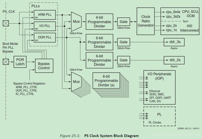
各个时钟之间有两组比例关系,6:3:2:1和4:2:2:1。CPU_6x时钟域主要用作CPU时钟,CPU互连和OCM仲裁;CPU_2x时钟域主要用作L2Cache,I/O外设的AXI互连和OCM RAM;CPU_1x时钟域主要用作I/O外设的AHB和APB总线互连;DDR_3x时钟域主要用作DDR存储控制器;DDR_2x时钟域主要用作访问PL(AXI_HP{0:3})的高性能的AXI总线互连。手册中给出的范例如下,

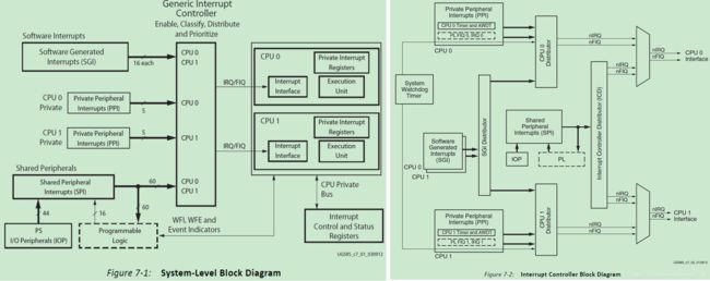
中断
20200312

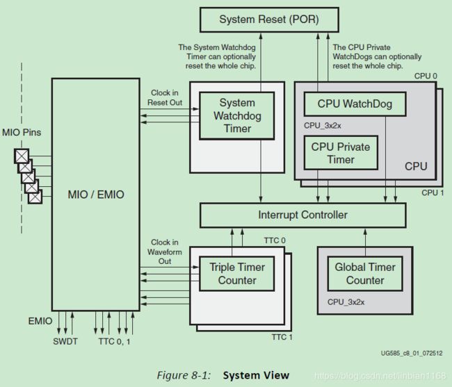
定时器
20200312
AXI HP/GP/ACP接口
20200315
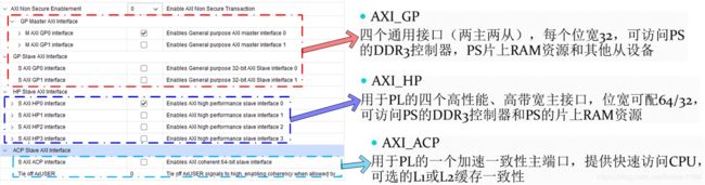
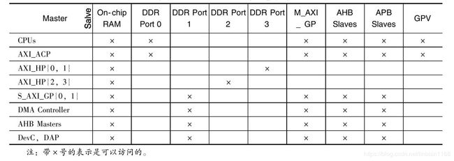
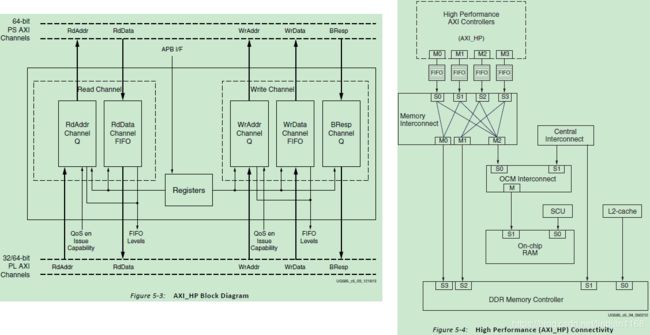
AXI_HP interfaces
- 每个接口都包括两个FIFO缓冲
- 为PL提供了访问DDR和OCM的高带宽路径
The four AXI_HP interfaces provide PL bus masters with high bandwidth datapaths to the DDR and OCM memories. Each interface includes two FIFO buffers for read and write traffic. The PL to memory interconnect routes the high-speed AXI_HP ports to two DDR memory ports or the OCM. The AXI_HP interfaces are also referenced as AFI (AXI FIFO interface), to emphasize their buffering capabilities. The PL level shifters must be enabled through LVL_SHFTR_EN before PL logic communication can occur.
AXI_GP interfaces
These interfaces are connected directly to the ports of the master interconnect and the slave interconnect, without any additional FIFO buffering, unlike the AXI_HP interfaces which has elaborate FIFO buffering to increase performance and throughput. Therefore, the performance is constrained by the ports of the master interconnect and the slave interconnect. These interfaces are for general-purpose use only and are not intended to achieve high performance
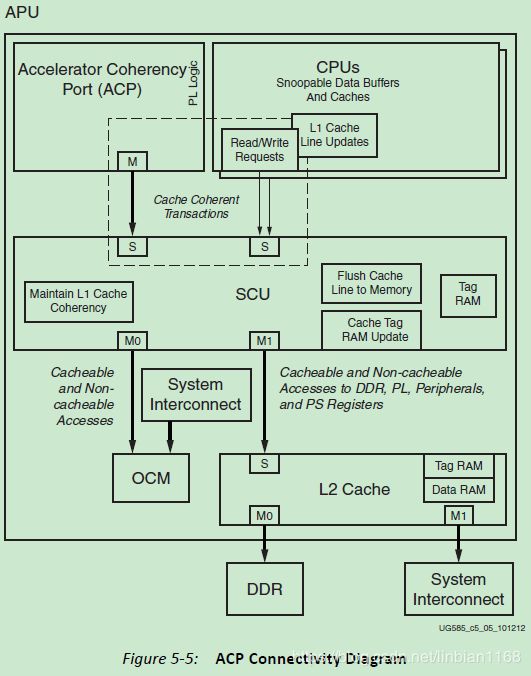
AXI_ACP Interface
The accelerator coherency port provides low-latency access to programmable logic masters, with optional coherency with L1 and L2 cache. From a system perspective, the ACP interface has similar connectivity as the APU CPUs. Due to this close connectivity, the ACP directly competes with them for resource access outside of the APU block
AXI DMA
20200314
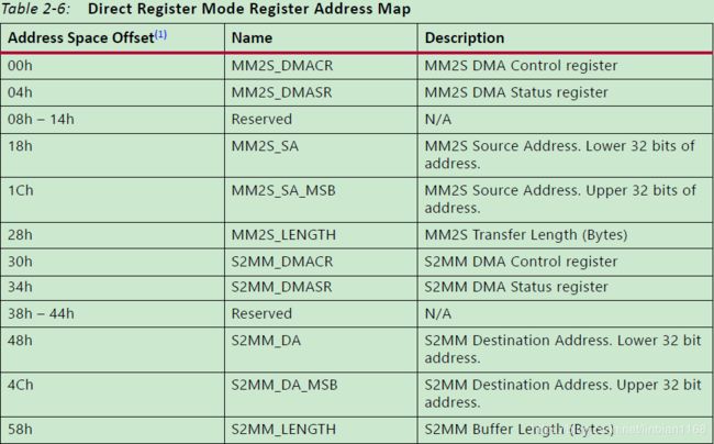
Direct Register Mode
Direct Register Mode Register Address Map
Scatter / Gather Mode
Direct Register Mode一次访问一个内存空间,在每次传输结束后中断通知CPU,增加了CPU 的负担,效率较低,而Scatter / Gather Mode模式允许一次单一的DMA 传输访问多个内存空间,所有任务都结束后,才发出中断,提高了效率。
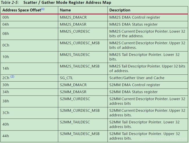
Scatter / Gather Mode Register Address Map
Scatter Gather Descriptor
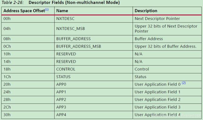
每个Descriptor有13个寄存器,但每个Descriptor地址需要以64字节对齐,也就是0x00, 0x40, 0x80; NXTDESC表示下一个描述符指针地址,BUFFER_ADDRESS为数据缓存的地址。Control储存Frame的开始、结束、每个Package的长度信息(以字节为单位),Status存储错误、结束等信息,APP0~APP4为用户使用空间(仅在打开Status Control Stream时有效)。
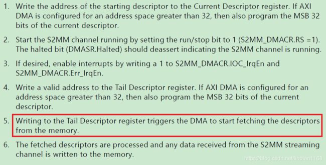
A DMA operation for the MM2S channel

A DMA operation for the S2MM channel
Zynq工程建立
20190818
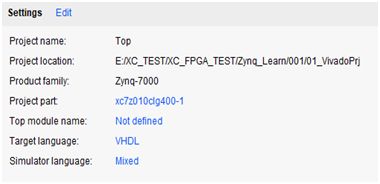
器件信息
器件型号 Zynq-7000 clg400,速率等级-1,xc7z010clg-1
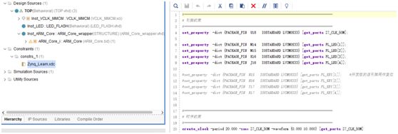
器件的PL部分XDC约束

建立PS核

DDR3配置
DDR3型号MT41J128M16 HA-125

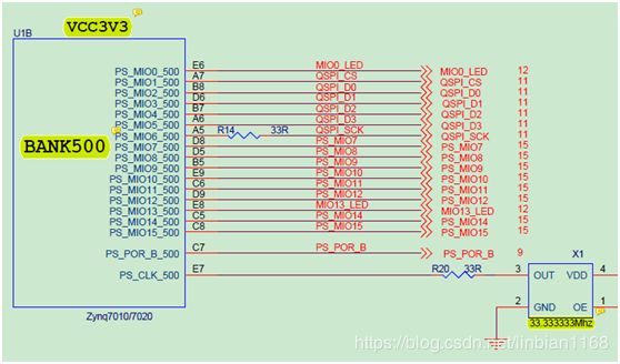
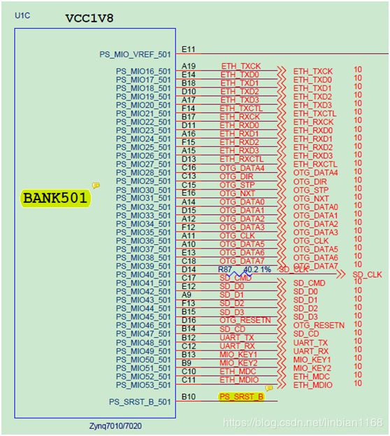
MIO配置
根据原理图的MIO连接关系对MIO进行配置,包括Bank0和Bank1的电压设置(3.3V、1.8V),UART、以太网等连接,
PL开发
PL的开发和通常的FPGA开发流程一致,可以在PL中例化ARM_Core,
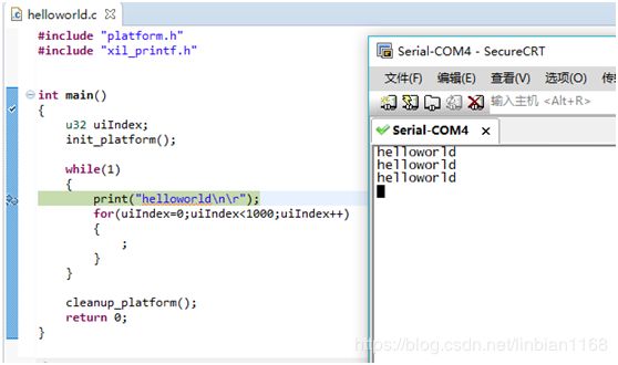
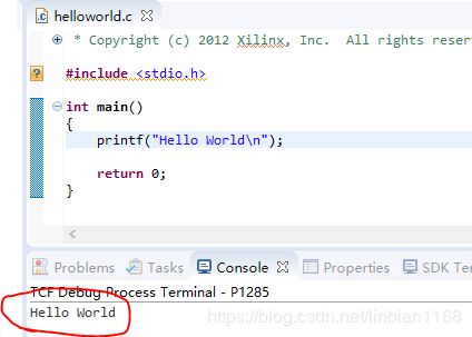
串口测试
20190819
串口测试时使用SecureCRT软件进行串口显示
Zynq固化
20190820
使用vivado烧写(不是在SDK中烧写) BOOT.BIN文件和FSBL.elf文件(不是黑金提供的下载qspi专用FSBL,是SDK工程中生成的)
测试工程

参考博文链接
Zynq系列FPGA如何固化bit文件到QSPI_Flash
MYIR-ZYNQ7000系列-zturn教程(9):将bit文件固化到QSPI_Flash
03-ZYNQ学习(启动篇)之程序的固化
使用FreeRTOS
FreeRTOS使用GPIO中断
20191208
使用含FreeRTOS的BSP,代码中不加入FreeRTOS的API函数,裸机运行,GPIO中断正常运行;代码中加入FreeRTOS的API函数,创建了两个task,在软件初始化的时候,进行GPIO中断的初始化(如下图注释掉的代码所示),结果发现GPIO的中断处理子程序一直进不去,
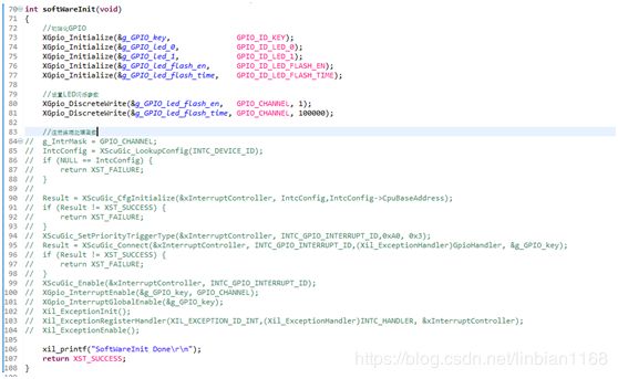
网上查了一下,原因应该如下图所示,

遂修改代码,

程序运行依然不正常;后重新下了一次bit,再次运行程序,依然不正常;猛的想到ZYNQ的ARM核是硬核,断了一次电,重下BIT,重跑程序,正常。
将FreeRTOS源码包含到工程中
20191231
在建立Application时直接选择使用FreeRTOS作为OS平台,可以直接将FreeRTOS源码包含到BSP中,并通过GUI对FreeRTOS进行配置。不过,若是在在不需更改配置的情况下,为便于其他人、其他工程直接复用考虑,似乎还是直接将FreeRTOS源码包含到工程中,较为便易。
将Vivado_SDK安装路径下的freeertos_bsp中的代码拷出,
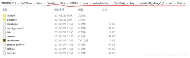
加入到工程源码中,

注意到,src右上角有一个小钥匙的标志,这是因为设置了include包含路径

凡是设置过文件属性的,都会出现这个标志,重启是不行的,即是将其删除,如果再新建一个,只要与原来的重名,这个钥匙标志还会有的,除非设置恢复为默认值。
编译、下载程序,正常运行

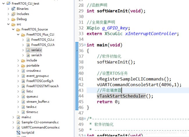
使用FreeRTOS_CLI
20200105
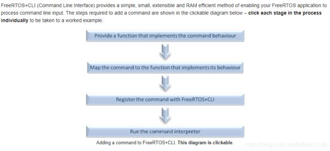
将CLI源文件加入工程中,并将下述路径的文件添加到工程中,
| 文件 | 描述 | 路径 |
|---|---|---|
| serial.h | 采用中断实现的串口驱动 | FreeRTOS\Demo\CORTEX_A9_Zynq_ZC702\RTOSDemo\src\Full_Demo |
| serial.c | 采用中断实现的串口驱动 | FreeRTOS\Demo\Common\include |
| Sample-CLI-commands.c | 该文件中定义了3个简单的命令及其处理函数 | FreeRTOS-Plus\Demo\Common\FreeRTOS_Plus_CLI_Demos |
| UARTCommandConsole.c | 该文件中定义了一个串口终端任务,在任务中获取串口字符,进行流水式处理,当解析到换行符时,调用FreeRTOS_CLIProcessCommand函数,在函数中处理对应的命令 | FreeRTOS-Plus\Demo\Common\FreeRTOS_Plus_CLI_Demos |
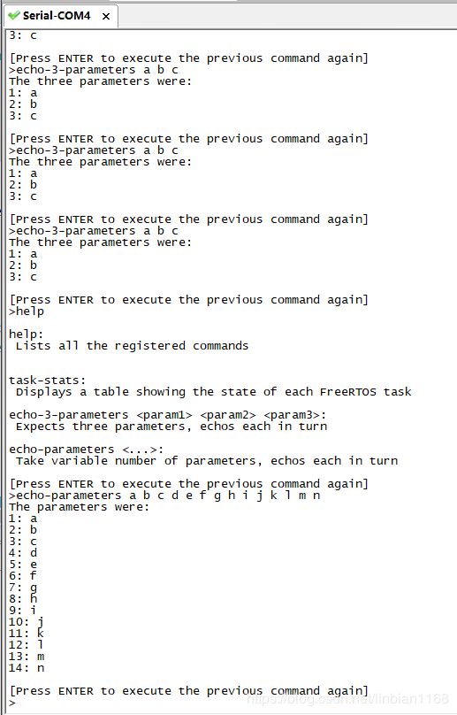
运行效果
解析串口数据包
20200106
基于UARTCommandConsole.c和serial.c修改,利用串口中断获得输入的串口数据,连续流式处理,解析出包头、数据包长度、数据包、包尾等。列出的函数分别完成串口初始化、串口中断注册和串口数据报文处理功能。
xComPortHandle xSerialPortInitMinimal( uint32_t ulWantedBaud, UBaseType_t uxQueueLength )
{
BaseType_t xStatus;
XUartPs_Config *pxConfig;

	xRxQueue = xQueueCreate( uxQueueLength, sizeof( char ) );
	configASSERT( xRxQueue );

	xTxCompleteSemaphore = xSemaphoreCreateBinary();
	configASSERT( xTxCompleteSemaphore );
	xSemaphoreTake( xTxCompleteSemaphore, 0 );

	/* Look up the UART configuration then initialise the dirver. */
	pxConfig = XUartPs_LookupConfig( XPAR_XUARTPS_0_DEVICE_ID );
	/* Initialise the driver. */
	xStatus = XUartPs_CfgInitialize( &xUARTInstance, pxConfig, XPAR_PS7_UART_1_BASEADDR );
	configASSERT( xStatus == XST_SUCCESS );
	( void ) xStatus; /* Remove compiler warning if configASSERT() is not defined. */
	/* Misc. parameter configuration. */
	XUartPs_SetBaudRate( &xUARTInstance, ulWantedBaud );
	XUartPs_SetOperMode( &xUARTInstance, XUARTPS_OPER_MODE_NORMAL );

	/* Install the interrupt service routine that is defined within this file. */
	xStatus = XScuGic_Connect( &xInterruptController, XPAR_XUARTPS_1_INTR,  (Xil_ExceptionHandler) prvUART_Handler, (void *) &xUARTInstance );
	configASSERT( xStatus == XST_SUCCESS );
	( void ) xStatus; /* Remove compiler warning if configASSERT() is not defined. */
	/* Ensure interrupts start clear. */
	XUartPs_WriteReg( XPAR_PS7_UART_1_BASEADDR, XUARTPS_ISR_OFFSET, XUARTPS_IXR_MASK );
	/* Enable the UART interrupt within the GIC. */
	XScuGic_Enable( &xInterruptController, XPAR_XUARTPS_1_INTR );
	/* Enable the interrupts of interest in the UART. */
	XUartPs_SetInterruptMask( &xUARTInstance, XUARTPS_IXR_RXFULL | XUARTPS_IXR_RXOVR | XUARTPS_IXR_TOUT | XUARTPS_IXR_TXEMPTY );
	/* Set the receive timeout. */
	XUartPs_SetRecvTimeout( &xUARTInstance, 8 );
	return ( xComPortHandle ) 0;
}
/* Standard includes. */
#include "string.h"
#include "stdio.h"
#include "FreeRTOS.h"
#include "task.h"
#include "semphr.h"
#include "xbasic_types.h"
#include "serial.h"

#define cmdMAX_INPUT_SIZE		50
#define cmdQUEUE_LENGTH			25
#define cmdMAX_MUTEX_WAIT		pdMS_TO_TICKS( 300 )

typedef enum
{
	eFindPkgHead = 0,
	eGetPkgLen,
	eGetPkgData,
	eFindPkgEnd
} eUartPkgState;

/*-----------------------------------------------------------*/
static void prvUartTask( void *pvParameters );
extern void vUartTaskStart( uint16_t usStackSize, UBaseType_t uxPriority );

/*-----------------------------------------------------------*/
/* Used to guard access to the UART in case messages are sent to the UART from more than one task. */
static SemaphoreHandle_t xTxMutex = NULL;

/* The handle to the UART port, which is not used by all ports. */
static xComPortHandle xPort = 0;

/*-----------------------------------------------------------*/
void vUartTaskStart( uint16_t usStackSize, UBaseType_t uxPriority )
{
	/* Create the semaphore used to access the UART Tx. */
	xTxMutex = xSemaphoreCreateMutex();
	configASSERT( xTxMutex );

	/* Create that task that handles the console itself. */
	xTaskCreate( 	prvUartTask,	/* The task that implements the command console. */
					"CLI",						/* Text name assigned to the task.  This is just to assist debugging.  The kernel does not use this name itself. */
					usStackSize,				/* The size of the stack allocated to the task. */
					NULL,						/* The parameter is not used, so NULL is passed. */
					uxPriority,					/* The priority allocated to the task. */
					NULL );						/* A handle is not required, so just pass NULL. */
}
/*-----------------------------------------------------------*/
static void prvUartTask( void *pvParameters )
{
signed char cRxedChar;
static eUartPkgState   ePkgState = eFindPkgHead;
static u8   ucPkgHeadAy[4] = {0,0,0,0};
static u8   ucPkgEndAy[4]  = {0,0,0,0};
static u8   ucPkgLength = 0;
static u8   ucCurIdx    = 0;
static u8   ucUartRecvBuffer[256];
BaseType_t xReturned;
xComPortHandle xPort;

	( void ) pvParameters;

	/* Initialise the UART. */
	xPort = xSerialPortInitMinimal( 115200, cmdQUEUE_LENGTH );

	for( ;; )
	{
		/* Wait for the next character.  The while loop is used in case
		INCLUDE_vTaskSuspend is not set to 1 - in which case portMAX_DELAY will
		be a genuine block time rather than an infinite block time. */
		while( xSerialGetChar( xPort, &cRxedChar, portMAX_DELAY ) != pdPASS )
		{
			;
		}

		/* Ensure exclusive access to the UART Tx. */
		if( xSemaphoreTake( xTxMutex, cmdMAX_MUTEX_WAIT ) == pdPASS )
		{
			//数据流式处理串口数据
			switch(ePkgState)
			{
				//查找包头
				case eFindPkgHead:
					if(ucCurIdx == 4)
					{
						ucCurIdx = 0;
					}
					ucPkgHeadAy[ucCurIdx] = (u8) cRxedChar;
					if((ucPkgHeadAy[0] == 0x55) && (ucPkgHeadAy[1] == 0x55) && (ucPkgHeadAy[2] == 0x55) && (ucPkgHeadAy[3] == 0x55))
					{
						ePkgState = eGetPkgLen;
						ucCurIdx  = 0;
					}
					else
					{
						ePkgState = eFindPkgHead;
						ucCurIdx++;
					}
					break;
				//获取包长度
				case eGetPkgLen:
					ucPkgLength = (u8) cRxedChar;
					ePkgState   = eGetPkgData;
					//清空
					ucPkgHeadAy[0] = 0;
					ucPkgHeadAy[1] = 0;
					ucPkgHeadAy[2] = 0;
					ucPkgHeadAy[3] = 0;
					break;
				//获取数据区
				case eGetPkgData:
					ucUartRecvBuffer[ucCurIdx] = (u8) cRxedChar;
					if(ucCurIdx == ucPkgLength-1)
					{
						ePkgState = eFindPkgEnd;
						ucCurIdx  = 0;
					}
					else
					{
						ePkgState = eGetPkgData;
						ucCurIdx++;
					}
					break;
				//获取包尾,正确则处理数据包,否则丢弃
				case eFindPkgEnd:
					ucPkgEndAy[ucCurIdx] = (u8) cRxedChar;
					ucCurIdx++;
					if(ucCurIdx == 4)
					{
						if((ucPkgEndAy[0] == 0xAA) && (ucPkgEndAy[1] == 0xAA) && (ucPkgEndAy[2] == 0xAA) && (ucPkgEndAy[3] == 0xAA))
						{
							pkgDataProcess(ucUartRecvBuffer,ucPkgLength);
							ucCurIdx      = 0;
							ucPkgEndAy[0] = 0;
							ucPkgEndAy[1] = 0;
							ucPkgEndAy[2] = 0;
							ucPkgEndAy[3] = 0;
						}
						ePkgState = eFindPkgHead;
					}
					break;
				default:
					break;
			}
			/* Must ensure to give the mutex back. */
			xSemaphoreGive( xTxMutex );
		}
	}
}
//-----------------------------------------------
//包处理函数
//-----------------------------------------------
void pkgDataProcess(u8 const *pucPkgData,u8 const ucPkgLen)
{
	u8 ucIndex = 0;
	for(ucIndex=0;ucIndex<ucPkgLen;ucIndex++)
	{
		xil_printf("%d\r\n",pucPkgData[ucIndex]);
	}
	return;
}
参考博文链接
zynq中断入门
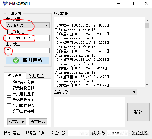
使用FreeRTOS_PLUS_TCP
20200112
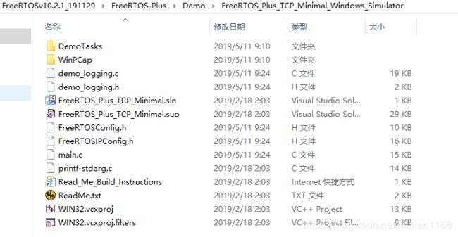
Xilinx SDK中提供了LwIP的代码范例,试着运行了一下,正常运行。不过,看到LwIP那繁多的代码,有些头大。而FreeRTOS官网提供了自己的TCP协议栈,代码文件并不多,比较适合来学习。FreeRTOS_PLUS_TCP网上的应用示例并不多,试着根据官方Demo在Zynq上运行一下,采用下图路径中的部分代码,主要是采用TCPEchoClient_SingleTasks文件,参考main文件,
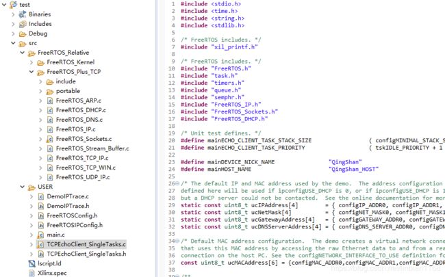
移植后如下图,
代码直接加入到工程中,直接编译是会报错的,需要自己在main.c中实现部分hook函数
void vApplicationIPNetworkEventHook( eIPCallbackEvent_t eNetworkEvent )
{
    static BaseType_t xTasksAlreadyCreated = pdFALSE;
    /* Both eNetworkUp and eNetworkDown events can be processed here. */
    if( eNetworkEvent == eNetworkUp )
    {
    	xil_printf("Network connection successful.\n\r");
        if(xTasksAlreadyCreated == pdFALSE)
        {
        	vStartTCPEchoClientTasks_SingleTasks( mainECHO_CLIENT_TASK_STACK_SIZE, mainECHO_CLIENT_TASK_PRIORITY );
            xTasksAlreadyCreated = pdTRUE;
        }
    }
}
/*-----------------------------------------------------------*/

/**
 * @brief User defined Idle task function.
 *
 * @note Do not make any blocking operations in this function.
 */
uint32_t ulApplicationGetNextSequenceNumber(uint32_t ulSourceAddress,
	uint16_t usSourcePort,
	uint32_t ulDestinationAddress,
	uint16_t usDestinationPort)
{
	(void)ulSourceAddress;
	(void)usSourcePort;
	(void)ulDestinationAddress;
	(void)usDestinationPort;
	return uxRand();
}

//---------------------------------------------------------
//需要用户实现的钩子函数
//---------------------------------------------------------
void vApplicationIdleHook( void )
{
    static TickType_t xLastPrint = 0;
    TickType_t xTimeNow;
    const TickType_t xPrintFrequency = pdMS_TO_TICKS( 5000 );
    xTimeNow = xTaskGetTickCount();
    if( ( xTimeNow - xLastPrint ) > xPrintFrequency )
    {
    	xil_printf( "." );
        xLastPrint = xTimeNow;
    }
}

const char * pcApplicationHostnameHook(void)
{
	return mainHOST_NAME;
}

BaseType_t xApplicationDNSQueryHook( const char *pcName )
{
		BaseType_t xReturn;
		/* Determine if a name lookup is for this node.  Two names are given
		to this node: that returned by pcApplicationHostnameHook() and that set
		by mainDEVICE_NICK_NAME. */
		if( strcmp( pcName, pcApplicationHostnameHook() ) == 0 )
		{
			xReturn = pdPASS;
		}
		else if( strcmp( pcName, mainDEVICE_NICK_NAME ) == 0 )
		{
			xReturn = pdPASS;
		}
		else
		{
			xReturn = pdFAIL;
		}
		return xReturn;
}

struct timezone;
struct timeval;
int _gettimeofday_r(struct _reent * x, struct timeval *y , struct timezone * ptimezone )
{
	( void ) x;
	( void ) y;
	( void ) ptimezone;

	return 0;
}

void vApplicationPingReplyHook( ePingReplyStatus_t eStatus, uint16_t usIdentifier )
{
	xil_printf("vApplicationPingReplyHook \n\r");
	switch( eStatus )
	{
		case eSuccess	:
			FreeRTOS_printf( ( pcSuccess ) );
			break;
		case eInvalidChecksum :
			FreeRTOS_printf( ( pcInvalidChecksum ) );
			break;
		case eInvalidData :
			FreeRTOS_printf( ( pcInvalidData ) );
			break;
		default :
			/* It is not possible to get here as all enums have their own
			case. */
			break;
	}

	FreeRTOS_debug_printf( ( "identifier %d\r\n", ( int ) usIdentifier ) );

	/* Prevent compiler warnings in case FreeRTOS_debug_printf() is not defined. */
	( void ) usIdentifier;
}
另外,还需要注意的是,FreeRTOS_ARP.C文件中需要添加xCheckLoopback函数,如下
BaseType_t xCheckLoopback( NetworkBufferDescriptor_t * const pxDescriptor, BaseType_t bReleaseAfterSend )
{
BaseType_t xResult = pdFALSE;
IPPacket_t *pxIPPacket = ( IPPacket_t * ) pxDescriptor->pucEthernetBuffer;

	/* This function will check if the target IP-address belongs to this device.
	 * If so, the packet will be passed to the IP-stack, who will answer it.
	 * The function is to be called within the function xNetworkInterfaceOutput().
	 */

	if( ( pxIPPacket->xEthernetHeader.usFrameType == ipIPv4_FRAME_TYPE ) &&
		( memcmp( pxIPPacket->xEthernetHeader.xDestinationAddress.ucBytes, ipLOCAL_MAC_ADDRESS, ipMAC_ADDRESS_LENGTH_BYTES ) == 0 ) )
	{
		xResult = pdTRUE;
		if( bReleaseAfterSend == pdFALSE )
		{
			/* Driver is not allowed to transfer the ownership
			of descriptor,  so make a copy of it */
			NetworkBufferDescriptor_t *pxNewDescriptor =
				pxDuplicateNetworkBufferWithDescriptor( pxDescriptor, ( BaseType_t )pxDescriptor->xDataLength );
			*( ( NetworkBufferDescriptor_t ** ) &pxDescriptor ) = pxNewDescriptor;
		}
		if( pxDescriptor )
		{
		IPStackEvent_t xRxEvent;

			xRxEvent.eEventType = eNetworkRxEvent;
			xRxEvent.pvData = ( void * ) pxDescriptor;
			if( xSendEventStructToIPTask( &xRxEvent, 0u ) != pdTRUE )
			{
				vReleaseNetworkBufferAndDescriptor( pxDescriptor );
				iptraceETHERNET_RX_EVENT_LOST();
				FreeRTOS_printf( ( "prvEMACRxPoll: Can not queue return packet!\n" ) );
			}

		}
	}
	return xResult;
}
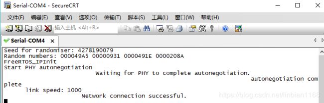
运行效果如下图所示
参考博文链接
STM32F4+FreeRTOS+FreeRTosTcpIp移植教程
SD卡读写
20200104
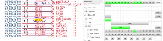
配置Zynq核的SD卡控制器,需要注意SD_CD信号(对应Card Detect)的设置,
使用FatFs_0.14
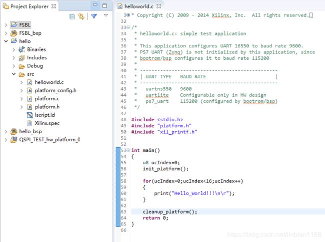
SD卡作为外部存储设备,可以作为载体存储文件。SDK中内置了对操作文件的库,如下
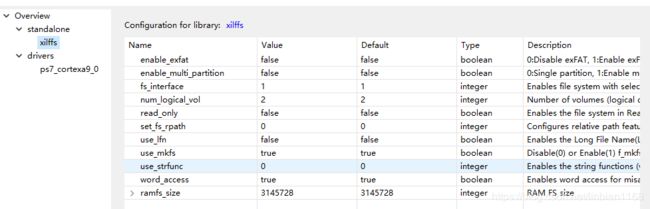
搜了一下,xilffs是FatFs在xilinx平台的移植版本,vivado_2018.3版本中的xilffs对应的是FatFs_0.13b版本,上网荡了一下,目前最新的FatFs是0.14版本。本着尝鲜的想法,从官网下了最新的FatFs,使用xxilffs中的diskio.h、diskio.c文件,

修改ffconf.h中的配置宏,修改FfsSdPolledExample函数中的f_mkfs部分,

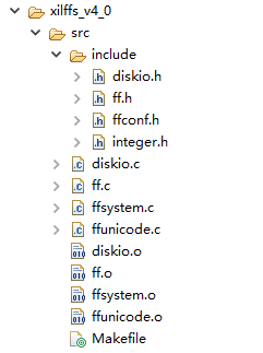
最终产生的文件为
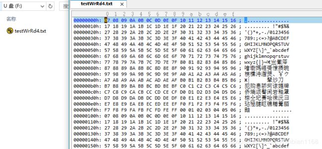
PS在线配置PL
20200105
在SD卡能正常读写之后,心里冒出一个想法,将配置文件放在SD卡上,zynq程序通过读取SD卡的配置文件到内存中,在线配置PL。空有想法,没有办法,一头雾水,忽而想到FSBL可以将bit和elf正常加载,那么FSBL中一定有方法。
方式1:借鉴FSBL


PcapLoadPartition函数位于pcap文件中,
/******************************************************************************/
/**
*
* This function loads PL partition using PCAP
*
* @param 	SourceDataPtr is a pointer to where the data is read from
* @param 	DestinationDataPtr is a pointer to where the data is written to
* @param 	SourceLength is the length of the data to be moved in words
* @param 	DestinationLength is the length of the data to be moved in words
* @param 	SecureTransfer indicated the encryption key location, 0 for
* 			non-encrypted
*
* @return
*		- XST_SUCCESS if the transfer is successful
*		- XST_FAILURE if the transfer fails
*
* @note		 None
*
****************************************************************************/
u32 PcapLoadPartition(u32 *SourceDataPtr, u32 *DestinationDataPtr,
		u32 SourceLength, u32 DestinationLength, u32 SecureTransfer)
{
	u32 Status;
	u32 IntrStsReg;
	u32 PcapTransferType = XDCFG_NON_SECURE_PCAP_WRITE;

	/*
	 * Check for secure transfer
	 */
	if (SecureTransfer) {
		PcapTransferType = XDCFG_SECURE_PCAP_WRITE;
	}

#ifdef FSBL_PERF
	XTime tXferCur = 0;
	FsblGetGlobalTime(&tXferCur);
#endif

	/*
	 * Clear the PCAP status registers
	 */
	Status = ClearPcapStatus();
	if (Status != XST_SUCCESS) {
		fsbl_printf(DEBUG_INFO,"PCAP_CLEAR_STATUS_FAIL \r\n");
		return XST_FAILURE;
	}

	/*
	 * For Bitstream case destination address will be 0xFFFFFFFF
	 */
	DestinationDataPtr = (u32*)XDCFG_DMA_INVALID_ADDRESS;

	/*
	 * New Bitstream download initialization sequence
	 */
	Status = FabricInit();
	if (Status != XST_SUCCESS) {
		return XST_FAILURE;
	}


#ifdef	XPAR_XWDTPS_0_BASEADDR
	/*
	 * Prevent WDT reset
	 */
	XWdtPs_RestartWdt(&Watchdog);
#endif

	/*
	 * PCAP single DMA transfer setup
	 */
	SourceDataPtr = (u32*)((u32)SourceDataPtr | PCAP_LAST_TRANSFER);
	DestinationDataPtr = (u32*)((u32)DestinationDataPtr | PCAP_LAST_TRANSFER);

	/*
	 * Transfer using Device Configuration
	 */
	Status = XDcfg_Transfer(DcfgInstPtr, (u8 *)SourceDataPtr,
					SourceLength,
					(u8 *)DestinationDataPtr,
					DestinationLength, PcapTransferType);
	if (Status != XST_SUCCESS) {
		fsbl_printf(DEBUG_INFO,"Status of XDcfg_Transfer = %lu \r \n",Status);
		return XST_FAILURE;
	}


	/*
	 * Dump the PCAP registers
	 */
	PcapDumpRegisters();


	/*
	 * Poll for the DMA done
	 */
	Status = XDcfgPollDone(XDCFG_IXR_DMA_DONE_MASK, MAX_COUNT);
	if (Status != XST_SUCCESS) {
		fsbl_printf(DEBUG_INFO,"PCAP_DMA_DONE_FAIL \r\n");
		return XST_FAILURE;
	}

	fsbl_printf(DEBUG_INFO,"DMA Done ! \n\r");

	/*
	 * Poll for FPGA Done
	 */
	Status = XDcfgPollDone(XDCFG_IXR_PCFG_DONE_MASK, MAX_COUNT);
	if (Status != XST_SUCCESS) {
		fsbl_printf(DEBUG_INFO,"PCAP_FPGA_DONE_FAIL\r\n");
		return XST_FAILURE;
	}

	fsbl_printf(DEBUG_INFO,"FPGA Done ! \n\r");

	/*
	 * Check for errors
	 */
	IntrStsReg = XDcfg_IntrGetStatus(DcfgInstPtr);
	if (IntrStsReg & FSBL_XDCFG_IXR_ERROR_FLAGS_MASK) {
		fsbl_printf(DEBUG_INFO,"Errors in PCAP \r\n");
		return XST_FAILURE;
	}

	/*
	 * For Performance measurement
	 */
#ifdef FSBL_PERF
	XTime tXferEnd = 0;
	fsbl_printf(DEBUG_GENERAL,"Time taken is ");
	FsblMeasurePerfTime(tXferCur,tXferEnd);
#endif

	return XST_SUCCESS;
}
为方便记,对SD卡文件的访问直接使用了xilinxt提供的xilffs,未采用最新的FatFs版本,
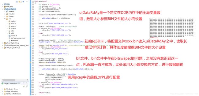
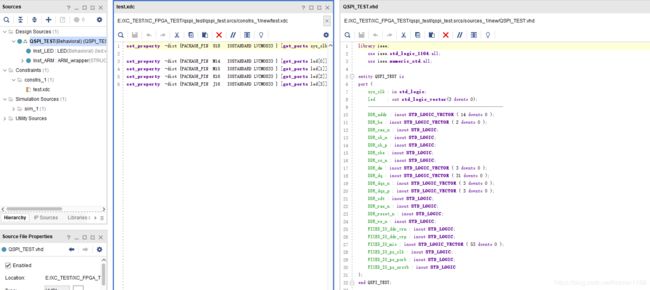
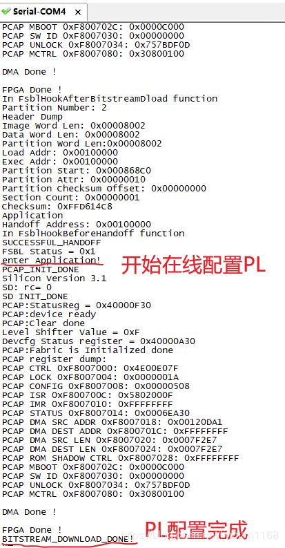
将FSBL.elf+testbit_1.bit+pl_config_test.elf生成BOOT.bin,选择配置模式为QSPI启动,烧到QSPI_FLASH中;当程序从QSPI中加载成功后,PL先是运行testbit_1,之后当在线配置PL成功后,PL运行testbit_2。开发板上有4个LED灯,testbit_2和testbit_1的区别是,testbit_1点亮LED_2号、LED_3,testbit_2点亮LED_1号、LED_4,可以直接通过观察LED的变化判断PL运行状态,也可以通过串口输出观测,
方式2:采用xdevcfg_polled_example
在没有发现需要对bin文件的数据 进行翻转之前,方式1一直走不通,不由得怀疑是走错了方向,网上荡了一圈,发现可以采用xdevcfg_polled_example来实现PS对PL的配置,
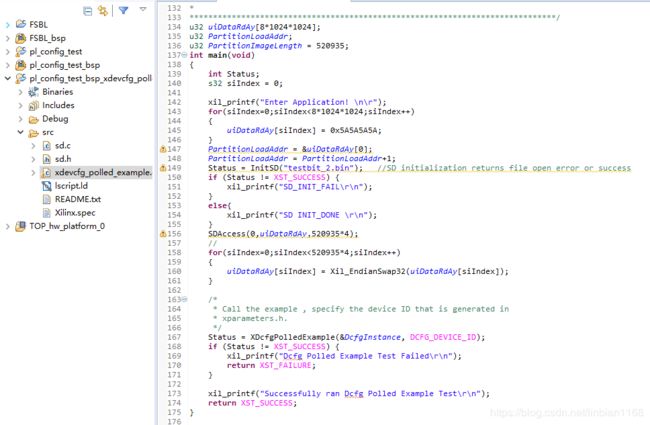
不过调用该example后,观测现象和方式1是一致的,这之后才怀疑是数据翻转的问题,更改之后,万事正常。
参考博文链接
Zynq动态更新FPGA比特流
Zynq SDK 驱动探求(五)软件动态重配置硬件比特流
AXI_DMA简单使用
20200313
使用Direct Register Mode
测试一
自回环模式,主要参照Using the AXI DMA in Vivado搭建硬件,软件直接使用Xilinx提供的范例,没遇到什么幺蛾子,顺利测试通过。

测试二
数据流向图如下,

搭建的Zynq原理图如下,
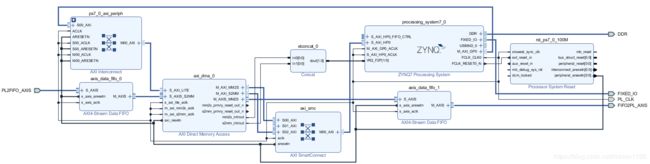
SDK程序中,封装了DMA操作、定时器操作。在主程序执行前发起一次DMA发送、一次DMA接收操作;在定时中断中查询DMA的完成状况,当发送完成后,再次开启发送流程;当接收完成后,再次开启接收流程;在DMA发送中断中,查询DMA是否正常发送,正常发送的话,则将发送完成标志置高,打印正常发送;在DMA接收中断中,查询DMA是否正常接收,正常接收的话,则将接收完成标志置高,打印正常接收。
在测试的时候,出现了问题,DMA数据正常发送几次后就不再发送了,一直没有输出DMA正常接收,但查看接收缓存区的内存,数据又正常搬移了。
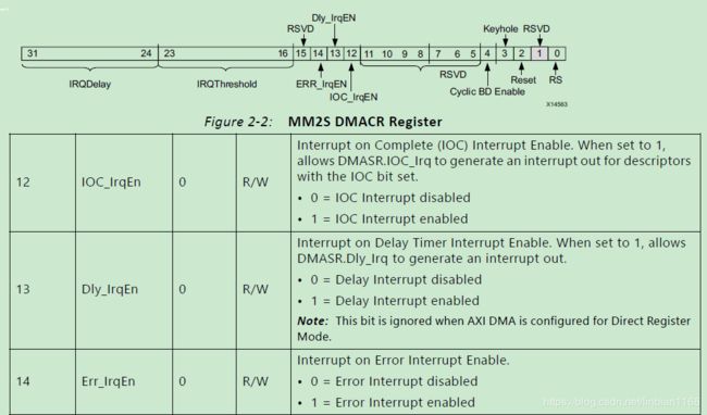
遂开始排查。在DMA的接收中断中,总是查询到S2MM_DMASR寄存器Err_Irq位被置位,从而DMA核被复位,DMA停止操作,这能解释为何DMA数据不再发送了。考虑到提示是中断错误,于是就排查是否中断设置不正常。查看手册,通过设置DMACR寄存器,可以将ERR_IrqEN禁能掉,

而原代码中有
XAxiDma_IntrEnable(&AxiDma_Instance, XAXIDMA_IRQ_ALL_MASK,XAXIDMA_DEVICE_TO_DMA);//使能所有中断
于是修改为
XAxiDma_IntrEnable(&AxiDma_Instance, XAXIDMA_IRQ_IOC_MASK ,XAXIDMA_DEVICE_TO_DMA);
然而没什么用。于是接着排查,看到代码中是这样设置中断的优先级和触发类型的,优先级为A0,类型为3(对应上升沿触发),
XScuGic_SetPriorityTriggerType(&g_Intc, RX_INTR_ID, 0xA0, 0x3);
而PL向PS的中断为高电平有效,于是修改为
XScuGic_SetPriorityTriggerType(&g_Intc, RX_INTR_ID, 0xA0, 0x1);
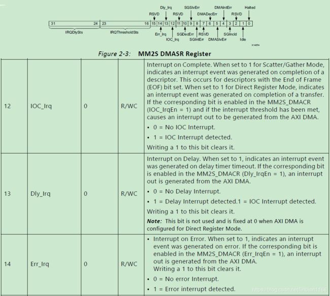
依旧没有什么用。在DMA接收中断函数里,直接读取整个S2MM_DMASR寄存器的值(原始值,不做MASK操作),发现Halted被置位,DMAIntErr被置位,Err_Irq被置位。

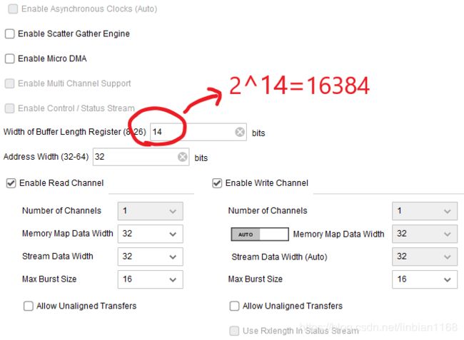
网上查询了一番,主要提及两种可能,一是DMA的缓冲区开的太小,二是DAM的接收端一直没有收到tlast信号。考虑到我设定的DMA单次传输大小为1024B,而设定的缓冲区为16384.因此排除可能一;遂排查FPGA代码,果然看到没有正确处理tlast信号。
一番修改之后,DMA接收中断中不再报错。
测试三
数据流向图如下,

搭建的Zynq原理图如下,
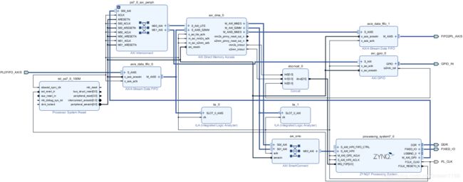
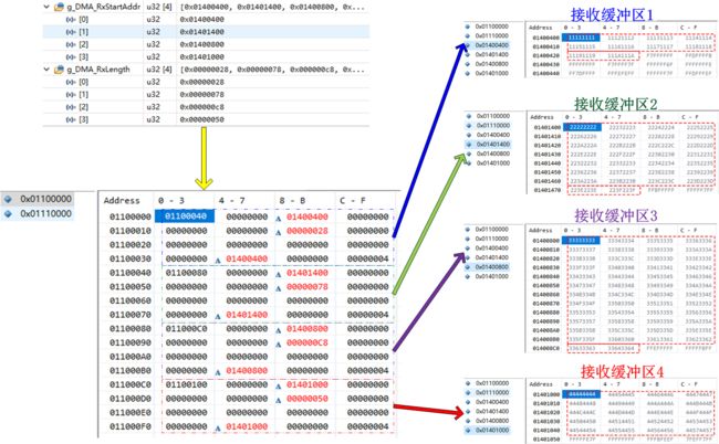
SDK程序中,封装了DMA操作、定时器操作、GPIO操作。在GPIO中断中,设定接收缓冲区的地址,发起DMA接收操作(有多个接收缓冲区地址可供选择);在DMA发送中断中,查询DMA是否正常发送,正常发送的话,则将发送完成标志置高,打印正常发送;在DMA接收中断中,查询DMA是否正常接收,正常接收的话,则将接收完成标志置高,打印正常接收。
刚开始测试时,多个接收缓冲区的数据能正常搬移,
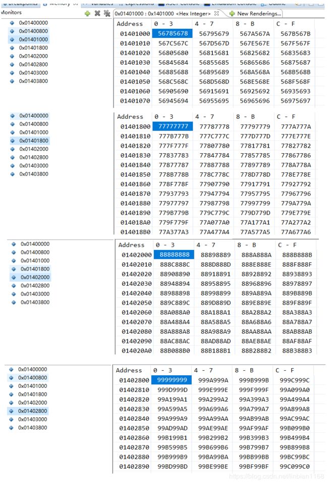
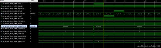
不过,当接收次数多了以后,会出现DDR3中数据没有正常搬移的情况,而观测到DMA的S2MM端口的地址和数据的确是正常操作的,
网上查了一下,没有什么收获,于是在每次准备更新接收缓冲区数据之前,先调用Xil_DCacheFlushRange函数,这样试了后,就正常了。
void Gpio_Handler(void *CallbackRef)
{
	int iDMARxStartIndex;
	int Status;
	XGpio *GpioPtr = (XGpio *)CallbackRef;

	iDMARxStartIndex = (g_uiGpioIntcNum%8);
	Xil_DCacheFlushRange((UINTPTR)g_DMA_RxStartAddr[iDMARxStartIndex], MAX_PKT_LEN);  //刷新DDR3
	Status = XAxiDma_SimpleTransfer(&AxiDma_Instance,(UINTPTR) g_DMA_RxStartAddr[iDMARxStartIndex],MAX_PKT_LEN, XAXIDMA_DEVICE_TO_DMA);
	if (Status != XST_SUCCESS) {
		return XST_FAILURE;
	}

	g_uiGpioIntcNum++;
	/* Clear the Interrupt */
	XGpio_InterruptClear(GpioPtr, GPIO_CHANNEL1);
}
参考博文链接
Problem-with-PL-generated-edge-sensitive-interrupts-in-Vivado
xilinx dma调试笔记
ZYNQ AXI DMA调试细节
ZYNQ AXI DMA调试细节(二)
ZYNQ AXIDMA详解(一)
使用Scatter/Gather Mode
20200314
测试一
自回环模式,搭建的Zynq原理图如下,

Xilinx提供的范例可以直接运行,会输出成功运行的字样。范例的流程大致如下所示,
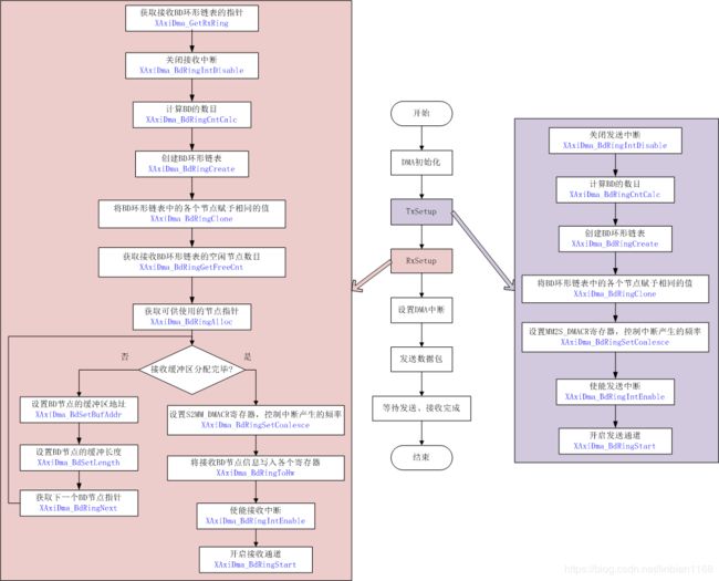
这里解释一下BD节点,BD节点构造成一个环形链表,

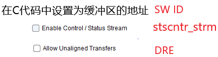
在C代码中,BD描述子的寄存器有三个,对应地址为0x34、0x38、0x3C,在手册中没有描述,
#define XAXIDMA_BD_ID_OFFSET		0x34  /**< Sw ID */
#define XAXIDMA_BD_HAS_STSCNTRL_OFFSET	0x38  /**< Whether has stscntrl strm */
#define XAXIDMA_BD_HAS_DRE_OFFSET	0x3C  /**< Whether has DRE */
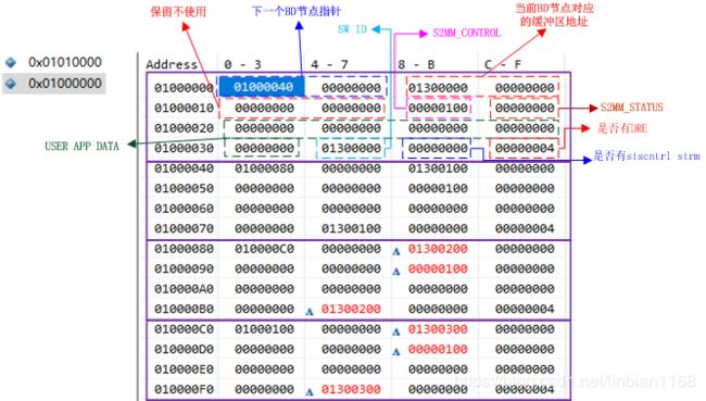
一个BD节点共计64个字节,定义如下,
#define XAXIDMA_BD_NUM_WORDS		16U  /**< Total number of words for one BD*/
typedef u32 XAxiDma_Bd[XAXIDMA_BD_NUM_WORDS];   //定义XAxiDma_Bd类型,为一个u32的数组
内存中的BD节点指针如下所示,各部分的含义如图中文字所示,
测试二
搭建的Zynq原理图如下,

SDK程序中,为简便记,一包数据由一个BD组成(当程序复杂时,可以由多个BD组成),存在一个缓冲区里。发送结果如下所示,


接收结果如下所示,
参考博文链接
Scatter-gather DMA 与 block DMA
一步步学习zynq软硬件协同开发(AX7021)【AXI-DMA】:AXI-DMA Scatter/Gather Mode(SG模式)
AXI DMA: How many packets per descriptor and what is a packet?
AXI DMA in SG mode
AXI DMA in SG mode : How to determine number of BDs and size of memory for BDs
PetaLinux
安装
20200316
安装版本为PetaLinux2018.3,主要参考以下链接,
petalinux2018.3安装教程,基于Ubuntu16.04.4
petalinux环境安装和基本编译
有两点要注意,
- 可以直接复制PC中的文件到虚拟机的文件夹中
- 在安装过程中,按enter查看协议内容,按q退出查看协议,按y接受协议内容
设计流程
20200318

vivado产生hdf
需要确保满足以下条件,
设置petalinux的环境
$ source <path-to-installed-Xilinx-Vivado>/settings64.sh
建立petalinux工程
$ petalinux-create --type project --template <PLATFORM> --name <PROJECT_NAME>
建立硬件配置
$ petalinux-config --get-hw-description=<path-to-directory-containing-hardware description-file>
编译工程
$ petalinux-build
这个过程会产生DTB(a device tree)、FSBL、U-Boot、Linux内核、根文件系统映像等,

生成uImage()
$ petalinux-package --image -c kernel --format uImage
生成BOOT文件
petalinux-package --boot --fsbl zynq_fsbl.elf --fpga --u-boot --force
初次使用
在编译过程中,出现过以下错误,
WARNING: petalinux-user-image-1.0-r0 do_rootfs: [log_check] petalinux-user-image: found 1 warning message in the logfile:
[log_check] warning: %post(sysvinit-inittab-2.88dsf-r10.plnx_zynq7) scriptlet failed, exit status 1
ERROR: petalinux-user-image-1.0-r0 do_rootfs: [log_check] petalinux-user-image: found 1 error message in the logfile:
[log_check] ERROR: ld.so: object ‘libpseudo.so’ from LD_PRELOAD cannot be preloaded (wrong ELF class: ELFCLASS64): ignored.
ERROR: petalinux-user-image-1.0-r0 do_rootfs: Function failed: do_rootfs
ERROR: Logfile of failure stored in: /home/langke/Desktop/ax_peta/build/tmp/work/plnx_zynq7-xilinx-linux-gnueabi/petalinux-user-image/1.0-r0/temp/log.do_rootfs.112226
NOTE: recipe petalinux-user-image-1.0-r0: task do_rootfs: Failed
ERROR: Task (/home/langke/Desktop/ax_peta/project-spec/meta-plnx-generated/recipes-core/images/petalinux-user-image.bb:do_rootfs) failed with exit code ‘1’
NOTE: Tasks Summary: Attempted 3044 tasks of which 2246 didn’t need to be rerun and 1 failed.
ERROR: Failed to build project
运行下述命令后,再重新编译,错误解决
sudo apt-get update
sudo apt-get install -y python tofrodos iproute2 gawk xvfb gcc git net-tools libncurses5-dev tftpd zlib1g-dev libssl-dev flex bison libselinux1 gnupg wget diffstat chrpath socat xterm autoconf libtool tar unzip texinfo zlib1g-dev gcc-multilib build-essential libsdl1.2-dev libglib2.0-dev
sudo apt-get install zlib1g:i386
sudo apt-get install screen
拷贝BOOT.BIN、image.ub两个文件到SD卡中,设置开发板为SD卡启动。使用 root 登录,默认密码 root。启动期间,部分串口输出如下,

参考博文链接
zynq学习笔记之petalinux (3)petalinux 创建自定义工程
petalinux(-)自动登录及启动配置
petalinux常用命令
petalinux初学者-使用教程-快速入门
Petalinux制作linux系统
petalinux 初上手
SDK调试Linux app
设置开发板的IP地址
ifconfig eth0 192.168.1.46 netmask 255.255.255.0
建立Linux TCF Agent

在线调试
其他
修改BSP设置后,源代码中的宏定义值使用异常
问题描述:在生成application的时候,选择了某个范例工程,之后修改了BSP中某个lib的选项设置,重新生成BSP,查看BSP中选型对应的宏定义已经改变,但是在工程代码中在调用选项的宏定义时,宏定义依然显示为修改之前的值。
解决措施:使用当前的BSP,重新生成一个application,将工程代码拷入即可。